Introduction
|
After 50 years of Philips Tuner development, we have reached the turn of the century, the year 2000. As described in Chapter 5, in the past decade the Philips Tuner business went through some fundamental changes. By 2000 the business was concentrated in two development centres, Krefeld (Germany) and Singapore, each with a volume production site in Kwidzyn (Poland) and Batam (Indonesia), respectively, while in Suzhou (China) production was ramping. More importantly, the last 10 years showed a major change in the product portfolio, moving away from TV tuners only. In several steps other RF applications were entered: satellite front ends and LNBs, multimedia frontends, communication modules and during the last years tuners for the new digital satellite and cable standards. In the classical TV tuner segment another dramatic change had happened, mainly due to the own initiative of the BU Tuners: the introduction of the WSP World Standard Pinning. This triggered a major change in the tuner market, one of the biggest being that the BU Tuners lost roughly 35% of its internal Philips TV volume. The more important second effect was a dramatic price erosion of the tuner function, being at only 3USD around the turn of the century. But, with the benefit of hindsight, we now know that these last ten years were quite calm compared to what would come next!
In this last chapter I will describe what happened in the turbulent last decade of the Philips TV, tuners and the associated semiconductor developments. Around the turn of the century the industry had reached the point where the centre of gravity of architectural ownership, cost and added value of consumer equipment shifted from the set (or module) maker to the semiconductor manufacturer. Although the semiconductor-driven integration was the engine of the continuous and spectacular price reduction of electronic equipment, it also changed traditional relations, focus areas of investment and management attention. But on the technology level major changes took place too, with unprecedented levels of integration and size reduction. These include the introduction of flat screen plasma and LCD TVs (plus the display technologies that did not make it), the change-over from analogue to digital TV, almost full integration of the TV processor, the Silicon Tuner, and all this in combination with price reductions to levels unheard of in the previous decades. New application segments were explored, like TV-on-Mobile, WiFi, GPS and even GSM, forcing the BL RF Solutions (as it became known throughout most of the period covered in this chapter) to adopt much more advanced packaging technologies. But then those applications allowed it to engage with leading players like Nokia, which in turn lead to the transfer to Philips Semiconductors, NXP and ultimately Nutune. And all this while volumes doubled to the unprecedented level of 50Mio modules by 2007, demanding enormous effort from the production organisation. In the background much bigger things determined developments at the level of the tuner business: where Philips had settled into a kind of stable mode with its Japanese competitors, now the Korean companies Samsung and LG came up aggressively, especially in the field of LCD TV. In parallel Philips tried to play in the emerging Silicon Valley biotope, until everybody was kicked out by the bursting internet bubble and dot-com crisis. And amidst all this Philips, Philips Consumer Electronics and Philips Semiconductors were struggling with the strategic questions how to cope with these challenges. Not surprisingly, it regularly resulted in major organizational changes, of which the tuner business was at best a part but often the victim. Ultimately it led to Philips selling off the business, be it TV, tuners, or semiconductors. Dramatic events ahead! |
Chapter navigation
|
Philips organization, 2000
Philips entered the year 2000 still under the unpopular Cor Boonstra, who, in the past 5 years as president of the company, hadn't visibly learned anything about electronics nor about inspiring leadership. And nobody understood yet what he meant with his "Let's make things better" company slogan. In the meantime, many businesses had been sold or closed, but the backbone of the company remained the vertical integration of (from top to bottom) Consumer Electronics, Semiconductors and Components. Lighting, Domestic Appliances, Medical Systems and Business Electronics remained as cash generating units. The company still entertained 1800 people in Corporate Research. During a presentation for the Research management in 2000 Boonstra boasted that in the previous 5 years he had closed 5 divisions and 40 business lines. With the money from these sales and a relentless cost cutting programme Boonstra achieved a sales peak of 37,9Bio€ and a profit of 9,6Bio€ in the year 2000. Boonstra also had the tendency to alienate the management members around him, e.g. Jan Tollenaar of Sound & Vision resigned angrily, while hiring strange short-lived managers like Roel Pieper as CTO and intended successor of Boonstra. He survived barely one year due to conflicts of interest and was replaced by Ad Huijser, former head of TV development and recently head of Corporate Research. In 1999 two acquisitions were made: the US company VLSI was purchased for 1BioUSD, while Philips obtained a controlling share in LG Displays for 1,5BioUSD. However, Boonstra was the champion of short-term capitalism in its worst form, and in 2001 and 2002 with the internet-bubble burst, sales collapsed by 15% to 32Bio€, while profits turned into a loss of 2,5Bio€. That cost him the last support of the Philips Board, and he was forced to resign towards the end of the year 2001, only to get involved in formal lawsuits for insider trading in and around the company of his mistress. He was acquitted due to a lack of formal evidence.
|
Boonstra was replaced by Gerard Kleisterlee, in contrast to the outsider that Boonstra always remained, a manager that had grown through the internal ranks of Philips Components, of which he had become the division head in 1999. Kleisterlee was definitely a different personality from Boonstra, much quieter, no bluff, no boasting, but also not a great inspirational communicator. He acted more as a book-keeper and was extremely risk-avoiding and allergic to unexpected developments, especially those related to the financial predictability. As a result, he obviously disliked the marginal profits of Consumer Electronics as well as the cyclicity of the Semiconductor business. The main strategy of Kleisterlee and his management therefore became maximum financial predictability and minimal share price variations. Consequently, the focus of the company started to shift from the vertically integrated consumer electronics to medical systems, which up to then had been one of the modest and unspectacular professional business segments within the company. The fact that it did not grow, had highly predictable income due to contracts with hospitals and solid margins, now made it the heart of the company in the eyes of Kleisterlee.
|
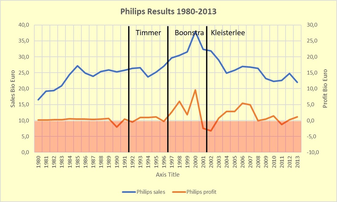
Sales and profit history of Philips. The precidencies of Timmer, Boonstra and Kleisterlee are indicated. After the inflated sales peak in 2000 the decline is obvious.
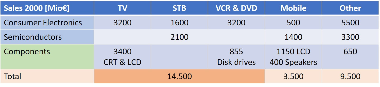
Rough split-up of the sales in the consumer pillar in the year 2000. Of the 38Bio€ company sales still 28Bio€ came from these businesses.
|

Philips president Gerard Kleisterlee. [Philips Annual Report 2004]

Philips CTO Ad Huijser.
|
The first victim of this new strategy was Kleisterlee's former PD Components. After he became the president of Philips, the Components division was taken over by Matt Medeiros, an American from Silicon Valley who, like most Americans at the time, believed the only place where one could develop new products was Silicon Valley. The headquarters of the Division were therefore moved from Eindhoven to Sunnyvale, and a major development site was created. At the same time Philips Semiconductors, for the same reason, was building up a massive organisation for developing CDMA-based 3G mobile phone ICs in nearby San José. The bulk of the Components business was still Display Components, by now a mix of CRT and - through the LG Joint Venture - LCD. Next to this, Components was market leader with black-and-white LCD displays for mobile phone applications, with Nokia as leading customer, while the new Liquid Crystal on Silicon (LCoS) technology was in development. Then, in 2001, the rapidly declining CRT Display business, with all its factories, was put into a joint venture with LG from Korea. This new entity named LG.Philips Displays was formally based in Hong Kong. This took the heart out of the division, which furthermore showed a 45% sales drop in 2001. This, in combination with the excessive costs of the Sunnyvale organisation, lead to the division Components being dissolved per January 1st, 2003. Matt Medeiros was fired, and the remaining activities spread across the other divisions. It also brought an end to the Silicon Valley presence of Philips, reducing it to a skeleton Semiconductor activity. As we will see, these developments also had major effects on the Tuner organisation!
|
|
Another development that was taking place within Philips, and especially Consumer Electronics, was the harmonization of the PCB manufacturing processes. This started around 1995 with project Lightning Stroke, a heavy top-down program that forced all units within Consumer Electronics to converge their PCB design of a limited set of 5 types, defining PCB material, thickness, metallization, number of layers, wired vs. SMD components, solder design rules, etcetera. The target was to harmonize all PCB stuffing and soldering processes, to create bigger factories that could serve multiple businesses with minimal process variation. This covered major factories of BGTV (Brugge, Dreux, Kwidzyn, Singapore, Manaus, Pune) but also VCR/DVD (Szekesfehervar, Hungary) and Audio PCB factories, in total nine. Around 1999 all these industrial activities were taken out of Consumer Electronics and concentrated in a new Philips Contract Manufacturing Services (PCMS). A last step was that, in 2002, PCMS was sold for 231Mio$ to the US EMS company Jabil. Only the final set assembly was now left within Philips.
|

October 2004 the Philips Board of Management unveiled the new company slogan "Sense and Simplicity", replacing the horrible "Let's make things better". It was on a big floating box in the Amsterdam canals.
|
Philips Tuners and RF Solutions organization, 2000-2006
It can not be denied that at the turn of the century the BU Tuners was in a bad shape. As shown in the previous chapter, after an initial surge in sales to 240MioUSD in 1995, under the pressure of WSP price erosion this number had declined to a 10-year low of 125MioUSD by 1999. BU manager Rob de Ridder was promoted away to BGTV Operations, and after an interim period, was succeeded by Noud de Loos, the former manager of the Thick Film business in Krefeld. He had the difficult task to turn around the business in a very uncertain time. A good thing was that he installed three business segments with a certain degree of freedom to operate in their domain: Tuners, Multimedia and Set Top Boxes. This immediately gave more balance and focus. Already in 1999, triggered by the bad results, discussions started at company level what to do with the Tuner business. With de Ridder gone, the BGTV probably thought they has squeezed the maximum profit out of the BU Tuners, and it was no longer interested to keep the tuner business. There were serious thoughts to sell the entire BU Tuners. On the request of Ad Huijser, my former functional boss in BGTV and then head of Philips Research, I was asked to explain the importance of the RF competence and the opportunities of RF applications to the head of PD Components Gerard Kleisterlee and his CTO Marino Carasso. This was just before Christmas 1999, and on June 29 the next year it was announced that the BU Tuners would move to the PD Components. I hope my explanations have helped to come to this decision (although they never tell you). The same happened in parallel to the Remote Control Business. Both Tuners and Remote Control, now Business Lines, ended up in the BU Advanced Ceramics and Modules (ACM), which had as main business the ceramic Surface Mounted Components (SMD resistors and capacitors) in Roermond, the Netherlands. This BU had ambitions for increased RF activities using their ceramic substrate technologies. However, before the Tuners had landed within ACM it was announced that the SMD business was sold per July 1st, leaving behind a much smaller BU ACM.
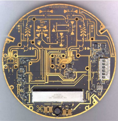
A typical Philips MMRadiolink microwave product: a 27-28GHz microwave radio link transceiver.
|
As already explained, the PD Components was not a stable nor quiet location, with overall a dramatic collapse of sales due to the bursting internet bubble in combination with the rapid decline of CRT displays. A continuous portfolio analysis was taking place, where the first victims were the two microwave activities: Hazel Grove (Manchester, UK) and Krefeld. In 1999 the first, Philips Broadband Networks, was moved into Corporate Redesign, the organizational basket containing all business going through a complete redesign or being prepared for sale. With this group the BU Tuners LNB group in Krefeld had jointly developed the 28 and 42GHz MVDS modules. Initially it was thought this activity had a bright future, and a heavy investment had brought it from 30 to more than 100 people. It was re-baptized into MM-Radiolink in the process. However, towards 2001 it was concluded that the future was not as bright as hoped for, sales was only 4Mio€ and the unit was made ready for sale.
|
The same happened to the Krefeld LNB business, which was larger at 12Mio€ sales, but this was 50% below budget because also the LNB market saw an enormous crunch. On June 1st, 2001 it was announced that both MMRadiolink and the LNB business were for sale. The LNB business was eventually sold to Newtech (Belgium) in March 2002, but the MMRadiolink organisation was closed. Newtech could use the Philips brand name for another two years, but quickly changed to the brand Skyware. Ironically, by that time the LNB production, which had used sub-contractors for everything but the PCB stuffing P1, was concentrated completely in Krefeld. It used fully automated production lines with only two operators, one at each end. All other manufacturing of the the BU Tuners had moved out of Krefeld to Kwidzyn (Poland) or Asia. So with this move, Philips lost its very last manufacturing operation in the once enormous Krefeld TV/VCR/Tuner factory.
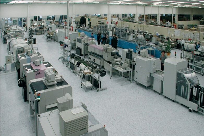
The fully automated LNB production line in Krefeld. The pink covers belong to the FCM component placement machines, behind them the reflow ovens. [Leaflet Skyware LNBs, 2002]
|
The same production line from the other side. note that only half of the hall is used. [idem]
|
As explained in the previous section, in the meantime the PD Components headquarters had moved to Sunnyvale, the focus was on supposedly rapidly growing emerging segments around wireless connectivity, and loss-making units in older segments were analysed for their strategic future. Including Tuners, because 2001 was a bad year with 8% negative Income from Operations (IFO). Tuners was now part of the renamed BU Emerging Electronic Systems (EES) which also contained Remote Control, Speaker Systems and Wireless Connectivity. The strategy department of Components started an analysis of the Tuners business and concluded it should be driven in a different direction. To start with, in November 2001 Noud de Loos was replaced by Pieter Paumen from the mentioned Strategy Department, and the BL received a new name to symbolise the fresh start: RF Solutions. But there was more, the BL was split into two separate business entities:
- BL Tuners, based in Singapore, would focus on the standard TV tuner (and the remaining TP900 VCR modules), and keep the Batam and Suzhou factories. Essentially this meant all liabilities were put into this BL: the rapidly declining tuner sales due to the WSP price erosion, and the Batam fab with its more than 1000 employees. The BL was assumed to remain profitable by doing contract manufacturing, first for the BL RF Solutions, but also for third parties. It was led by K T Goh, since 1996 the plant manager of Tuners Singapore. In total 169 non-production people (in Philiops terminology "indirects"), which included some 25 R&D personnel.
- Manufacturing activities in Singapore were stopped almost completely, all P2 (component stuffing) and P3 (alignment and test) moving to Batam and Suzhou. Only a prototype line remained and for a while the P1 (SMD placement) but also these would move to Batam soon.
- BL RF Solutions, based in Eindhoven, would take over development and sales - but not production - of all multimedia, satellite, and digital transmission modules. RF Solutions would buy manufacturing services from BL Tuners and thus became a fab-less business. It kept some 27 fte development staff in Krefeld and took over 18 R&D people in Singapore.
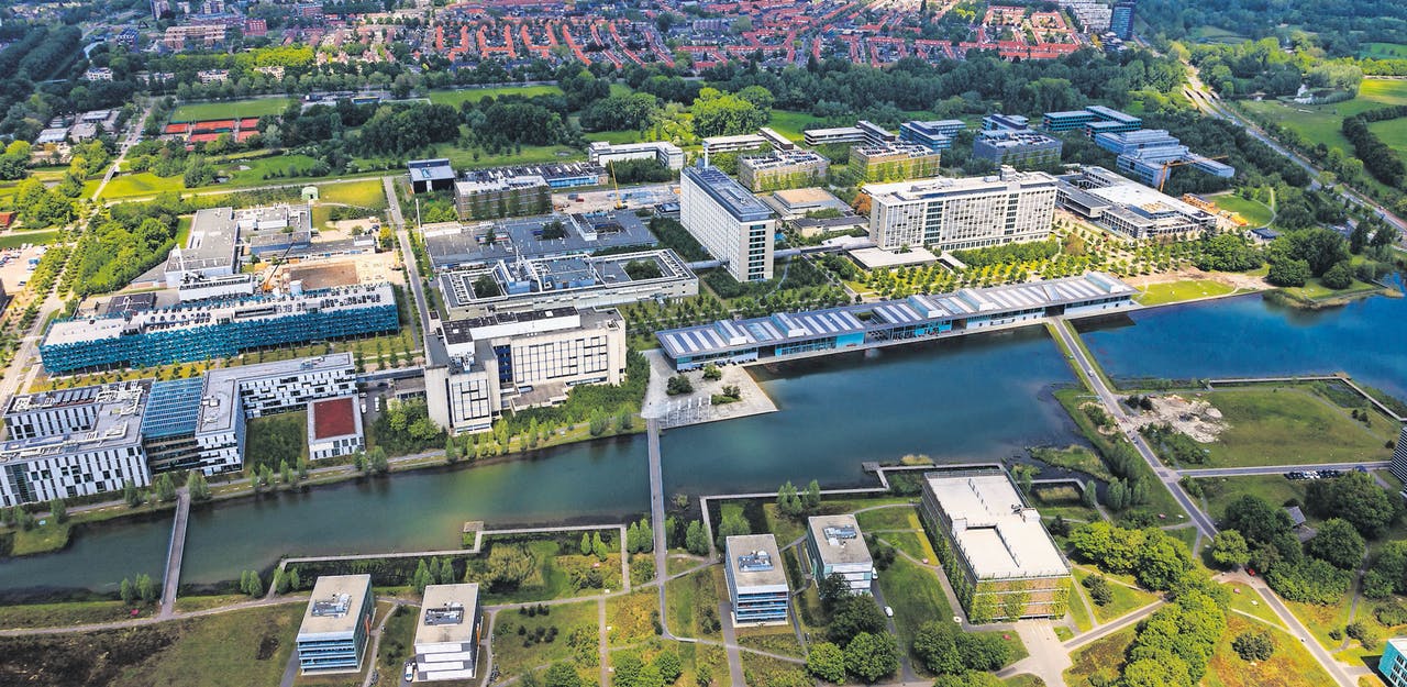
Driven by the vision of Rick Harwig, the new head of Research, from around 2000 the NatLab Research complex went through a massive transformation. On the one hand third party R&D activities were invited to the new complex, while in parallel all remaining Philips activities in Eindhoven were concentrated here. Many new buildings were erected, including large restaurant facilities along the pond, The Strip. It now houses around 12.000 employees.
|

In Singapore, Toa Payoh Philips still occupied its four former factories, although production quickly moved out. Tuners and RF Solutions remained in TP3, where a Medical Customer Training Centre occupied the former Tuners production floor.
|
But developments didn't end here. Having barely landed in the PD Components during 2002, both BLs were confronted with the dissolution of the PD by the end of the same year. The number of PDs interested in Tuner business was zero: Consumer Electronics had dumped them a year ago and Semiconductors was not interested in modules. Consequently, both BLs also ended up, together with quite a few other businesses, in Corporate Redesign, which had just sold off the LNB business. Having gone through the strategic analysis that lead to the split of RFS and Tuners, the obvious intention was to keep RF Solutions, which was deemed to be the promising growth part, and to get rid of Tuners with its manufacturing liabilities and diminishing margins. During 2003 several companies were approached for buying the BL Tuners, but eventually no deal was made. In fact, Corporate Redesign concluded that BL Tuners could not be sold stand-alone, but only in combination with something offering it a future: BL RF Solutions. And so, it was decided that per 1-1-2004 the two would merge again, becoming the new BL RF Solutions. With the clear intention to sell this business!
With all these strategic analyses and organizational changes, the portfolio split within the Tuner business became even more evident. On the one side were the good old TV tuners, and for a short while the dying TP900 tuner-modulators for VCR. Here price erosion continued in a devastating way, reducing the standard WSP tuner price from 3,4USD in 2000 to 1,99USD in 2005. Of course, this trend severely impacted the tuner supplier world, and especially the Japanese smaller players with their expensive cost base soon gave up: Hitachi, NEC, Sony and Sanyo. Although the Philips tuner volumes remained high throughout this period (around 17-18Mio pcs/year), the company was not able to grab additional volume due to this consolidation, mainly because new Chinese and Korean players stepped in with even lower prices. For Philips there was no way to compensate for this price erosion, so sales and margins declined continuously.
After the spin-off of the LNB business in 2002, there remained two dominant application clusters for RF Solutions: PC-Multimedia (PC-MM) and Set Top Box (STB). During the first years of the decade PC-MM, the FI/FM/FQ1200 family, was the cash generator of the BL, with a constant market share of 60-55%. This despite relatively very small investments, because for many years BU Strategy deemed it to be an unattractive market segment! Although the MM frontends were also used in the first small screen size LCD-TVs and monitors, the main issue was the lack of real market growth. TV on a PC remained a niche and was later replaced by video streaming.
The STB market was where the digital transition was taking place, first in Satellite, then Cable and ultimately Terrestrial reception. RF Solutions was an active player in all three of these segments, with all the positive and negative consequences: broad player, large experience, but many different products and impossible to focus. On top of that, typical for these type of system changes, the market and customers are uncertain and tend to watch competition before deciding, there are multiple scenarios that can be followed, with different (large) players following different scenarios, leading to different products for the same segment. In general, the BU followed the approach to have PC-MM products based on the 1200-family frames with Philips pinning, while STB products were all based on WSP, but this was only in theory, because especially the 1200-products were used in STB too.
In this chapter we will thus see many different product families:
- Analogue tuners UV1300-Mk4, UV1300-Mk5
- Analogue MM-frontends FM/FQ1200-Mk3, FQ1200-Mk4, FQ1200-Mk5
- Hybrid MM-frontends FCV1200, FMD1200-Mk3, FQD1200-Mk5, FQD1100
- Terrestrial NIM TU(V)1200
- Terrestrial digital tuners TD1500, TD(M)1300-Mk1, TD1300-Mk2, TD1300-Mk3, TD11/1600, TD1700, HD1800
- Cable frontend CDM1500, PM1300, CDX1200, CD(M)1300, CD1600
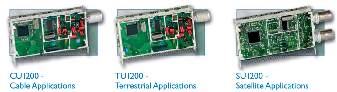
- Cable NIM CU1200, CU1200-Mk3
- Satellite frontend SD1200-Mk3, SDM1700, SD1800
- Satellite NIM SU1200, SU1200-Mk2
The NIMs mentioned in above list were the real new product concept of the BL: Network Interface Modules, the full RF, IF and digital channel decoding function in one module. In other words, RF-to-MPEG2 Transport Stream conversion. As introduced in the previous chapter the BU Tuners had experimented with these full conversion function in the QP1200 and QA900 products, but these were still using a tuner on a PCB. With the NIM it became all integrated on one PCB inside a single module.
DVB-T OFDM, Digital terrestrial TV, 1997
In the previous chapter the first two digital broadcast standard were introduced: DVB-Satellite and DVB-Cable. The introduction of these standards was determined by the complexity of the modulation and demodulation, which is dependent upon the channel characteristics. Reception of geostationary satellites provides the most stable radio channel: very stable wide channels, only minor received power variations due to cloud and rain attenuation, but a low power budget due to the long distance. QPSK has therefore been selected, requiring the lowest Carrier-to-Noise Ratio (CNR) and thus most robust against received power reductions. No channel adaptation or equalization is required. The cable transmission channel, in contrast, is much more variable, especially the frequency-dependent transfer characteristic, which varies substantially due to reflections within the cable network. In the time domain this is equivalent to echoes. However, the cable network easily offers high SNR, so to squeeze sufficient bit rate into a standard 8, 7 or 6MHz TV channel the higher order 64-QAM and 256-QAM modulation scheme is used, in combination with equalizers in the receiver.
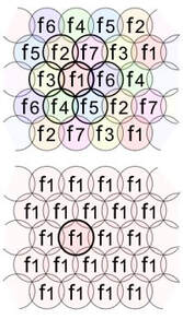
The spatial allocation of transmitter frequencies in traditional analogue TV broadcast (top) and a Single Frequency Network (bottom). [Wikipedia]
|
The ultimate target for Digital TV, however, was obviously digital terrestrial broadcast, given that some 70% of consumers watched terrestrial off-air broadcast. Of the three broadcast systems (off-air, cable and satellite) off-air clearly has the least well-defined radio channel: received signals can vary considerably in amplitude (the reason why tuner AGC has been such an important issue throughout this Tuner History), while multipath reception or frequency selective fading can lead to serious picture distortion. Similarly, reception of an unwanted signal at the same frequency also gives picture disturbance. In the world of analogue TV, the latter problem was solved through an internationally coordinated system of careful frequency planning and allocation, guaranteeing that transmitters with the same frequency were sufficiently far apart. One of the ambitions of the new DVB-Terrestrial (DVB-T) standard was thus to solve both the multipath as well as the frequency allocation problems. Ultimately DVB-T was designed to support Single Frequency Networks (SFN), all transmitting the same channel on the same frequency. Obviously, when a standard is performs well in an SFN it is also robust to echoes.
|
|
The technical solution to this challenge is Coded Orthogonal Frequency Division Multiplexing (COFDM, often shortened to OFDM). In QPSK and QAM the signal modulated on the RF carrier has the full symbol rate, thus occupying the full signal bandwidth and being sensitive to frequency selective fading, which in turn requires complex equalizers. In OFDM, in contrast, the incoming digital bitstream is split into many parallel symbol streams, each modulating a closely spaced frequency carrier. Using the proper relation between the individual carriers they become orthogonal, i.e. their frequency domain side lobes are zero at the centre frequencies of all adjacent carriers. In DVB-T either 1705 (2k) or 6817 (8k) carriers are used, which can be modulated individually using QPSK, 16-QAM or 64-QAM. Of course, a higher order modulation gives a higher bitrate and in practice 64-QAM is used. The distance between 2k-carriers is 4464Hz and for 8k 1116Hz, both fitting within an 8MHz channel (4464 * 1705 = 1116 * 6817 = 7,6MHz). Because all carriers are modulated equally the resulting frequency spectrum of an OFDM signal is almost perfectly flat, providing a very high bandwidth efficiency. To facilitate analysis of the effective frequency-dependent channel characteristic some 10% of the carriers is not used for data transmission but as fixed pilot, spaced evenly across the channel width and changing for every symbol. The strength of the pilots is used to estimate the Channel Transfer Function in the receiver, facilitating fast and adaptive equalization without complex computations.
For transmission the so constructed frequency domain signal is translated to a time domain signal using an Inverse Fast Fourier Transform (IFFT). When the carrier distance is 1116Hz for an 8k system as given above, the symbol length Ts is 1/1116= 896us. An important characteristic of OFDM is now the guard interval or cyclic prefix, where a fraction 1/m of the first part of the symbol is repeated and added at the end, thus lengthening the symbol. The parameter m can be 32, 16, 8 or 4, lengthening the symbol to 924, 956, 1008 or 1120us. At the receiver these lengthened symbols allow the reception of delayed multi-path signals, the longer the guard interval, the larger the possible delay: for 2k and 1/32 the max delay is 7us equivalent to 2,1km, for 8k 1/4 it is 224us or 67,2km. Obviously, the longer the cyclic prefix, the lower the effective data throughput. |
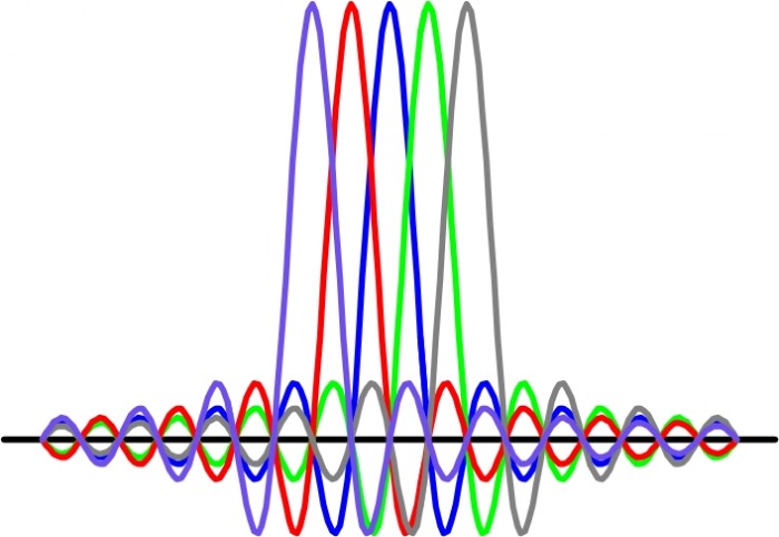
Example of 5 orthogonal OFDM BPSK-modulated carriers. At the centre of a carrier all other signals are zero. [DSP-related.com]
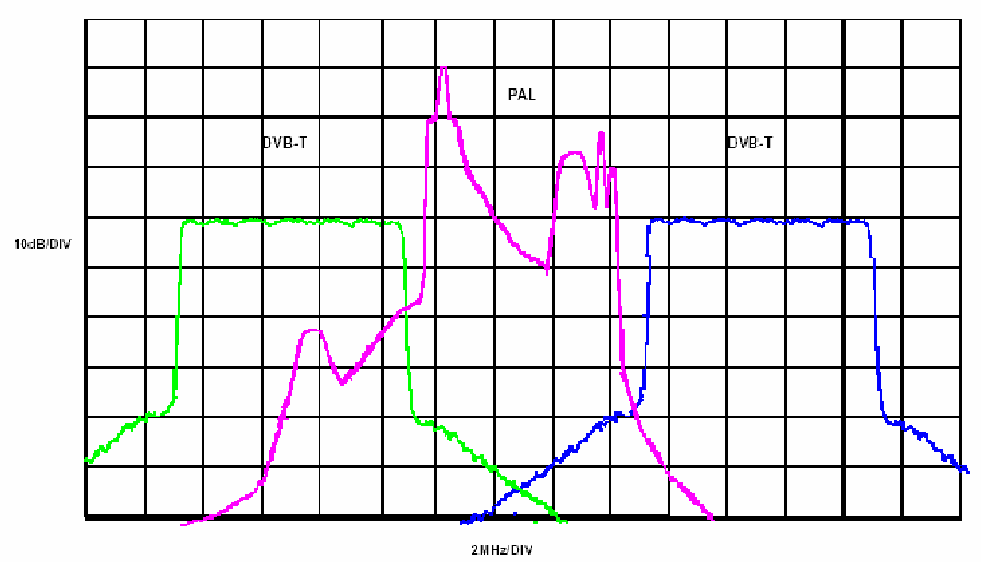
Spectral scan showing the clear differences in spectral density of a classical PAL TV signal (purple) and two adjacent OFDM signals. The situation shown (one PAL channel between two DVB-T channels) happens in practise and is the reason for stringent N+/-1 requirements. [SemanticScholar.org]
|
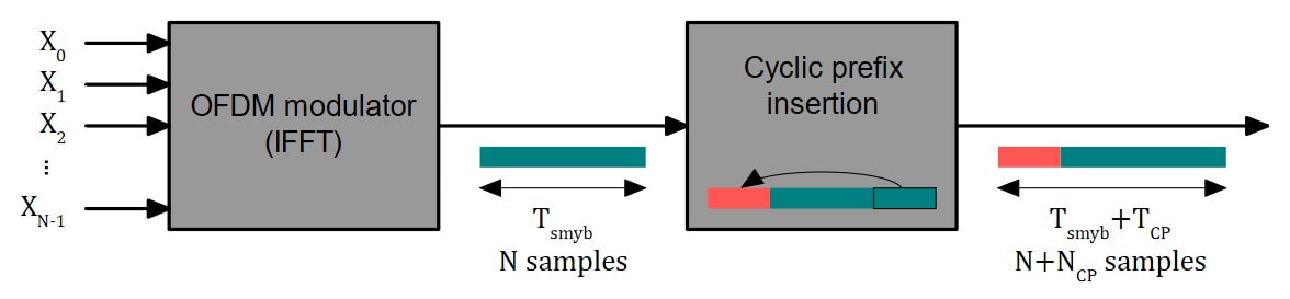
Concept of the cyclix prefix insertion in an OFDM transmitter. [Wikipedia]
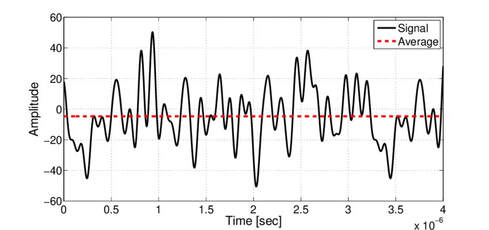
Typical OFDM time domain signal, showing the high PAPR. [Researchgate.net]
|
With these measures DVB-T is a system standard that is very robust against multi-path fading and/or variable frequency-dependent channel characteristics. The channel includes the receiver frontend part, and tuner tilt is thus no longer an issue for OFDM. In contrast, given the many carriers, LO frequency stability and phase noise are more critical, requiring large loop bandwidth PLLs. Furthermore, due to the statistically independent nature of the 2k or 8k orthogonal carriers they add non-coherently in the time domain, which means that the instantaneous signal amplitude can vary substantially. OFDM signals therefore have a high Peak-to-Average Power Ratio (PAPR) and need around 10dB back-off to avoid non-linear distortion.
And finally OFDM is very sensitive to (analogue) N+/-1 adjacent channel interference. For this there was no other solution than using two SAW filters in series, which in turn required additional IF amplifiers to compensate for the high SAW insertion losses. |
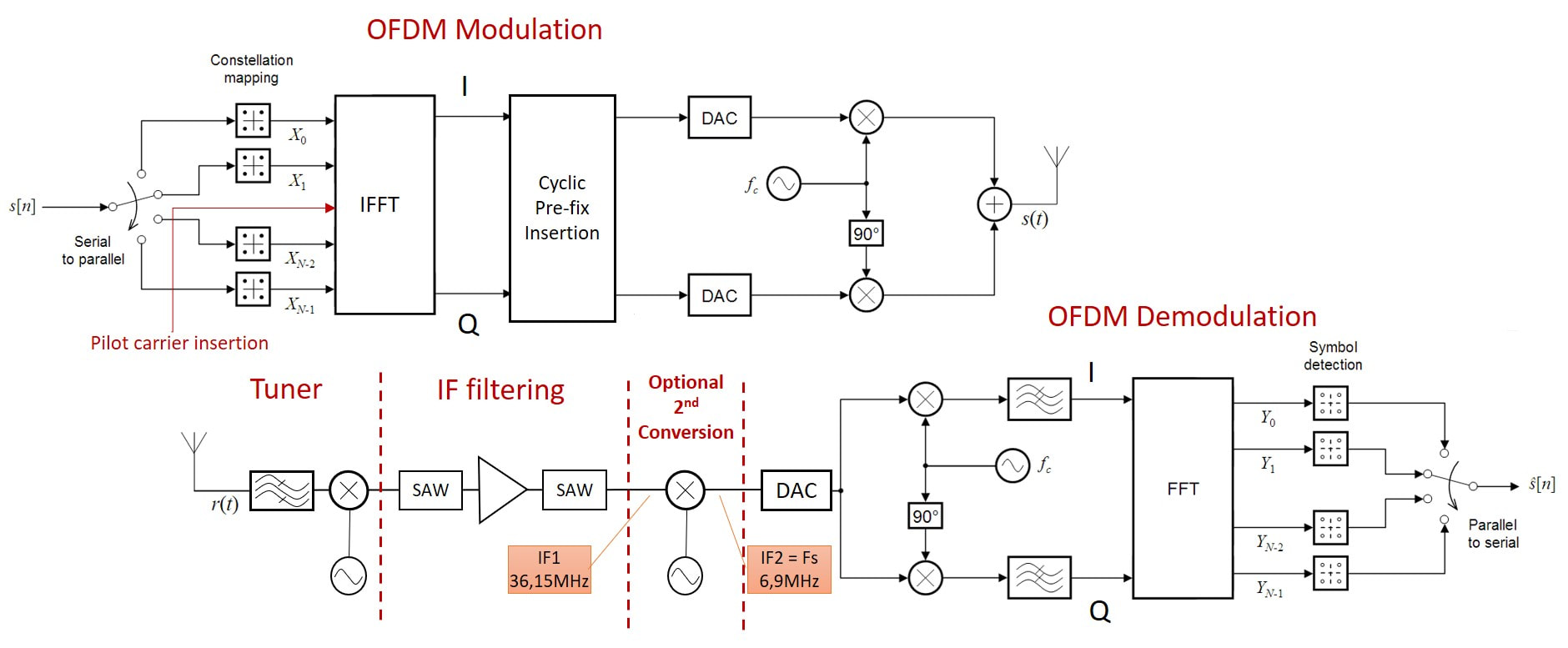
Typical architecture of an OFDM transmit-receive chain. The input and output are the coded MPEG2 streams. Because of the high adjacent channel rejection requirement most OFDM receivers required two SAW filters, with an additional amplifier to compensate for the losses. Early systems required a second down-conversion with IF2 equal to the symbol rate. [Modified from Wikipedia]
|
DVB-T is clearly a flexible standard, where operators can play with the system settings to optimize the quality and number of channels transmitted within one RF channel. For this they have the puncturing rate (1/2 to 7/8), the sub-carrier modulation format (QPSK, 16-QAM, 64-QAM) and the length of the cyclic prefix guard interval (1/4 to 1/32). Between the extreme settings this means the effective bitrate can be set between 5,0 and 31,7Mb/s, where the bitrate can be traded off against higher quality/resolution and higher multi-path robustness. To most operators the number of channels is most important, so typical bitrates are around 26Mb/s.
DVB-T was defined towards 1997, with first experimental transmissions from 1998 onwards in Singapore and the UK, and first formal introduction from 2001 onwards in the UK, Sweden, and Spain. Many countries followed. In the end all of Europe and 90% of Asia and Africa, except for Japan and China, converted to DVB-T over time. In Japan the Integrated Service Digital Broadcast - Terrestrial (ISDB-T) was adopted, also based on OFDM but now in 13 sub-channels, where single or combined channels can be QAM-modulated. In a slightly modified form this standard was also chosen by Brazil first and then the majority of South America. China developed its own DTV standard DTMB ten years later, allowing it to include more advanced signal processing features but still based on OFDM. It was introduced in 2006. Only the US ATSC system was different and will be discussed separately. |
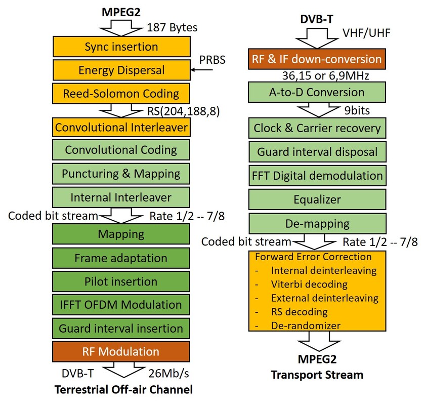
The full coding, modulation, demodulation and decoding chain of DVB-T. The encoding part up to the coded bit stream is almost identical to DVB-S.
|
Evidently all relevant Philips departments were involved with the early development and roll-out of DVB-T: Research in the standard setting, Digital Networks (Suresnes, Eindhoven) to develop the STBs, Philips Semiconductors for the ICs, and BU Tuners for the front ends.
TD1500 and TDM1300, the first OFDM tuners, 1998-2003
The roll-out of DVB-S first and then DVB-C as described in the previous chapter happened within 2 years of the respective standards releases. This was possible because in both cases the receiver function was a Set Top Box (STB), in most cases provided by the operator. When a standard changed from analogue to digital the service provider would simply exchange the customer STB. The connection from the STB was preferably a new digital interface (HDMI), otherwise analogue (SCART) or worst case re-modulated on a carrier. In none of these cases the consumer needed to change its TV, assuming it had at least one of the mentioned interfaces. The DVB-T receiver was different and much more difficult because it was intended to replace the classical analogue TV tuner function. From the start there were at least two system challenges when introducing DVB-T in TV sets:
- how to provide both the new digital as well as the old analogue TV reception, which were to co-exist for at least another decade?
- what was the optimal system (read module) partitioning for OFDM reception?
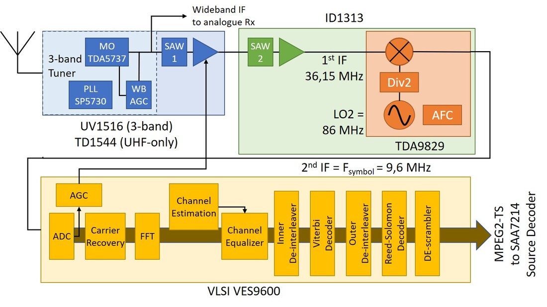
Block diagram of the digital channel section of the Philips IFA-1999 OFDM demo, which used the UHF-only TD1544. The ID1313 was an IF module containing the second SAW filter and amplifier. Although asked by some initial customers these modules were hardly ever actually sold.
|
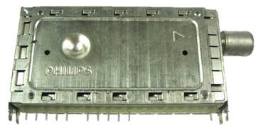
The UV1516/I with the unique sliding cover, here shown when closed. The large dent in the cover is for ground contacting.
|
|
The first tuner for the OFDM application used the new 1500 WSP frame, introduced with the CD1516 cable tuner earlier the same year. In contrast to the the cable product, the OFDM tuner used the same tuner core for the analogue and digital reception and did not require a splitter or loop-through function. The uncertain times around the emerging DVB-T reception are illustrated by the fact that the first 3-band tuner was still called UV1516, while the UHF-only 1-band version became the TD1544, using the new product code TD for Terrestrial Digital. Because of the important off-air reception the TD1500 family featured the discrete Wideband AGC from the UV1316-Mk2 and the internal 5V-to-33V DC/DC converter from the FI/FM1200-Mk2. Interestingly, the most dominant European type in this initial phase was the UHF-only TD1544, still using the 3B-MO but with de-populated VHF bands. There were two reasons for this: the BBC was a leading partner in developing the first OFDM tuner since they were aggressively pushing DVB-T deployment in the UK to counter the success of Rupert Murdoch's BSkyB DVB-S satellite broadcast. At the same time, most initial DVB-T deployment plans in Europe (Sweden, Germany) focussed on the UHF only; only later would DVB-T be extended to the VHF-III.
|
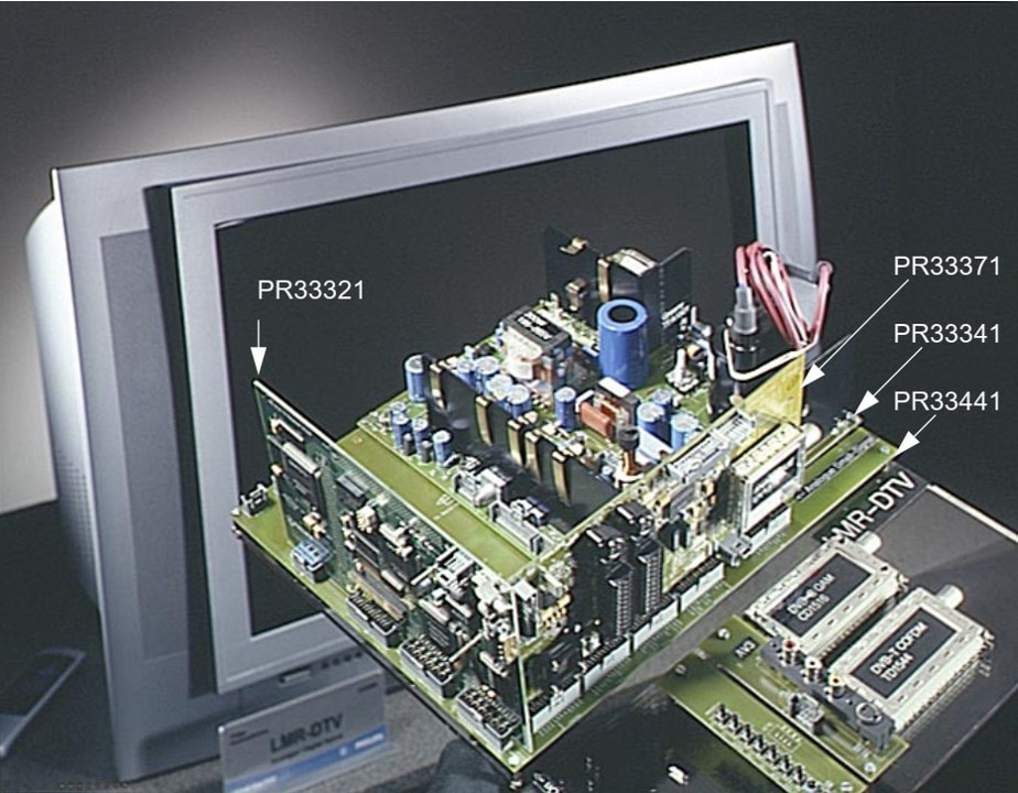
Picture of the boards inside the BOCMA-based hybrid TV receiver as show at the IFA1999. On the lower right board are a CD1516 cable tuner and TD1544 OFDM tuner.
[Philips Semiconductors AN99061]
|
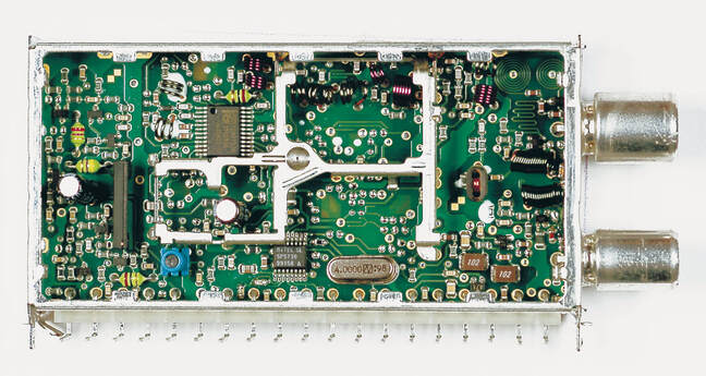
The Philips TD1544D/IH. On the right the dual input with at the bottom the DC/DC-converter. In the central section the empty VHF sections are visible. In the left section the OFDM BAW filter, discrete amplifier, W-AGC and the blue Sagami trafo for balanced IF output. Note that the low phase noise PLL is no longer from Plessey but Mitel. [via Darko Jancin]
|
It quickly became evident that the 1500-size tuners were too big, although they did provide good service during the early very low-volume days of OFDM introduction. A smaller module size was required, though, which was the 65mm WSP frame used for the UV1300A-Mk2. Compared to the now outdated TD1500 the TD1300 family introduced several new features:
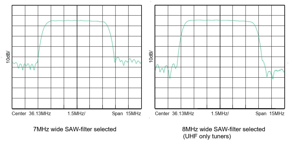
The switchable 7MHz (left) and 8MHz (right) SAW filters as measured inside the tuner. [Philips TD(M)1300AL Data Sheet]
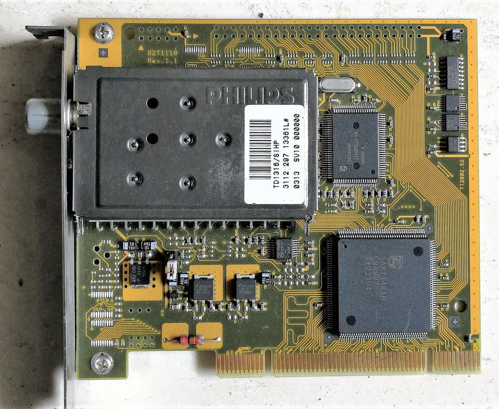
The new TD1316 on a typical PCI-card for digital TV reception on a PC. The two other large ICs are (top) the new TDA10045 OFDM channel decoder and (below) the SAA7143 source decoder and PCI bridge IC. Just below the tuner is the TDA9889 IF-to-low IF downconverter. [via Toh Kong Lim]
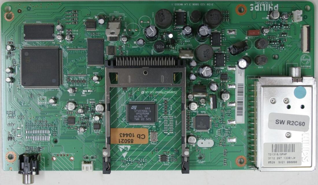
A second typical TD1300 application: DVB-T add-on boards for TV sets. Here the 2004 Intelligent Bolt-on (IBO) Zapper board of the LC4.3 LCD chassis 37PF5520. In the centre the Conditional Access (CA) card reader with STM card reader IC; right of this the QFP TDA10046 OFDM channel decoder. Upper left the PNX8316 Mojo MPEG2 decoder.
|
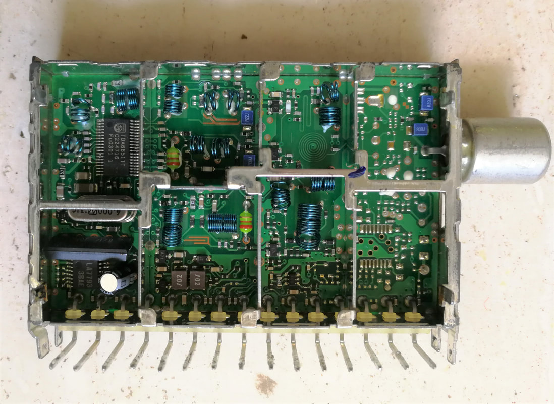
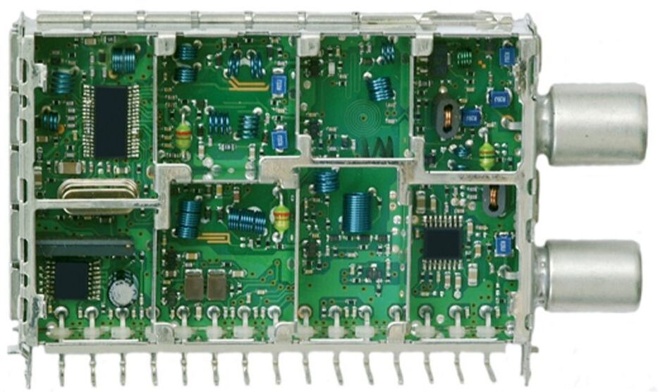
Interior view of the TD1316/SIHP. Upper left the MOPLL, lower right the empty slot for the modulator. Lower left the blue SAW filter and below it the Sanyo amplifier. The two grey blocks marked 102 belong to the DC/DC-converter. The type number suffixes SIHP refer to Symmetrical IF output, IEC, Horizontal mounting, and Power to RF input via pin1.
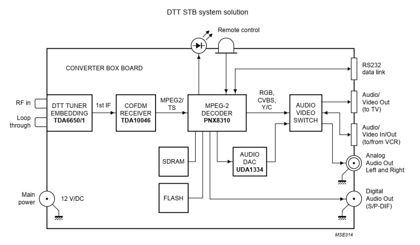
A DVB-T STB reference design around the TDA10046 and PNX8310, including the TD1316L tuner and its TDA6650 MOPLL. [Philips Semiconductors "DTT STB system solution" leaflet, 2003]
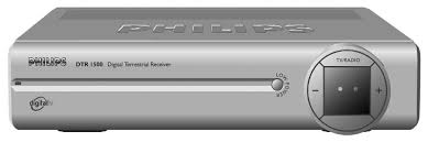
Philips Digital Networks also launched a family of Digital Terrestrial Set Top Boxes, the DTR family. This is the DTR1500 from 2002.
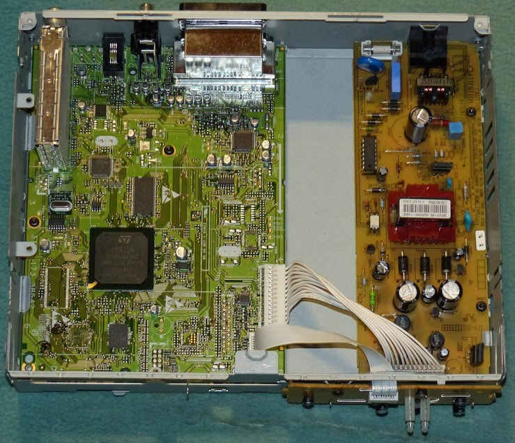
Interior view of the DTR1000, with upper left the TD1316L-Mk1. [Radiomuseum.org]
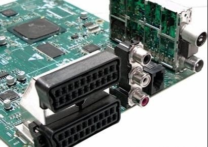
The TD1316L tuner on the DTR1500 main board. [Peter Vis]
|
The TD1300 appeared in 2002 and was quickly adopted in three application segments:
- PCI DVB-T cards. By this time Semiconductors had developed the new TDA10045 OFDM channel decoder, while the SAA7134 to 46 MPEG decoders and PCI bridge. Especially Semiconductors was a leading player in this domain, promoting many reference designs of these ICs including the TD1300. This was very effective because many customers used exactly this reference design (Hauppage, KNC, Asus).
- DVB-T STB boards. These could also be built using three main building blocks: the TD1300L, the TDA10045/46 channel decoder and the PNX8510-family MPEG2 source decoder. Especially Humax became a leading customer here. Like the VCR in the past also STBs required a loop-through and possibility of re-modulation, and this segment was the driver behind the TDM1300L, with modulator and loop-through.
- TV with DVB-T digital reception as an add-on feature. Philips Consumer Electronics and Semiconductors rather early aligned on the concept of dedicated Intelligent Bolt-on (IBO) cards very similar to STB boards but with interfaces to the BOCMA and Hip-Hop ICs of the main TV and based on PNX852x ICs. The first TV model to use such an IBO-board was the 32DW5658 based on the A10E, the (former) Dreux Mid End CRT chassis. The 2004 LC4 LCD chassis was the first to have DVB-T as an option throughout the chassis.
Block diagram of the TDM1300AL upgrade of the initial TD1300L family. Most options are around the RF in/output, in blue, with between brackets the indicator in the model's name. [Philips TDM1300AL Data Sheet, 2003]
It quickly turned out that two minor but essential updates of the TD1300 concept were required for optimal market acceptance:
- the modulator became an essential and default element of the module, allowing early STB solutions to operate the same way as previously the VCR, so with remodulation of the demodulated and decoded digital TV stream as a standard analogue signal on a UHF carrier. The standard product thus became the TDM1300.
- addition of an input Low Noise Amplifier (LNA) to compensate for the insertion losses of the many splitters and diplexers in front of the tuner. A wideband BFG540W bipolar transistor was used twice, once as input and once as output amplifier.
Rare interior view of the TDA1316L/IHP. From upper right clockwise: input section, the UHF modulator, VHF section, DC/DC-converter, SAW filter and IF AGC amplifier, MOPLL, UHF section. [via Edward Ng]
|
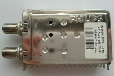
A strange animal: the TDM1331L/FHP36. As the name indicates the 31 refers to an NTSC receiver. However, the 36 refers to an IF of 36,15MHz. So, this was a PAL tuner modified for NTSC reception using the standard PAL IF settings.
|
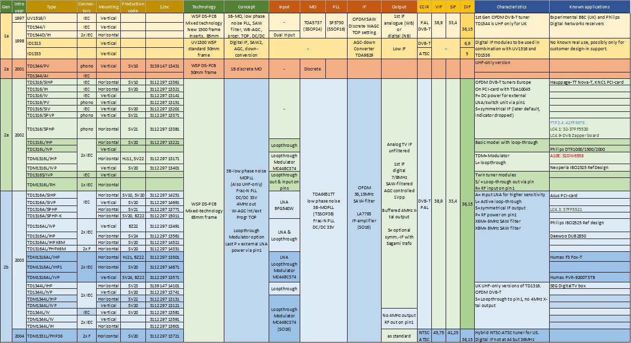
Overview of the first two generations TD1500 and TD1300 Philips DVB-T digital terrestrial OFDM tuners. Although initial production was sometimes Kwidzyn (manufacturing code HJ11 or 21), volume production was always in Singapore/Batam (SV20-24). Some main runners, mainly TDM1316s, were also transferred to Suzhou (BZ22).
Tuner Theory 15: Fractional-N PLL
Fractional-N PLLs were introduced for two reasons:
Standard tuner PLLs like the TSA5521 and 5523 used an internal reference frequency of 7,812kHz, which was obtained by dividing the 4MHz reference crystal frequency by 512. The wanted LO frequency was generated using a divider ratio of 8N in the main loop (so fixed divide-by-8 plus programmable divide-by-N). Therefore, the LO frequency step size was 8 times 7,812=62,5kHz. In case of a different step size a different crystal frequency was required. See the PLL introduction in Chapter 4. The phase noise of the PLL is the phase noise of the (4MHz divided by 512) comparator frequency multiplied by 8N. The phase noise of the LO is thus 20log(8N) dB higher than that of the reference. For the lowest UHF channel 21 (474MHz) we find 8N = 7904 and the phase noise penalty of 78dB.
- better phase noise
- adaptability to different standards
Standard tuner PLLs like the TSA5521 and 5523 used an internal reference frequency of 7,812kHz, which was obtained by dividing the 4MHz reference crystal frequency by 512. The wanted LO frequency was generated using a divider ratio of 8N in the main loop (so fixed divide-by-8 plus programmable divide-by-N). Therefore, the LO frequency step size was 8 times 7,812=62,5kHz. In case of a different step size a different crystal frequency was required. See the PLL introduction in Chapter 4. The phase noise of the PLL is the phase noise of the (4MHz divided by 512) comparator frequency multiplied by 8N. The phase noise of the LO is thus 20log(8N) dB higher than that of the reference. For the lowest UHF channel 21 (474MHz) we find 8N = 7904 and the phase noise penalty of 78dB.
|
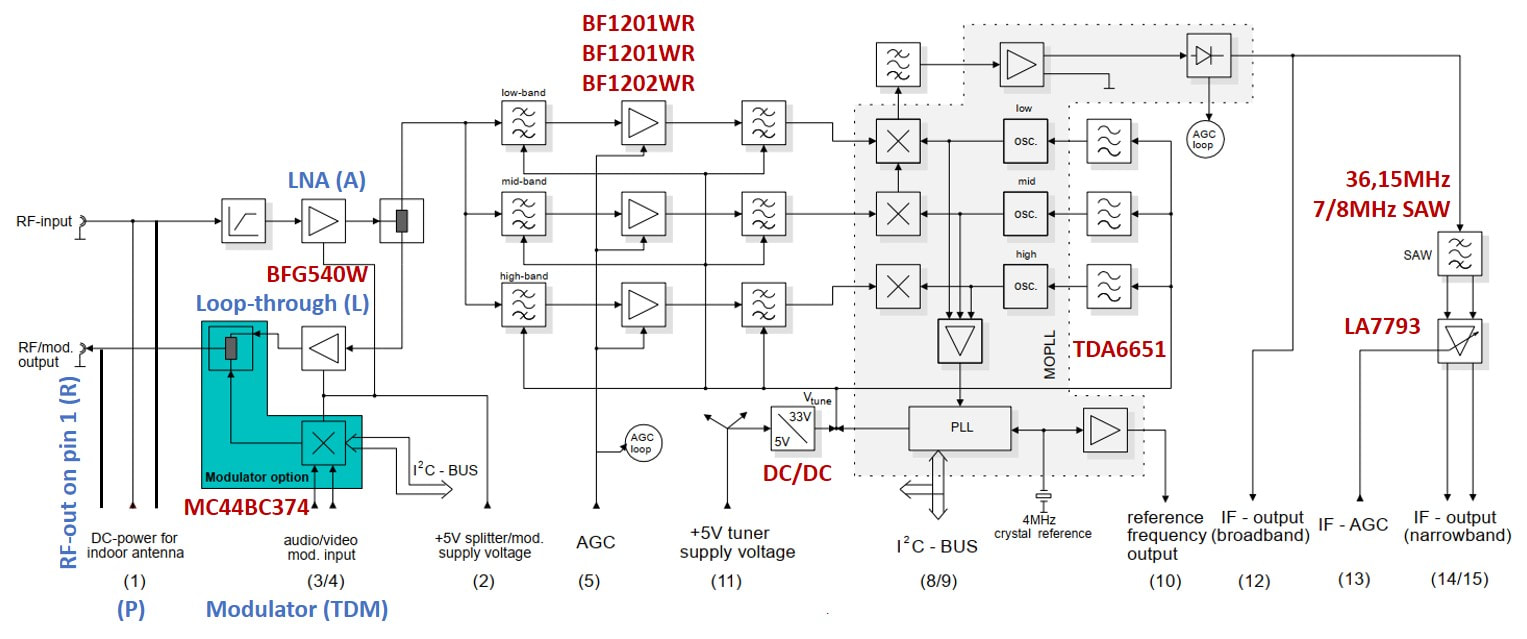
Reducing N thus makes a lot of sense for phase noise reduction, critical for OFDM reception. In the TDA6651 PLL two major changes were introduced: the phase detector frequency increased from 7,8kHz to 1, 2 or 4MHz. Secondly N became fractional k/q, with k and q both programmable. Fractional dividing ratios are obtained by ignoring pulses in so-called bit-swallowing counters. The total divider ratio now became (N + k/q) and the total PLL equation Flo = (N + k/q) * fcomp.
|
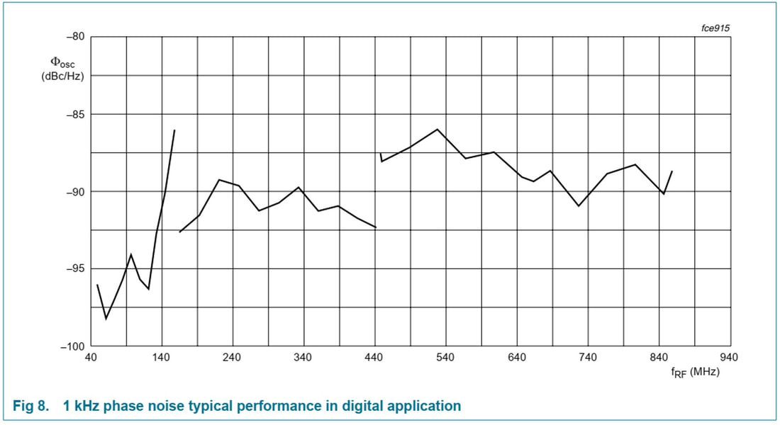
Typical close-in 1kHz phase noise in the different bands of the TDA6651 fractional-N PLL. [Philips Semiconductors TDA6651 Data Sheet]
|
For DVB-T in the UHF band channel width is 8MHz and the channel centre frequencies are given by
474 + (M-21)*8 [MHz] with M the channel number from 21 to 69. The LO frequency is 36,15MHz higher, and thus 510,15 + (M-21)*8 [MHz]. If we take the first channel (M=21) and the highest possible comparator frequency of 4MHz we get:
510,15 = (N + k/q) * 4 [MHz] where N, k and q must be integers. Now 510,15/4= 127,538 = (N + k/q). It can be proven that N=127, k=13 and q=24 is a very good approximation to this solution.
The result of all this is now a step size of fcomp/q = 4MHz/24=166,67kHz, a divider ratio N that is 8 times (18dB) lower than the 8N from the classical PLL. Especially close to the carrier (1kHz) this improvement is manifest, exactly where the phase noise contribution is highest.
Similarly we find for
ISDB-T: 4MHz, k=1, q=28, step size 142,86kHz
ATSC: 1MHz, k=0, q=20, step size 50kHz
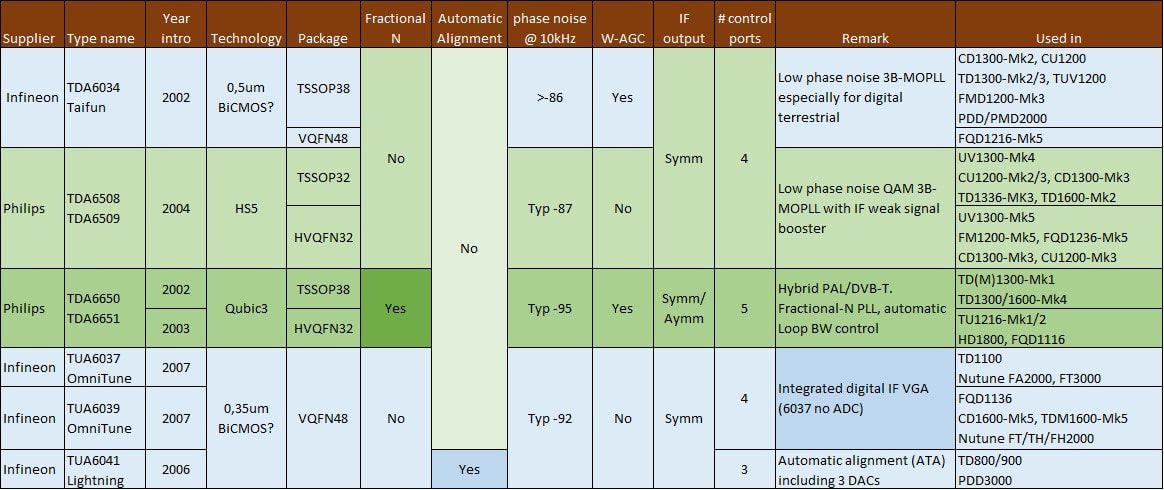
Overview of the different MOPLL ICs used in BU Tuners and BL RF Solutions and Nutune from the year 2002. After the TDA6650 fractional-N PLL Philips stopped developing tuner MOPLLs, nstead focussing on Si Tuners. Infineon, in contrast, brought out a last family of MOPLLs in 2006/7 focussing on higher functional integration.
ATSC 8-VSB digital terrestrial TV in the US, 1998
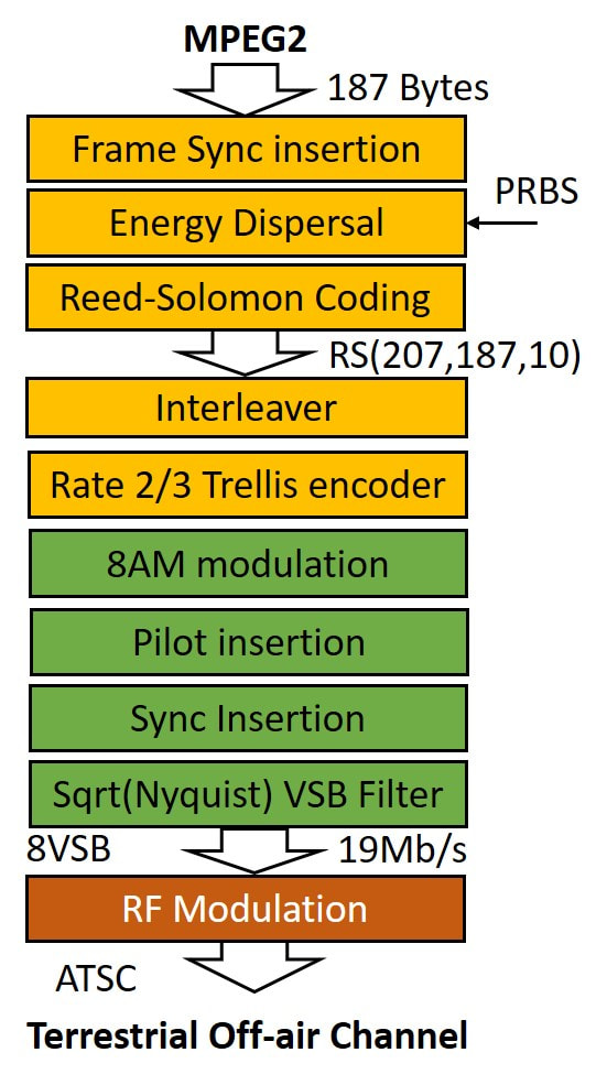
Upstream encoding (yellow) and modulation (green) of ATSC 8-VSB digital TV.
|
Parallel to the dominant European digital TV standardization (DVB-S, DVB-C and DVB-T) the US drove its own standards through the Advanced Television Systems Committee (ATSC) for two main reasons: politically it could not accept the European dominance in the standard setting, while secondly the US broadcasting (NTSC) suffered from the 6MHz channel bandwidth, defined back in 1941 when that was still considered large enough. To come to roughly identical digital transmission capacity per channel required higher order modulation schemes. As already introduced in the DVB-C section the US Cable solution was straightforward: instead of the DVB-C 64-QAM the US standard became 256-QAM, achieving 38,7Mb/s in a 6MHz channel. For all clarity, this was not an ATSC standard, but driven by the ANSI Society of Cable Telecommunications Engineers (SCTE). Because in the US every cable operator is legally allowed to select its proper solution, 256-QAM became the de facto standard.
|
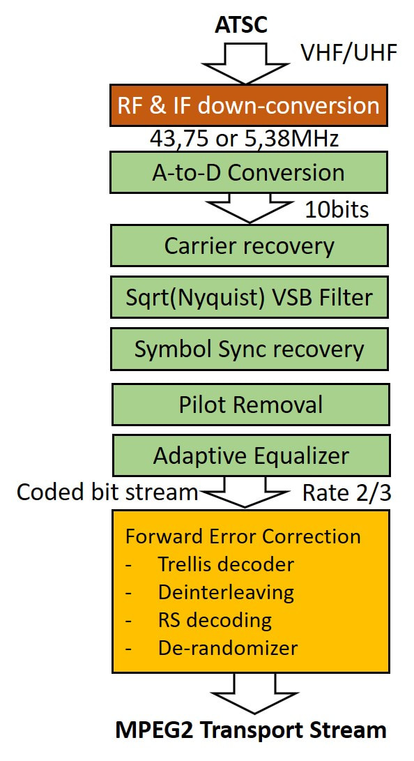
Downstream demodulation and decoding of ATSC 8-VSB digital television.
|
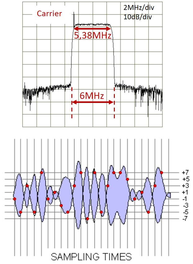
The spectrum of 8-VSB (top) and time domain signal (bottom). Due to the Nyquist filtering the signal is always at one of the 8 levels at the moment of sampling. [Sparano]
|
The ATSC standard started back in 1993, when the FCC triggered the creation of the Grand Alliance, a consortium of the main US electronics and communication players (not necessarily US companies, Philips also participated, next to AT&T, General Instruments, MIT, David Sarnoff Research, RCA-Thomson, and Zenith) to define standards for HDTV and its transmission. However, standards setting in the US is a different process than in e.g., Europe or Japan, where it is mostly left to the technical community to come with consensus on the "optimal" technical solution, which is then possibly twisted by politics when the French or British have their usual objections. The Grand Alliance, in contrast, was not a consensus-driven exercise, but the big players simply divided the tasks amongst them based on eagerness, claims or lack of others interested. Since Philips was mainly interested in harmonizing the HDTV formats, the transmission standard was left to Zenith, the last remaining US TV maker, which promoted its 8-VSB concept. (A similar single company driven standardization would happen a few years later with the Qualcomm CDMA standard for 3G telecom). It was accepted and published by the FCC as standard A/53 in 1996. Interestingly, in 1995 Zenith, nearly bankrupt, was acquired by Korean Lucky Goldstar Electronics (LG), so in the overviews of 8-VSB patent owners you will find this company at the top of the list.
The 8-VSB modulation is most similar - but also very different - to QAM, so we'll compare it with that standard. The encoding part of ATSC A/53 is fortunately very similar to DVB-C, with a slightly different Reed-Solomon. A Trellis-coder translates 2 bytes into one 3-bit byte, which is used for 8-level Amplitude Shift Keying (8-ASK). For ease of clock recovery, a pilot is inserted by creating a DC offset, followed by Segment (208 bytes) and Field (313 Segments) sync bytes insertion. |
|
At this point the signal is a 10,76MSymbols/s classical 8-ASK double side band signal with pilot carrier and several rapidly diminishing side lobes. This signal is now applied to a rigorous square-root Nyquist filter, eliminating all signal left of the carrier, and reducing the signal bandwidth to just half the symbol rate: 5,38MHz. With a roll-off relaxation of 11% this is equal to the 6MHz NTSC channel width.
Although this method allows to squeeze 19Mbit/s into a 6MHz radio channel, the effect of the Vestigial Side Band (VSB) asymmetric filtering on the signal waveform is serious: major phase and amplitude distortions happen due to ringing of the individual symbol filter responses. There is only one escape for proper detection: when clocked with the symbol rate frequency all these filter responses are orthogonal - like in OFDM - meaning that they are all equal to zero at all sample moments other than their own. This results in a small yet open eye pattern, so far assuming no multi-path fading. At the same time the peak-to-average ratio of the signal is high, requiring a roughly 10dB back-off in the transmitter and receiver to avoid non-linear distortion. 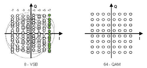
An 8-VSB constellation diagram (left) and 64-QAM (right). Where QAM uses both the I and Q axis for encoding, 8-VSB only uses the real axis for amplitude modulation. However, due to the VSB filtering phase distortion can move the constellation points along the Q axis. In the example all green constellation points should be detected as +7 (111). [All 8-VSB illustrations in this section are from Sparano "What exactly is 8-VSB anyway?", a very useful introduction to the standard.]
|
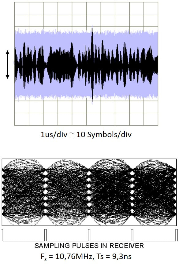
Two views at the received time domain 8-VSB signal. The top graph shows an instantaneous trace (black) and a time-averaged trace (purple). Below the eye pattern. [Sparano]
|
From the moment the Grand Alliance, ATSC and FCC (in that order) standardized 8-VSB a heated debate emerged: why choose an unsophisticated VSB scheme when the rest of the world was convinced OFDM was by far the best solution for dealing with multi-path fading? The FCC maintained VSB to be more robust to fading, while also better in so-called fringe areas with low received power. The latter is true if 9m high antennas are used, a solution more common and acceptable in the US than in Europe and Japan, where large external aerials are often forbidden. To compare 8-VSB to OFDM on multi-path robustness tests were done, although allegedly using non-optimal OFDM receivers. It is a fact, though, that the first VSB demodulator ICs like the Philips Semiconductors TDA8960, could only compensate echoes between -2 and +10ms, whereas DVB-T OFDM allowed -100 to +100ms when using the maximum guard interval. Only after 5 to 6 generations of VSB decoders the echo equalizer performance came at roughly half that of OFDM. But whatever the technical outcome would have been, the FCC never intended to adopt OFDM simply because they wanted their own standard, even at lower performance.
|
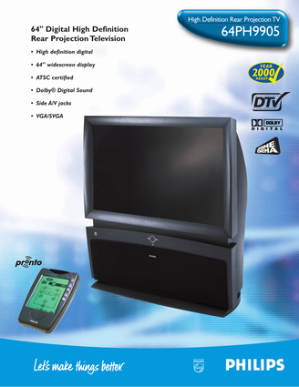
It should not be forgotten that ATSC A/53 specified both a terrestrial system - using 8-VSB - and a cable system - using 16-VSB given the better SNR on cable networks - but the latter was largely ignored by the cable operators, deploying 256-QAM instead. VSB would thus be limited to off-air reception in the US, Canada, and a few Caribbean and Pacific islands. Because of all discussions about the technical merits of 8-VSB, deployment started very slowly, despite a lot of political pressure, first transmissions taking place in 1998. Obviously, Philips, as member of the Grand Alliance, was eager to participate, both with modules (BL Tuners!), ICs (Semiconductors), Set Top Boxes (Digital Networks) and TV sets (CE-BGTV). To this end a dedicated development lab was created in Briarcliff (New York) near the US Philips Research Lab there. In 1998 and 1999 Philips was one of the first brands to release ATSC-ready sets. These were super high end HDTV 64" rear projection sets from Brugge, the 64PP9901 and 64PH9905, both almost certainly based on the GFL2 chassis.
The outcome of all these developments was that also for digital TV the US continued to require its dedicated tuners. |
TD1536 and FCV1236, the first ATSC support, 2000
As member of the Grand Alliance and eager to be a leading player in the worldwide HDTV roll-out, the company pushed hard to get a first ATSC-ready set out by the time the standard was released, and experimental transmissions started. The BU Tuners, like the OFDM developments taking place in parallel, used the 1500-platform for these emerging digital standards. For ATSC this was the TD1536, conceptually identical to the TD1516 for OFDM but with the IF at 43,75MHz or 44MHz in line with the standard NTSC intermediate frequencies (45,75MHz Picture Carrier and 41,25MHz Sound Carrier). The TD1536 was used in the 64" rear projection TVs introduced above, developed in Brugge based on the GFL2 chassis. The NTSC receiver used the standard FQ936-(Mk2) analogue front end. It likely used a PS1311 RF splitter, and - so far not formally confirmed - was possibly the only time the ID1333 second IF module was actually used in a product.
The Philips TD1536D/F, dual input ATSC tuner. Lower right the DC/DC-converter, in the leftmost section the IF SAW filter and amplifier. [via Darko Jancin]
|
Still based on the proven TDA5737 MO and TSA5523 PLL the tuner offered high performance with respect to phase noise and tilt. The DC/DC-converter for supplying the 33V varicap bias, copied from the FQ1200 multimedia frontends, was an important feature for PCI applications. The dual inputs allowed the tuner to be connected to both an off-air antenna as well as the local cable distribution, also because it could handle both 8-VSB and 256-QAM modulation.
|
Although the super high-end TVs were publicity-wise a good show, initial volumes were not in TVs with ATSC boards. Especially in the US the PC market was much more eager to start experimenting with the new technology, and PCI-cards thus required ATSC tuners. Philips Semiconductors and the BU tuners jointly brought out the "Coney" Reference Design, based on the latest solutions shown in the block diagram. The first to apply this architecture in a product was Hauppage, with its WinTV PCI-card. As in the first TVs this was a high performance solution, unsurpassed by any competition, but with one major drawback: the size of the module. A functional shrink was urgently required.
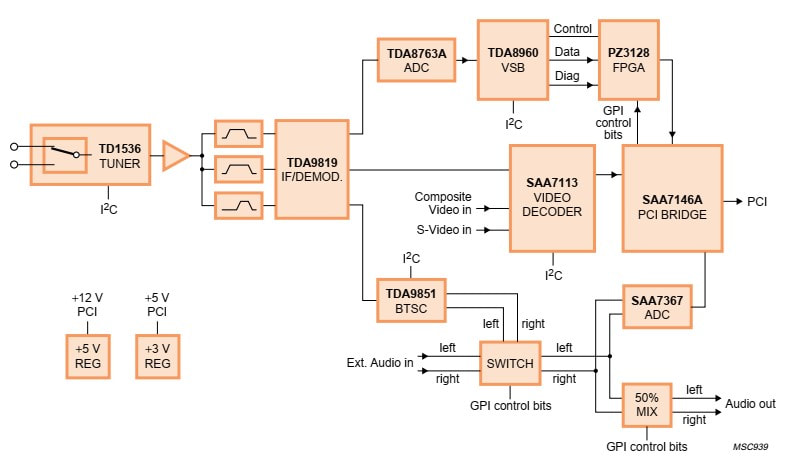
Block diagram of the Philips Semiconductors "Coney"ATSC reference design for PC applications. The TD1536 tuner and TDA8960 8-VSB channel decoder were the ATSC-specific new components. [Philips Semiconductors Coney leaflet, November 1998]
|
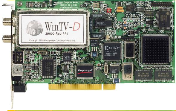
Hauppage WinTV ATSC/NTSC PCI-card, the first to implement the Coney reference design including the TD1536D/F. Note the still very low level of integration, resulting in many different ICs on the board.
|
Block diagram of the FCV1236D. Note the switchable input and the dual 44MHz VSB SAW filters. [FCV1236D PRS document, via Toh Kong Lim]
Interior view of the FCV1236D/FH. The IF section has the TDA9829 VSB down converter on the B-side, as well as the four SAW filters and two orange sound filters. The high isolation RF switch therefore had to be crammed between the standard tuner and the two connectors. [via Darko Jancin]
|
Because at this point the PC application was driving developments, the need for backward compatibility with analogue-only reception was determined by this domain. Which obviously was the FQ1216-Mk2 family of Multimedia Front ends. The most recent product was the FQ1216ME-(Mk2) using the Quasi Split Sound (QSS) IF demodulator IC TDA9818 for positive and negative video modulation. No QSS NTSC version had been developed yet but using the tuner section of the FM1236 and the negative modulation-only TDA9817 the analogue core of a combo NTSC-ATSC front end was available. To this was added the IF path originally contained in the TD1536 and ID1333: two 44MHz VSB SAW filters with buffers followed by the TDA9829 second down-converter. Three versions were foreseen:
|
|
The biggest challenge of the FCV1236 was the dual input, and especially the extreme input-to-input isolation mandated by the FCC of 80dB up to 216MHz and 55dB from there to 801MHz. This was an extremely demanding requirement, especially in the crammed space left for the switch within the 1200 frame. The "standard" solution with common anode diodes did not provide sufficient isolation, so in the end a second RF switch had to be added. This was made in the at the time quite revolutionary new Silicon-on-Sapphire (SoS) technology developed by Peregrine Semiconductors. Due to the sapphire substrate, ground- and substrate parasitics were effectively eliminated. Although the IC initially cost 1,50USD this was deemed acceptable given the healthy margins on these products. All in all, it was a serious struggle to meet the specs, although it did provide a patent.
The FCV1236 started sampling to the different channel decoder players (Oren (from Israel) Broadcom, NextWave (a spin off from Sarnoff Labs) in 2001, but it took till 2003-4 before volumes became interesting, mainly due to a joint demonstrator with NextWave at the 2003 Consumer Electronics Show (CES) in Las Vegas. It was all simply too new, there was limited content, and the supply base was unstable: NextWave was acquired by ATI in 2002, Oren in 2004 by Zoran. In 2003, following the closing of Philips Sunnyvale, also Philips Semiconductors stopped ATSC channel decoder development. Some of these decisions were amplified by the fact that ATSC take-off was very slow until 2005, making it an expensive field to play, with high requirements and investments but minimal sales. |
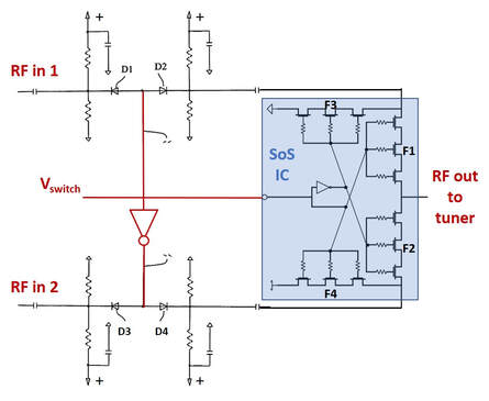
Circuit diagram of the I2C-controlled RF input switch for the FCV1236. In case Vswitch is high D3 and D4 are in reverse, drawing no current and blocking input 2. D1 and D2 are open, providing a low-Ohmic RF path to the Peregrine Silicon-on-Sapphire (SoS) IC. Here series FETs F1 is open, providing the path to the output. F4 is also open to short circuit input 2 to ground, while F2 and F3 are closed and provide high-ohmic resistances. For Vswitch = low the opposite situation applies.
|
The first two generations of Philips tuner-frontends for 8-VSB ATSC: the TD1536 and FCV1236.
Satellite Developments, 2000-2005
|
By the turn of the century the satellite broadcast market was rapidly stabilizing. Within a very short time all main operators had switched from the analogue FM to digital QPSK transmission, mostly DVB-S or DSS in the US, the main reason being the much higher number of channels that could be transmitted over the same transponder. However, the absolute share of satellite in the TV distribution market was not increasing, remaining at around 25%. Growth came only from the total TV market growth of some 3-4% per year. The 2000 volume was around 23Mio boxes (8 Mio Europe, 12Mio US and 3Mio Asia-Pacific), growing to some 36Mio by 2005.
On the satellite operator side consolidation was taking place. In Europe SES with its Astra satellites became the dominant player, with Sky (UK and Ireland), Premiere in Germany (using Eutelsat) and Türksat (Turkey) as smaller players. In the US DirecTV became dominant. The Astra2 series of satellites now typically transmitted over 32 transponders of 28MHz channel width. |
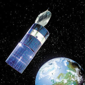
Astra 2D satellite, based on the Hughes601 spin-stabilized platform. It was launched June 16 2001 on top of a Proton rocket from Baikonour in Kazachstan.
|
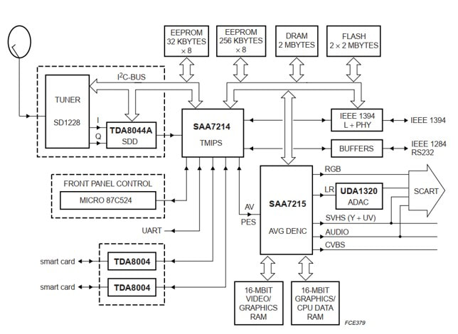
Block diagram of the Philips Semiconductors STB5860 Satellite Set Top Box Reference Design. The SAA7214 is the MPEG decoder, demultiplexer and Conditional Access controller. Except for IEEE1394 all interfaces are still analogue (SCART) provided by the SAA7125. [Philips Semiconductors OM5730 Data Sheet, 1999]
On the device side the Philips business selling Set Top Boxes was Digital Networks (DN), still driven by Rob van Oostenbrugge. This business , with its main development centres in Eindhoven, Suresnes (France) and Sunnyvale (CA, USA) and internal production in Hasselt (Belgium), had grown to 1Bio€ sales in 1999, with outlook on 1,5Bio€. It had obtained, at a 12% market share, the number 2 world-wide position in Set Top Boxes, behind General Instruments (which dominated the US Cable market, 18%) and before RCA/Thomson(which dominated the US Satellite market, 11%). DN was the leader in Europe, especially in Satellite through its main customer Astra, but was growing its business with Echostar and DirecTV in the US. Despite all this, business in STB was tough, for the reason mentioned above: a (low end) STB essentially reduced to the front end function including the channel decoder, a single MPEG demux/encoder and a power supply. Furthermore, all customers demanded their dedicated Conditional Access solution (CA, the smart card with subscription key). Consequently, Philips increasingly used ODM boxes from low end STB makers like Pace (UK), while under pressure of cost reduction they drifted away from Philips Semiconductors to ST Microelectronics, which was becoming the market leader in STB functional integration and the main supplier to market leader RCA/Thomson. Both these trends worked out negatively for the BU Tuners, which saw itself replaced by Alps in more and more platforms.
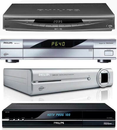
Four generations of Philips Digital Networks Satellite Set Top Boxes. From the top:
(1) DSX6073 Gold Box (2001) 27,5MS/s, produced Hasselt;
(2) DSR2015 for Premiere (2003), probably a Pace ODM box, introduced DiSecq1 LNB control;
(3) DSR2210 (2004) for Dutch Kanaal Digitaal;
(4) DSR5005 (2006) for DVB-S2 MPEG4 HDTV.
[Sat-Receiver-World.de]
|
Throughout the previous chapters it has been made evident how especially the developments in (silicon) semiconductor technology have been driving product architecture and concepts. Although on the one hand this allowed continuous size and price reduction, the integration also steadily simplified the integral RF design. Many previously complex functions requiring solid RF design knowledge, like oscillators, filters and mixers became integrated and part of the ICs, making the application design around them much easier. The domain where this happened first and foremost was satellite reception. Because of the well-defined and stable transmission path from satellite to receiver, with modest dynamic range requirements, minimal interferers and linearity requirements, satellite reception was the easiest domain to push for total integration.
However, this integration trend not only happened on the front end side of the system, but the digital back end was also integrating at an even higher speed, pushed by the 2,5 year cycle of CMOS node migration. By the turn of the century the standard CMOS node within Philips Semiconductors had become 180nm, with 120nm a weak node that was rarely used. In the partnership with ST Microelectronics in Grenoble (France) 90nm was being developed and rolled out, marking the transition from 200mm (8") to 300mm (12") wafers. This provided a path for continuous integration of all digital functionality, and Philips Semiconductors was an active player in all this. 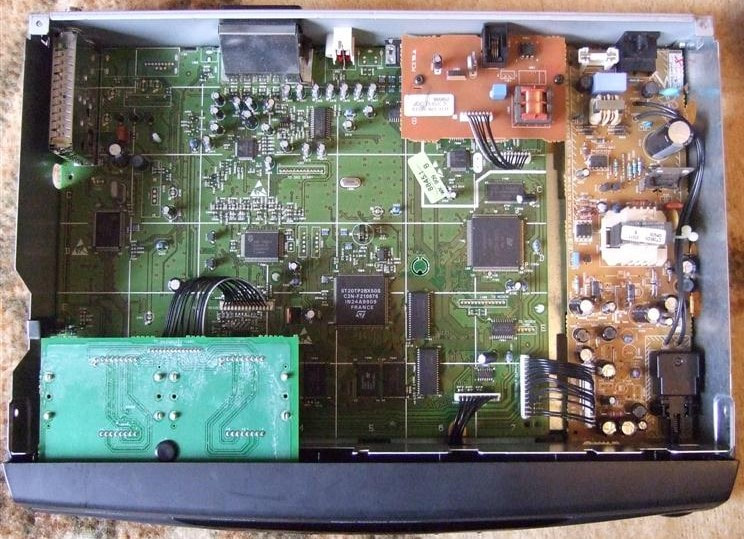
A major business success of Philips DN, the DSX6000 "Gold Box" family of Satellite STB from 2000. Upper left the SD1228/L-Mk3 front end with loop-through function. [GbC-Net forum]
So in the end both Digital Networks (from the top) and BU Tuners (from the bottom) were squeezed between the reducing sales prices of Set Top Boxes and the growing semiconductor content, leaving hardly any margin for the module maker and set integrator. And this in a domain where developments went extremely fast, with new - even more integrated - chip sets every year, demanding a substantial development effort. Not to forget the growing number of services, copy protection (Philips used Macrovision), new concepts like Astra Multimedia Home Platform (MHP), DiSEqC LNB control and towards 2005 the new standard DVB-S2, based on MPEG4 H.264 HDTV video encoding and using 8PSK (or higher) modulation.
In 2002 DN was hit by the same re-organisation that dissolved the PD Components, which meant that all US STB activities from Sunnyvale were discontinued. In Europe manufacturing in Hasselt was closed and transferred to Szekesfehervar in Hungary. In 2004 DN was dissolved as a Business Group and the remains of the STB business integrated into the new BG Home Entertainment Networking under Consumer Electronics. The BU Tuners/RF Solutions did not fare much better, and after a last effort with Network Interface Modules, also had to throw in the towel in the domain of satellite. |
SD1200-Mk3, 2000
Although the year before, 1998, the SD1200-Mk2 family was released, developments in integration went so fast that already the year after the Mk3 generation had to follow. Where the Mk2 had made major integration steps with the TDA8010 mixer-oscillator and TDA8024 IQ IF demodulator, the introduction of the TDA8060 Zero-IF (ZIF) MO made both these ICs immediately obsolete. With the ZIF architecture Intermediate Frequencies are reduced to DC, and the MO output can, after proper low pass filtering and amplification, be fed directly to the ADC inputs of the channel decoder. Furthermore, with the ZIF architecture tracking was reduced to having the input BPF and the LO tank circuit centred at the same frequency, much easier than tracking at 480MHz distance. Even the application of the TSA5512 PLL was reduced to its core function since any switching or AFC could be omitted.
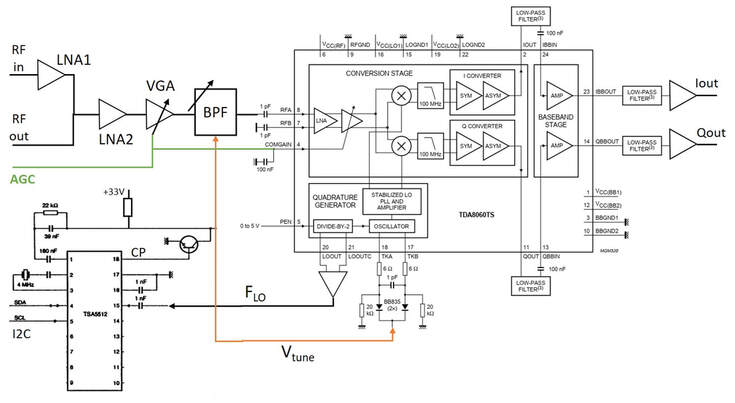
Block diagram of the SD1200/L-Mk3. The RF function has reduced to a few amplifier stages and the tunable BPF. The AGC control signal comes from the channel decoder.
Tuner Theory 16: Zero-IF receivers
From the first TV tuner in 1951 till the year 2000 all tuners and receivers that have been presented were based on the heterodyning principle: the Local Oscillator (LO) frequency is off-set (usually above) the incoming RF signal, producing, when mixed in a non-linear device, the difference Intermediate Frequency (IF). One of the main difficulties of tuner design over all these years was the required frequency-dependent filtering: RF Bandpass Filters (BPF) before the mixer and fixed SAW filters in the IF. The challenge was good filter performance across substantially large tuning ranges. Not only did this require a lot of detailed RF design knowledge, the cornerstone of the Tuner business, more importantly these filters are impossible to be integrated in silicon devices. This is mainly due to the high RF signal path losses on silicon, caused by the lossy substrate, which limits the attainable Quality factor of inductors, which in turn means (RF BPF) filters on silicon show high insertion loss. Finally, when trying to increase the filter Q, the inductors tend to become relatively big, making them expensive in advanced silicon technology. It was therefore obvious that, to push receiver integration, the classical heterodyne architecture had to be replaced by one that supported (almost) full integration.
The solution to this is the so-called Zero-IF (ZIF) concept, although it is equivalent to the more classical terminology "coherent receiver" or "synchronous detector". In all cases the concept is the same: the incoming RF signal is mixed with an LO of the same frequency, thus resulting in an IF equal to zero Hertz. When the RF signal was modulated, the modulation will now be around DC in baseband. Furthermore, when this is done with two coherent orthogonal In-phase (cosine) and Quadrature (sine) components of the LO, the two outputs effectively deliver the I and Q (or real and imaginary) modulation components. See the figure below. 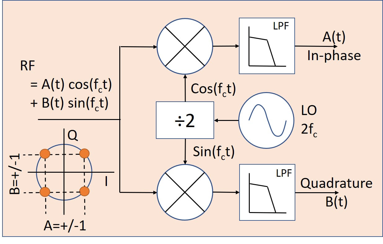
The Zero-IF concept.
From the above diagram the advantages are evident: no (tunable) BPF anymore, only easy to integrate LPF and the sine and cosine LO components are easily generated in a divide-by-2 circuit. A few remarks, though: for proper matching the RF input still requires some broadband matching filter; the Noise Figure of the mixers is very bad, requiring an (external) LNA; proper I-Q phase alignment is very critical and might need active control; the LO usually still requires an external tuned tank circuit. Also, the LO phase noise requirements are higher!
ZIF was first implemented in Philips DECT cordless phones, followed by the narrow band 2G and 2,5G GSM receivers. Satellite was the first wideband application using ZIF. |
There was now more than enough space on the B-side for all SMD components, while the number of manually placed components reduced to two: the X-tal and a charge pump capacitor. The wave soldered A-side was essentially empty and only used for DC distribution and grounding.
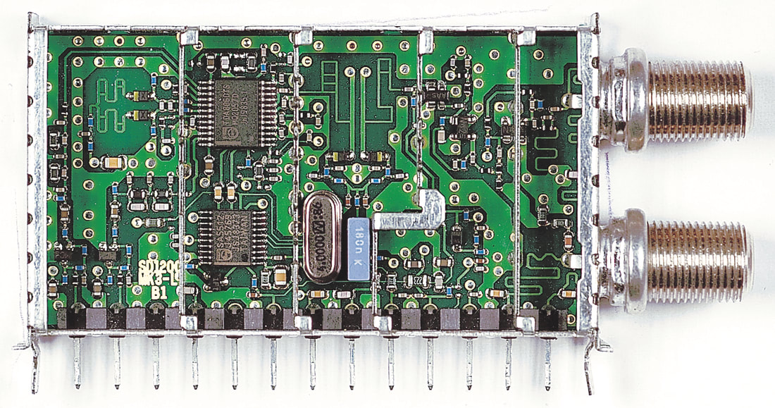
B-side interior view of the Philips SD1228/L-Mk3 satellite frontend. The upper F-connector is the input, the lower one the loop-through output. The second section contains the LNAs, the third one the tunable planar BPF (note the two varicaps at the foot of the filter), the fourth section the ZIF-MO and PLL, and the leftmost section the symmetrical LO tank circuit (again with 2 varicaps) and the output LPFs (discrete) and amplifiers. [via Darko Jancin]
In parallel to the SD1200-Mk3 for digital satellite, a very last analogue FM satellite front end was released, the SF1218D-Mk3, using the same ZIF architecture and chip set. In fact, with the ZIF architecture analogue and digital receivers had become identical, apart from minor details like the bandwidth used.
Another special version was the SD1278-Mk3, like its Mk2 predecessor specifically for bitrates as low as 1MS/s. This required the TSA5059 low phase noise PLL, which allowed much higher comparison frequencies to reduce the divider multiplied phase noise. With five I2C-controled bits the phase comparator frequency, and thus the PLL step size, could be selected between 12,5kHz and 2MHz. This PLL would also become the standard PLL in the next generation. 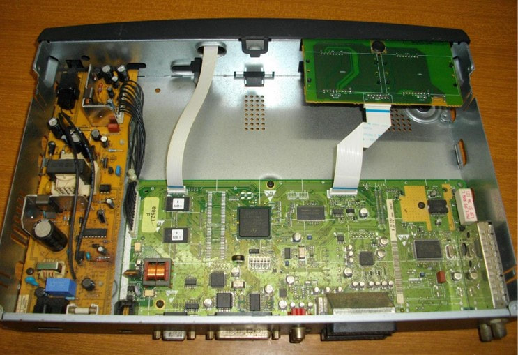
The SD1228/LH-Mk3 in the Philips DSX6073 Gold Box Satellite STB introduced 2001. Note that the box is becoming very empty. The largerst IC on the board is the ST Omega MPEG decoder. [Radiomuseum.org]
The SD1200-Mk3 family was still reasonably successful, being used in all DSX5000 to DSX7000 Philips DN Set Top Boxes. However, both were suffering from severe added-value reduction, and thus margin pressure. From 2000 to 2002 the satellite sales of the BL reduced by a factor two; something needed to be done.
|
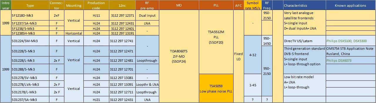
Overview of the Philips SF/SD1200-Mk3 satellite front ends family. The production code HJ indicates they were all produced in Kwidzyn, Poland. This family was mainly used in the Philips Digital Networks satellite STB range.
SU1278, the first NIM, 2001
Satellite RF and IF functional integration was thus happening very fast, at this stage (around 2000) reducing the satellite front end to just two ICs (a ZIF MO and a PLL) with limited RF application around it. And coming soon was the next integration step, the ZIF MOPLL on which Philips Semiconductors (the TDA8260), Infineon (TUA6100) and ST Microelectronics were all working. With both sales price and margin reducing, some form of functional integration was needed to add value back to the module. The answer was the Network Interface Module (NIM), the integration of the RF and channel decoder functionality into one module, thus delivering a very convenient RF-to-MPEG Transport Stream converter. The NIM had several advantages:
- Customers in principle did not need to bother about any functionality related to the transmission, channel, RF settings, etcetera. When properly set, only the desired channel must be sent to a NIM, the mother board system only taking care of conditional access, MPEG decoding, demultiplexing and conversion to the output interface format.
- All front end related control loops are contained within the NIM: AFC, AGC, clock synchronisation. It also allows sharing of resources like the 4MHz crystal.
- It avoids most sensitive analogue interfaces, reducing the interfacing to I2C for control and MPEG2 TS as output. (In most channel decoders the TS was available both in serial and parallel format).
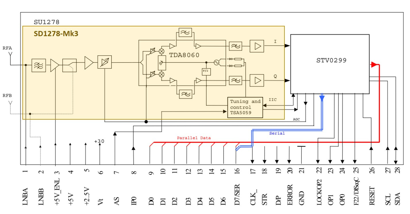
Block diagram of the Philips SU1278 satellite NIM. The yellow section is functionally identical to the SD1278-Mk3 front end. [Philisp SU1278 Data Sheet, August 2001]
|
The first satellite NIMs by the BU were based on the 1500 frame, but these were clearly too large (or too early) and it was decided, also because most customers were in the PC-card and STB domain, to switch to the short - 67mm - 1200 frame, although adapted to the mixed technology. The front end sections were copied 1:1 from the SD1278-Mk3, using the TDA8060 ZIF-MO and low phase noise TSA5059 PLL. This gave the SU1278 a range of 1-45MSymbols/s, since all Nyquist filtering was done digitally in the channel decoder.
|
As channel decoder the ST STV0299 was selected, which was becoming the dominant IC in the market. Philips Semiconductors was also active but suffered from the integration with VLSI in 1999. With that came a design centre in Rennes, France, from the former company Comatlas which was acquired earlier by VLSI and had a larger portfolio of channel decoders than Philips. It was decided that all channel decoder development would be concentrated in Rennes, but the usual internal politics delayed the process. It therefore took a while until the original VLSI VES1993 and Philips TDA10085 had merged into the new TDA10086. Which turned out to be a good IC, quite successful in the market, but too late for the SU1278. And thus the ST IC was selected. Apart from offering the by now standard variable rate QPSK channel decoding, with two on-board ADCs, it featured additionally:
- the STV0299 acted as I2C repeater for the tuner section. Because the low phase noise PLL was very sensitive to I2C crosstalk, it should be disconnected from the main I2C bus when stabilized. The I2C bus was therefore routed through the channel decoder, which would disconnect the output during normal operation. Only when a different channel had to be selected the bus would be made available to the PLL.
- the STV0299 contained a DiSEqC signal generator for control of the LNB, the details of which will be explained in the next LNB section.
- the PLL and channel decoder shared the same 4MHz crystal.
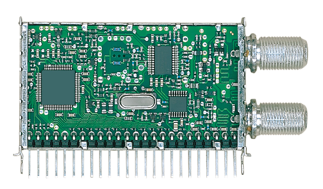
Unfortunately, I have no pictures of the Philips SU1278 interior. The picture shown her is NOT the final product, only a prototype, although the circuit lay out probably comes close to the final design. The main differences are the lack of internal frame screens, while this prototype has only 24 pins. The final product had 28. [via Darko Jancin]
|
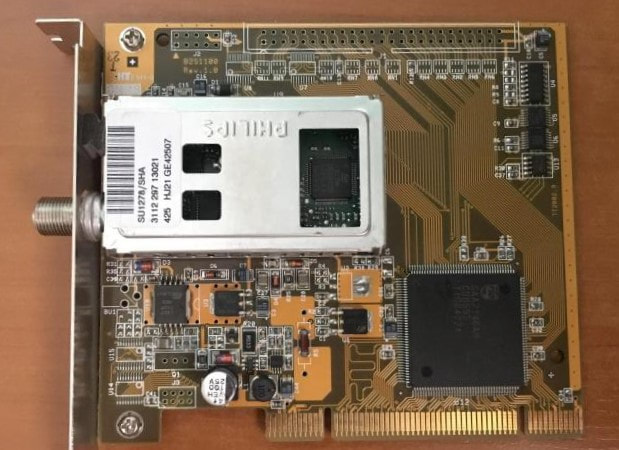
The Philips SU1278/SHA on a typical PCI-card application. Note that the total solution has reduced to the NIM and the Philips SAA7146, the extremely successful MPEG2 decoder/demux.
|
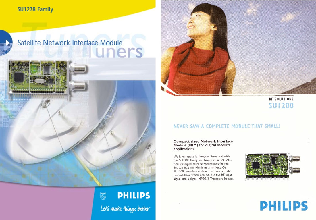
With the departure of president Boonstra the company finally got rid of the "Let's make things better" slogan, still used on the SU1278-Mk1 leaflet on the left. The new company style omitted a slogan, but now made mandatory the use of happy boys and girls, pictured while enjoying - supposedly - the Philips products. All references to application domains, like the satellite dishes, were omitted.
|
The SU1278, introduced in 2001, did reasonably well in the market, given that a NIM was integrally an expensive module in the cost driven satellite market. The advantages were evident, though, and it saw immediate design in on PCI computer cards. However, two trends again put pressure on this product:
|
|
Integration of the ZIF MO and a PLL was the obvious next integration step, and multiple companies were working on it, including Philips Semiconductors with the TDA8260. However, that development ran into serious troubles, essentially due to the conservatism of the BL in Caen which stayed as much as possible in the HS5 bipolar-only node. But such a 16GHz fT node was by now quite outdated, and the design of a 4,5GHz oscillator with such limited frequency margin was really a stretch. In other words, the IC did not meet its specifications, and redesign in Qubic3 (32GHz fT) only started end 2002. Although that eventually turned out to be a good IC it came much too late to the market. In the meantime, a different solution was used, the TUA6100.
The TUA6100 used an interesting concept with two cascaded PLLs. To generate the four quadrature LO signals for the balanced IQ-mixer it uses a VCO2 at four times the required LO frequency, so between 4x950= 3800MHz and 4x2150= 8600MHz. Division by four delivers the four LO phases. This VCO2 is locked to a reference frequency which is the VCO1 frequency of a first PLL. With divider ratios R2 and N2 the relation becomes fVCO2= N2/R2*fVCO1. However, as shown the feedback loop of PLL1 is disconnected, and the output of VCO2 (divided by 4) instead used as the measured oscillator frequency in PLL1. The combined cascaded PLL1-PLL2 loop thus controls VCO2 to the desired frequency: fVCO2/Q2= N1/R1*fref. When stabilized the frequency of VCO1 = R2/N2*fVCO2. Since R2 and N2 can only be 2, 3 or 4, this means that VCO1 can be used in three modes: if R2/N2 is lower than 1 VCO1 will be at a lower frequency, for R2=N2 on the same frequency as VCO2/4 (which is normally an undesired situation, potentially generating beats close to DC) or for R2>N2 VCO1 is higher than VCO2/4. In practice this means that the tuning band is cut in two, with a switch over at 1430MHz since the tuning range of VCO1 is 400-2900MHz. For example, assume R2/N2= 3/2. Then for tuning the LO (VCO2/4) from 950 to 1435 means VCO1 will tune below the LO from 1425 to 2152MHz. For the high band (LO= 1424-2152MHz) R2/N2= 2/3 and VCO1 will be above the LO from 949 to 1434MHz). In this example the minimum distance between VCO1 and the LO is minimally 450MHz, avoiding near-by beats. For different R2/N2 ratios the distance can be increased further. |
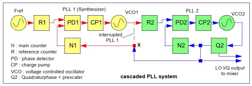
Concept of the Infineon TUA6100 cascaded PLL. Q2 is equal to 4 for generating the LO quadrature phases. With R2/N2 not equal to 1 VCO1 will be either lower or higher than the LO frequency VCO2/4. [Infineon TUA6100 Data Sheet, 2001]
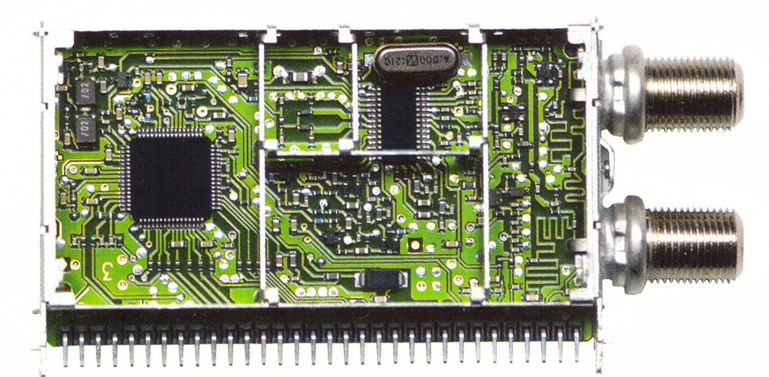
The Philips SU1278/LV-Mk2. Upper right the TUA6100, left the 64-pins STV0299 channel decoder. The loop-through RF transmission line from the top input to the lower output connector is clearly visible. Upper left the two large inductors of the DC/DC-converter are visible.
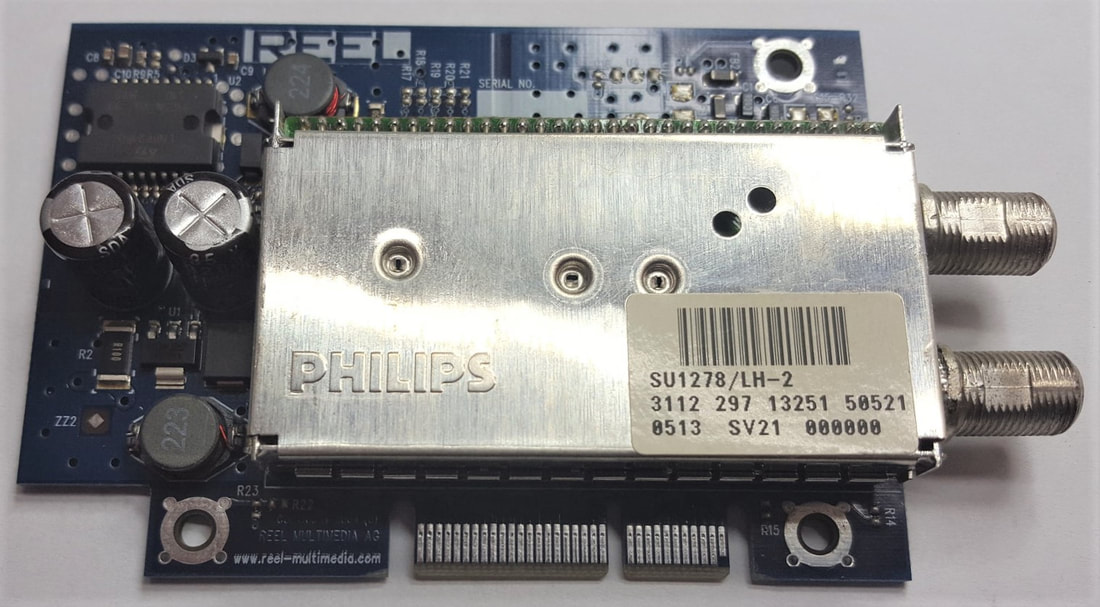
The Philips SU1278/LH-Mk2 on a typical STB insert card, in this case of the Reelbox STB. The SU's were first mounted on a carrier PCB, which was then vertically mounted on the STB mother board.
|
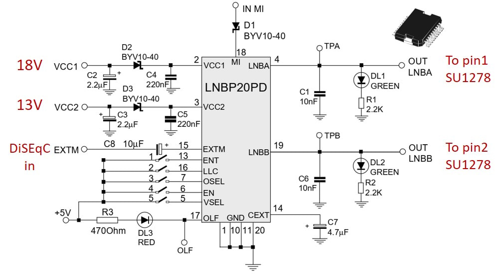
Circuit diagram of the LNBP20PD application, the LNB voltage controller used in the SU1278/P-2. It could se;ect either the 13V or 18V per output, while the EXTM input received the DiSEqC control signal to modulate a 22kHz 1V oscillator, the output of which was added to the DC. [ST Application Note 1230, 2000]
|
A last extension and functional integration of the SU platform was the addition of the LNB control. As explained earlier classical LNB's used two forms of configuration switching: 13/18V supply voltage switching for Vertical/Horizontal polarization selection and a 22kHz tone burst to switch Low/High Band. The new DisEqC standard extended this concept, using pulse modulation of the 22kHz tone. The new channel decoders like the STV0299 did generate the DiSEqC digital control signals, but the LNBs required quite high voltages and currents, and therefore a dedicated voltage generation and control IC. In principle this function had to be provided by the PCI card (on the picture of the SU1278 on the Reelbox PCI card this circuitry is visible in the upper left corner of the main board) but was not the type of digital circuitry preferred by the system designers. On the contrary, this was pure analogue power electronics, and therefore the idea of adding it to the NIM makes sense, thus releasing the board designers from further analogue worries. The function provided was in principle the reference design provided by ST for its LNBP IC, which was the standard IC for this function.
|
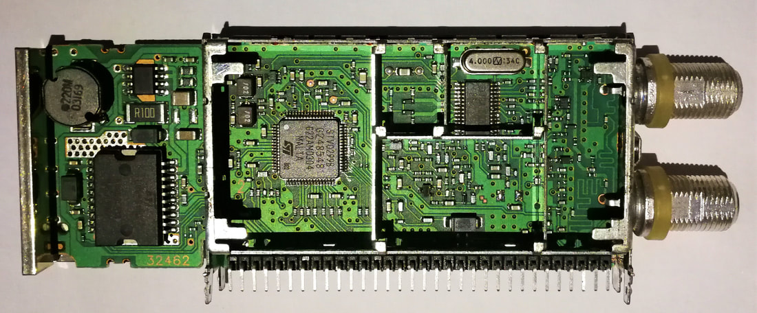
Interior view of the Philips SU1278/LV-2/P-2 with loop-through (L) and on the left the LNB power supply and command controller around the LNBP20P in its Power-SO20 package. The entire external PCB section had an aluminium heat sink attached to it. [Jan van Daal collection]
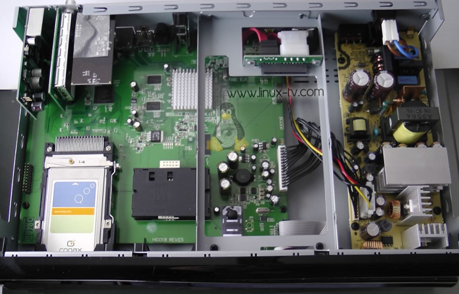
The SU1278 (upper left) in a Dreambox 7020. [Linux-TV.com]
|
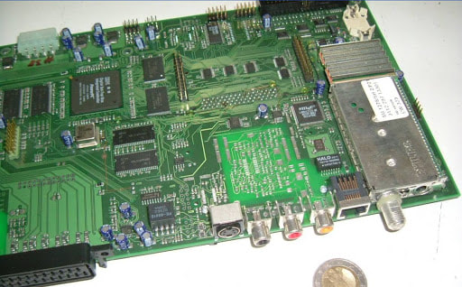
The SU1278/LV-2/P-2 on a STB main board.
|
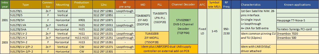
Overview of the Philips SU1278 Satellite NIM family. The first generation was mainly used on PCI-cards, the second in STBs.
SX800 and SX900 economy LNBs, 1998
|
The main challenge of the LNBs was price erosion. As mentioned, there were many competitors, and no supplier had guaranteed supply relations with STB makers. So, in the end it was an open and thus purely price-driven market. Philips, with its high-quality LNBs, could demand a small premium, but not much. Cost reduction was thus the major driver once the functionality was standardized (single, dual, twin, universal Astra, universal twin, quattro, quad). The focus areas for cost reduction were:
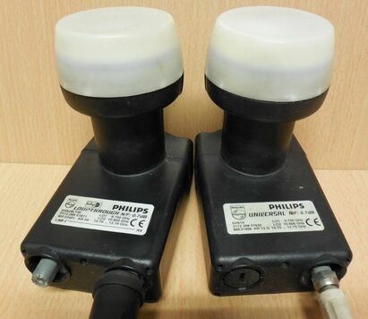
Left a DiSEqC1.1 Philips SC829LT Universal LNB with loop-through, with the right (black) output connected to the input of the right standard SC829 Universal LNB. Both are from the new economy family with plastic outer housing.
The SX800 family was rather limited: an enhanced Astra (2050MHz IF) SX817, a universal triple-band SX819 and a universal with loop-through and DiSEqC 1.1 (uni-directional) or 2.0 (bi-directional) control, the SX829LT. The DiSEqC standard was an invention by the LNB team of the BU Tuners as a method to control systems with (many) more than one LNB. For technical details see the call-out on the right. DiSEqC was enthusiastically accepted by Eutelsat, which struggled to maintain a position next to the very successful Astra and saw this as a method to have LNBs and dishes for their satellites easily added to an existing installation. DiSEqC was launched in 1998, and the BU, as its inventor, of course needed to have a pilot product available. It was duly advertised in the Eutelsat publicity campaign. For quite some years the SX829LT was one of the very few DiSEqC-enabled LNBs in the market. Nevertheless, it sold in limited numbers, simply because it took DiSEqC multiple years to make itself a de facto standard in the satellite market. Astra was obviously not promoting it - why should they? - but couldn't stop it either. If we take Philips Digital Networks as mainstream reference it took five years, until the DSR1010 and DSR2010 in 2002, to see DiSeqC functionality integrated as a standard feature in the satellite STB. Until then the SX829LT would also remain the only DiSEqC LNB within the Philips portfolio.
The next family was the SX900, the first family of co-axial LNBs. In this family a much larger number of technology steps: a much smaller PCB and size, ultra-sonically welded outer housing. Design-wise the main innovation was the introduction of the cold FET arrangement, with the HEMTs biased at 0V Drain-Source voltage, so without bias current. However, the SX900 was mainly used for the less mainstream products, possibly - or because of that - the lower margin products that most urgently required a cost reduction. These were the old standard Astra (SX915, 950-1750MHz IF), Enhanced Astra (SX917, 950-2050MHz), Measat, PanAmsat, Telecom, and US DSS (DirecTV) models. There are hardly traces of this family, and I doubt it sold in large numbers. However, it acted as the carrier for several important technology and cost reduction innovations, which are always easier to introduce in moderate volume products for proper de-risking. As such the SX900 paved the way for the SX700 and SX1000, which were to become the main products for the coming years.
|
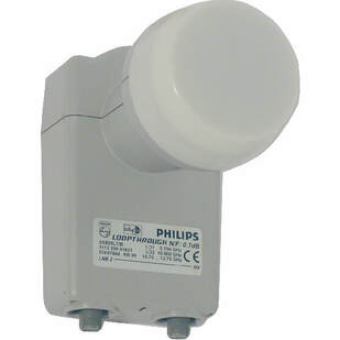
The main runner of the new SX800 family: the SX829LT with loop-through for DiSEqC control. This was the very first DiSEqC compatible LNB in the world.
DiSEqC standard, 1998
Due to the proliferation of Digital Satellite Broadcast during the 1990s outdoor systems became increasingly complex, especially since users installed multiple dishes for receiving from multiple satellites. In general, this then led to large bundles of (expensive) RF coax cables down to the STB, which in turn often had limitations in terms of available input ports. A solution was needed.
This became Digital Satellite Equipment Control (DiSEqC), an invention by the Philips Krefeld LNB design leader Ron Schiltmans, while Peter Burgstaller made the clever proposal to base the protocol on the very successful Philips TV Remote Control RC05 code. DiSEqC was quickly embraced by Eutelsat because they were often secondary to the Astra receiver, and were struggling to get more subscribers. Paid by Eutelsat, Philips Research Labs in Redhill (UK) worked out the protocol and system standard. With DiSEqC RF switches could be series connected over a single cable. The DiSEqC1.0 standard for one-way communication was published in 1997, followed by the 1998 2.0 bi-directional version. 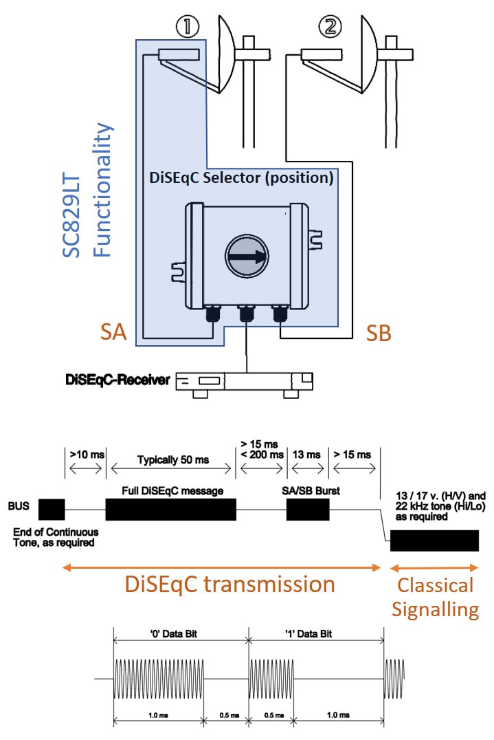
DiSEqC basics. [DiSEqC für Techniker, Klaus Müller, Spaun]
DiSEqC re-used the 22kHz for Hi/Lo band switching in standard LNBs, to transmit instructions first. In a DiSEqC system multiple 1-to-2 or 1-to-4 RF splitters could be cascaded to make a single tree structure for up to 64 LNBs. The path through this tree was programmed using the DiSEqC messages based on a Master-Slave set-up. At the last switch a final Satellite A-Satellite B (SA/SB) burst selected the dish. After that regular 13/18V and 22kHz on/off signals conditioned that LNB. In a loop-through LNB like the SC829LT the last switch was integrated into the LNB.
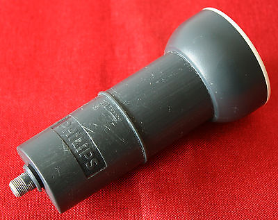
Rare picture of the SX917 enhanced single LNB, the first co-axial LNB of the BU.
|
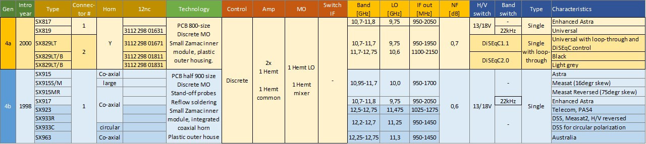
Overview of the Philips SX800 and SX900 families of single LNBs.
SX700 and SX1000, the last Philips LNBs, 2000
The Ku-band LNB developments stabilized around the turn of the century, in the sense that - at least initially - no major functional developments were taking place. LNB functionality had stabilized into four standard types:
- the universal (Astra) single, which could be switched between horizontal/vertical and low/high-band modes
(The universal can be considered as the maximum single LNB functionality; non-Astra system like DSS (DirecTV) and Asian systems mostly had smaller frequency bands, and as products these LNBs were simplified versions of a universal). - the universal twin, with two outputs that could be independently selected to any of the four modes.
- the universal quad, with four independent selectable outputs.
- the quattro, where each output used one of the four modes, such that the full receive band could be sent to SMATV installations.
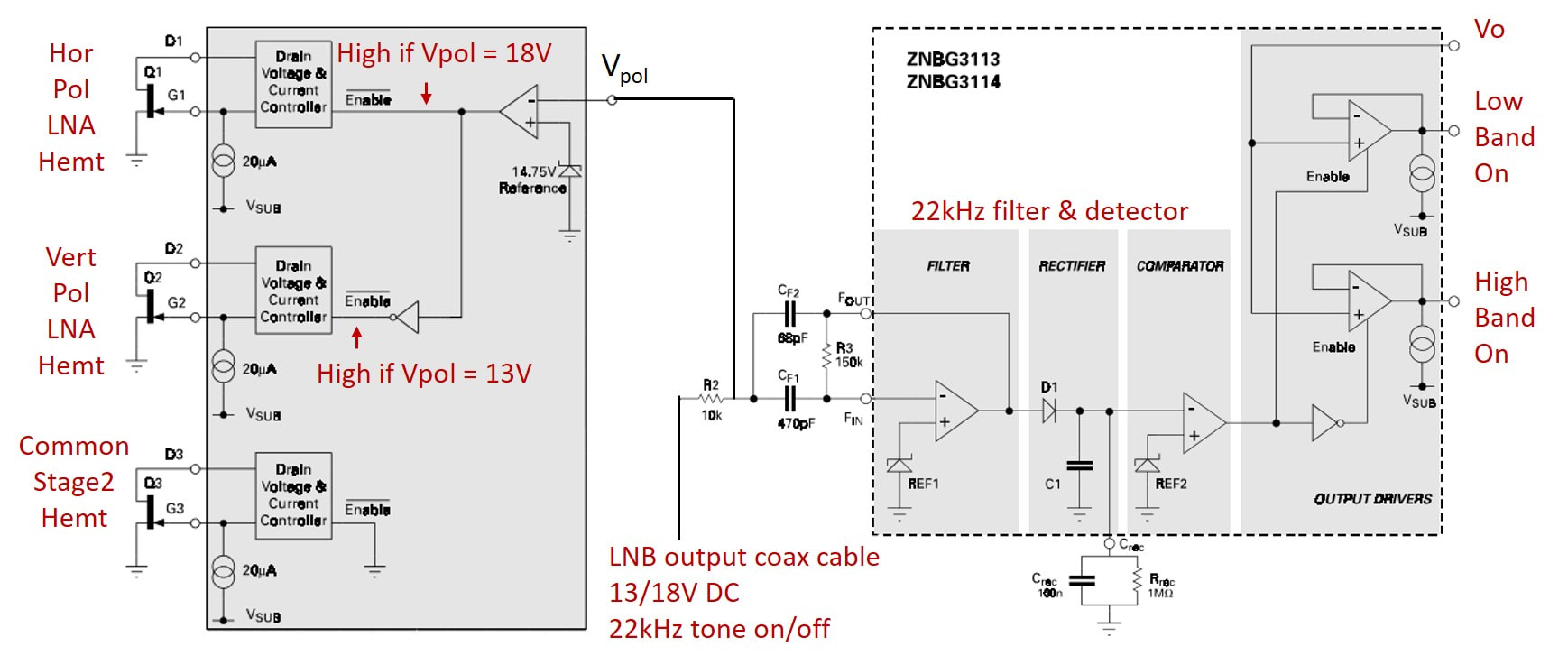
Block diagram of the Zetex ZNBG3113 as used in the SX1019 singles. The ZNB400 four fixed HEMTs was used in the SX700, as well as the ZLNB2012 with dual controllers in the SX900DS and Quad. [Zetex ZNBG3113/14 Application Note, October 1998]
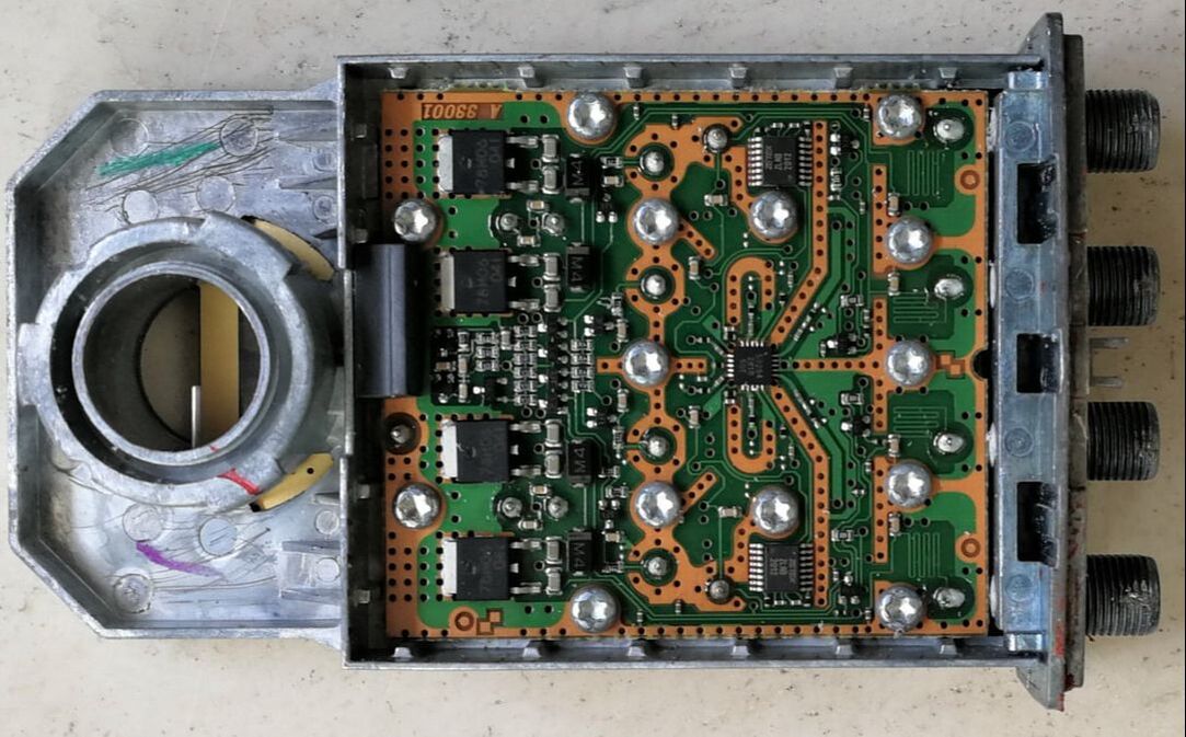
The control print of the Philips SX719QS Quad LNB. From left to right 4 5V voltage regulators, in the centre the 4x4 GaAs switch, above and below that the two Zetex ZLNB2012 bias controllers for the mixer HEMTs, omn the right the connections - both RF and DC - to the four outputs. [via Hans Brunas]
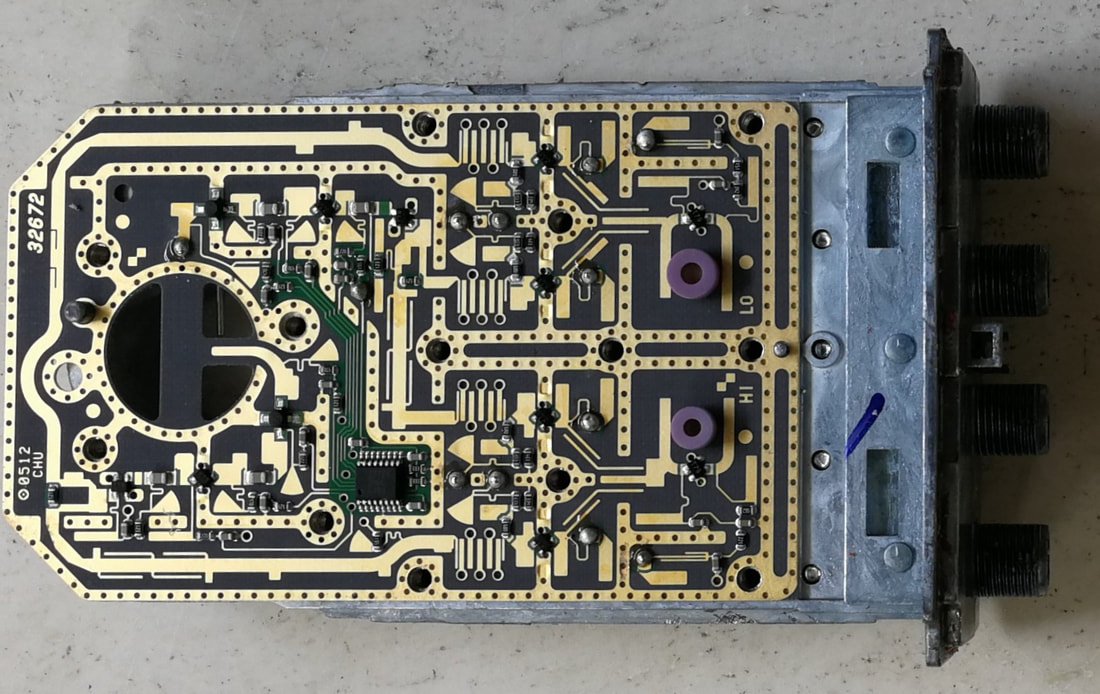
Top view of the RF board of the Philips SX719QS Universal Quad LNB. All different functions mentioned in the text are clearly visible. Note that right of the central mounting holes, so from and including the BPFs, the layout is fully symmetrical except for the LO tuning strip lines. [via Hans Brunas]
|
1. the first new feature was the use of an IC for all bias control. This was from Zetex (a UK company that was a management buy out from Plessey, itself in 2008 acquired by Diodes Inc) and contained circuits to detect the control voltages on the LNB input/output (13/18V for vertical/horizontal and 22kHz for low/high band). It was ideal for the SX1000 architecture with two switched input HEMTs and fixed second stage HEMTs. In the SX700 a different version with fixed HEMT control was used for the input HEMTs, while a dual ZNBG2012 was used for switching the mixer HEMTs.
2. The SX700 substantially simplified the sensitive uWave design by relegating all control circuitry to a separate PCB, which also made it much cheaper. This control PCB was now optimised for each version: Twin, Quad or - with limited functionality - the Quattro. Especially the power components had more space, also for proper heat sinking, while a beautiful symmetrical lay-out resulted. 3. For the output switching fully integrated non-blocking 4x2 (Twin) and 4x4 (Quad) GaAs switch matrix Skyworks MMICs were used, greatly simplifying the matrix design. Because of the drive capability of the GaAs IC only single transistor buffers were needed to the LNB outputs. The RF board showed several innovations: 4. Plastic packaged HEMTs by Mitsubishi, much cheaper than the former ceramic packages. Each H and V branch had two HEMTs, permanently on, and biased by a single Zetex IC. A third amplifier stage used the even cheaper Siemens/ Infineon SIEFET BFP405 bipolar transistor. After power splitting the four branches passed through new and much more compact Band Pass Filters. 5. Compared to the previous SC519Q, which used four GaAs MO ICs, the number of active components was reduced to four HEMT mixers and two oscillators using NEC bipolars. To avoid oscillator pulling the LO signals were split in a passive power splitter. As mentioned, the four mixer HEMTs were biased by the control PCB Zetex ICs. 6. The two RF waveguide probes were no longer co-planar as in the SC519Q. One of the probes was still part of the waveguide, but the other one on a quarter lambda stand-off deeper into the waveguide. This provided much better H/V isolation. |
7. Although the two moulded module covers were classical, they now covered the entire RF board, making the enclosure more reliable. The horn was not integral part of the module and was clicked firmly onto the waveguide. The entire structure was covered by a simple plastic moulded encapsulation using ultra-sonic welding.
|
Because not all cost savings as introduced in the SX700 had been available for the SX900, the SX1019 was the update of the Universal Single LNB with the latest technologies. The main difference with the SX700 was that the input LNA HEMTs were again switched for H or V polarizations, followed by a common second HEMT stage, all three biased by the Zetex ZNBG3113. The mixer HEMT was independently biased, while the oscillators were the same NEC bipolar transistors. The two oscillators for low band and high band were also switched by the Zetex IC. The IF output passed through a uPC2712 MMIC 2,6GHz amplifier and a last buffer stage. The SX1019 used stand-off waveguide probes identical to the SX700. Because power consumption had been reduced so much compared to previous generations , the 5V voltage regulator was now also reduced to a small 3-pin low power regulator.
|
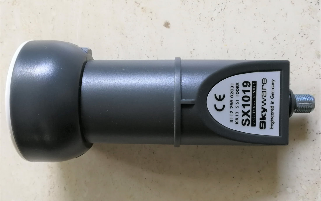
The Philips SX1019 Universal LNB, here pictured when re-branded Skyware. [Hans Brunas]
|
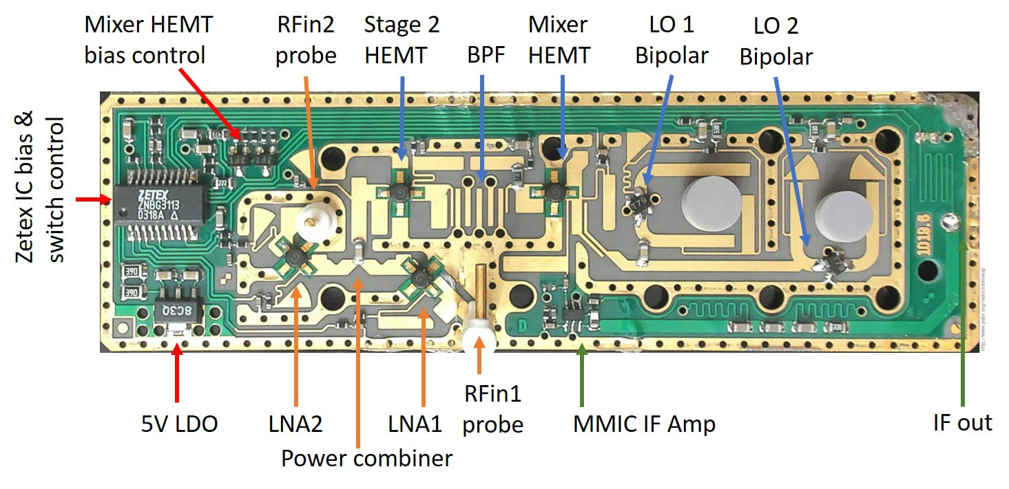
Top view of the Philips SX1019 Universal Single LNB PCB board. All functional blocks and components have been indicated. [Pabr.org]
|
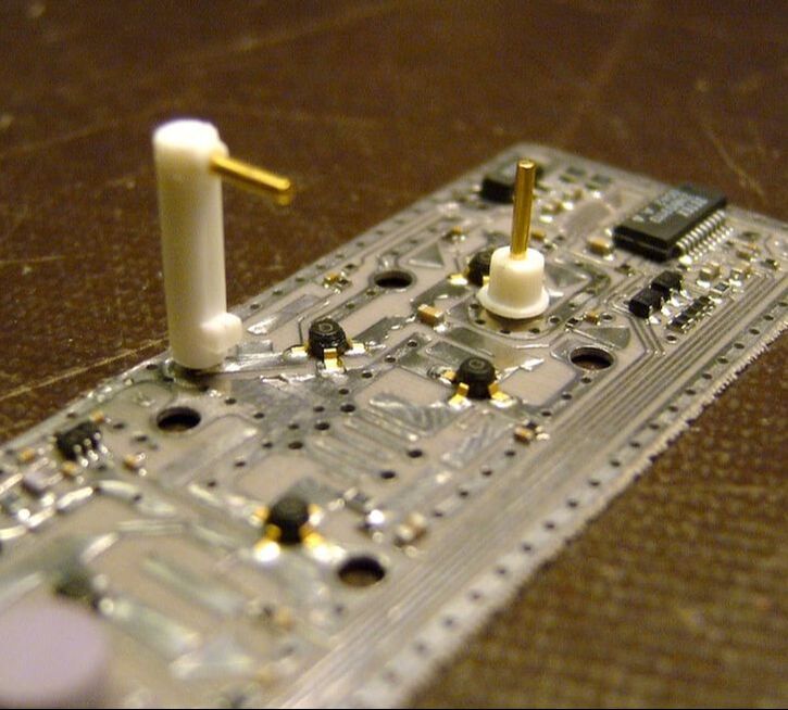
Slanted view of the Philips SX1019 PCB, clearly showing the two waveguide probes. [EEV-blog]
|
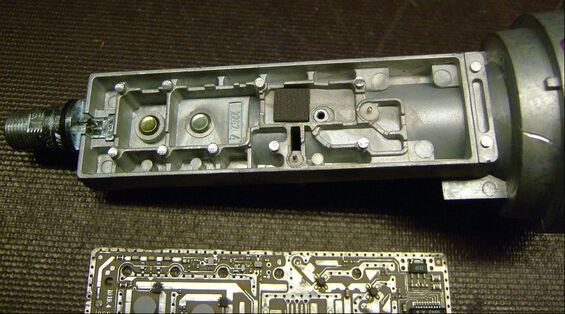
Disassembled Philips SX1019 LNB. The single waveguide plus mounting module is claerly visible, including the two holes for the H and V waveguide probes, as well as the two DRO tuning screws on the left. [EEV-blog]
|
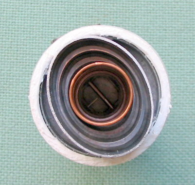
The SX1019S had a modified waveguide for elliptical polarisation. For the reception of circular polarization, a quarter-lambda converter could be inserted into the waveguide.
|
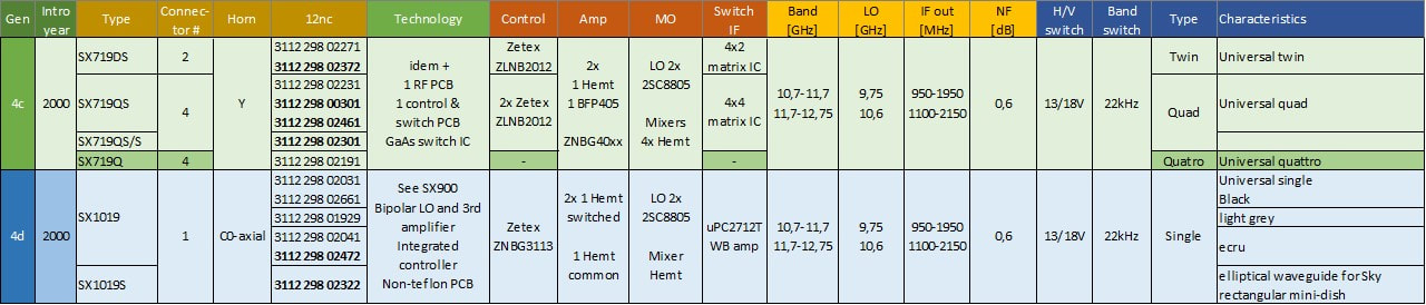
Overview of the Philips SX700 and SX1000 LNBs, the last families developed and initially produced under the Philips brand. Later they were sold under the SkyWare brand name.
LNB business sold to Newtec-Skyware, 2002
The SX1019 marked the realization of the ultimate cost efficient LNB, with the entire P1-P3 production flow fully automated using just two operators per line, one at the start and one at the end. Due to the resulting extremely low labour cost, production could be kept in Europe, and was concentrated in the Krefeld factory. Since all other BU Tuners production had been moved out to Kwidzyn, Batam or Suzhou the entire production floor was now for LNB (which used only half of it). Nevertheless, however efficient the production, sales were not going well because the European LNB market was saturated, flooded by cheap and lousy Asian LNBs. On top of that the bursting internet bubble meant that LNB sales declined from 12Mio€ in 2000 to 8Mio€ in 2001, quite the opposite of the planned 22Mio€ for that year. This meant that the LNB microwave was one of the first on the list of PD Components businesses to be made ready for sale. For LNB this was announced on June 1st, 2001, and rather quickly a candidate buyer was found: the company Newtec from St Niklaas, Belgium, active in larger satellite equipment. They were especially impressed by the microwave volume manufacturing capabilities of Krefeld, and by March 2002 the LNB business was acquired for an unknown amount. The entire business was concentrated in Krefeld, with Development (20 people), Support (15) and Operations (60).
|
Because the LNB business was quite different from the other Newtec products it became a stand-alone subsidiary, selling the products under the brand name Skyware. Newtec had obtained the right to use the Philips brand name for another 2 years, but relatively soon started to promote the Skyware brand. At the time of the take-over the SX700 and SX1000 were the main products in the portfolio, with possibly an occasional SX829LT as the only DiSEqC product. Product names did not change, only the company label.
|
|
|
Part of the new business strategy was the move away from standard Ku-band LNBs. Cheap competition, the resulting low margins, the lack of innovation options - the basic LNB functions remained as they were - and the lack of market growth meant that this was an increasingly unattractive segment. Already in the last Philips days the team had been moving away from standard reception to VSAT, Very Small Aperture Terminals. These are bi-directional satellite ground stations for telephone and internet traffic. They were initially developed for oil rigs and big vessels, but around this time also came available for use in remote areas with no fixed internet access. A Ku-band VSAT system typically used 3m antenna dishes, Ka-band (20GHz) can do with around 1 meter dishes. For reception the same architecture as a good (Philips-style) LNB could be used, next to an upstream channel. In the years after the spin-out Skyware would thus work on the following developments based on its Philips technology inheritance:
|
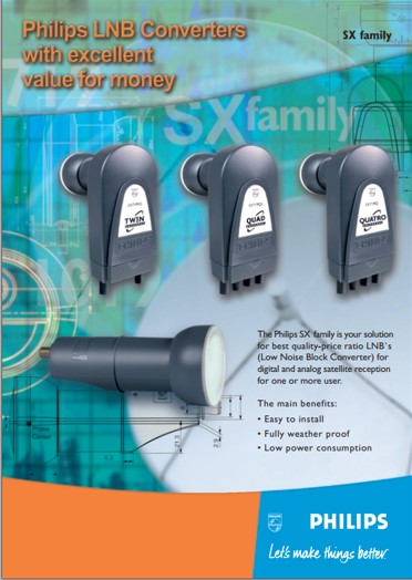
The last Philips LNB product leaflet for the SX700 and SX1000 families. [Philips Components, 2000]
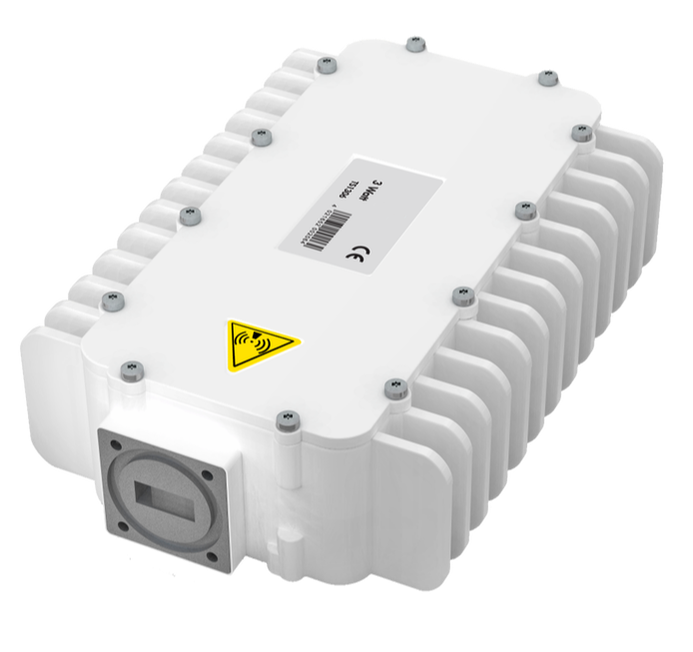
A Skyware VSAT module, the TS1306 Receiver. It was used in conjunction with the TV1106 transmitter.
|
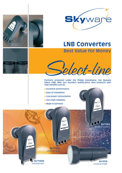
The same product leaflet from Skyware, including explanation of the production facilities in Krefeld. [Skyware, 2002]
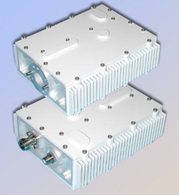
Two more Skyware VSAT modules.
|
But Skyware, apart from the IC relation with Semiconductors, quickly disappeared from the Philips environment. In 2004 production was moved out of Krefeld to China, reducing the Krefeld population to a skeleton development crew. In 2007 Newtec sold Skyware to the US company Andrew from Chicago, and subsequently all LNB activities were stopped, concentrating on VSAT only. In 2009 Andrew merged with ComScope, and now all satellite activities were stopped. These were set apart in a subsidiary Andrews Signal Corp, which was then bought by an investment company. Headquarters and production had by now been moved to the Philippines, with four people left in Krefeld. It then faded into the unknown. The microwave activities of Philips Tuners had been an interesting, remarkable, and technically extremely innovative business, with especially towards the turn of the century the best consumer LNBs in the world in terms of performance and quality. Unfortunately, it had been, almost from the start, an up-hill battle in a company that was quickly loosing all interest in these type of technically complex products.
LNB microwave ICs, 2005-2013
Although the microwave modules businesses of Philips were both sold (Tuners Krefeld) or closed (MMRadiolink, Hazel Grove, Manchester) one related activity survived: microwave ICs. This development started in Philips Research, the NatLab group Integrated Transceivers in Eindhoven, when the latest QuBIC4 BiCMOS technology came available. Although this technology only provided a modest fT improvement compared to QuBIC3 (from 32 to 40GHz), the much improved parasitics (through deep trench isolation) and passive components allowed the start of microwave design. By 2002 it was succeeded by QuBIC4G, the first SiGe BiCMOS node that pushed the fT to 60GHz. In discussions between Research and the Krefeld LNB team it was agreed that the objective function was a fully integrated Ku-band (10-12GHz) mixer-oscillator: the Fully Integrated Mixer-Oscillator Down-converter (FIMOD).
|
Around 2003 the Research prototypes were stable enough for transfer to the business, which was the RF business in Nijmegen, the same BL that developed the tuner Varicaps and MOSFETs. (It regularly changed names, but was known as PL RF Consumer, BL RF Small Signal and lately as BL RF Advanced Antenna Solutions). Product development required a final change to QuBIC4G, functional freeze, and of course adding reliability analysis. The first product, the TFF1000, was released end of 2005. It was an MO down-converter covering the 10,7-12,75 Universal Astra Ku-band with 42dB conversion gain and an integrated phase noise of less than 2,5degr RMS. Newtec-Skyware in Krefeld was of course the first to evaluate, building prototypes of the SX1219 universal single LNB. Both the gain and the 350mW power consumption were considered acceptable for a first product, but on the high side.
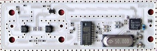
The Skyware SX1219 Universal Astra LNB board. From right to left the TFF1004 MO, the 50MHz crystal, the Philips UBA3000 IC that takes care of the power supply, HEMT biasing and switching and band switching decoding. On the left the two input HEMTs and above them the single bipolar 2nd amplifier. The PCB size is roughly 60% of the previous SX1019.
QuBIC4 BiCMOS technology
QuBIC BiCMOS technology remained the workhorse for all Philips RF applications. In the year 2001 QuBIC4 was released, primarily driven by the then booming mobile phone application. Lower voltages and especially lower power were the main drivers, although differentiating RF performance remained very important. (Therefore, Ericsson Mobile Radio had all its RF ICs developed in QuBIC in a joint design activity with Philips Semiconductors). QuBIC4 introduced the double-poly bipolar transistor with a fT of nearly 40GHZ at a 2,7V supply voltage. The CMOS basis for QuBIC4 became the 0,25 micron C50 CMOS node, allowing considerably higher levels of digital control integration.
Two features of the new QuBIC4 technologies: the double-poly bipolar transistor architecture (left), reducing the losses in the base current path, reducing the base series resistance, and thus improving the transistor noise performance. Deep Trench Isolation (DTI), on the right, reduces stray parasitic capacitances through the substrate, thus improving the bandwidth. [NXP in the making, 2010]
Right at the time that QuBIC4 was launched the SiGe hype emerged, which stated that RF technology not using Germanium in its base was not good. Although the direct benefit of SiGe was still marginal, also Philips could not afford not having a SiGe technology, which became QuBIC4G. Evil tongues suggested it only used a "homeopathic dilution" of Ge, but it did provide some real fT improvement. A more practical upgrade of QuBIC4 was QuBIC4+, essentially the completion of the technology with the wish list items that, under time-to-market pressure, were not yet implemented in QuBIC4. These were mainly the Deep Trech Isolation (DTI), a high quality Thin Film Resistor (TFR) and (in QuBIC4+Dual Gate) a second 5,5V gate oxide for easier I/O design. The latter would become the core technology for future Si Tuner ICs, while all mobile phone ICs used QuBIC4+.
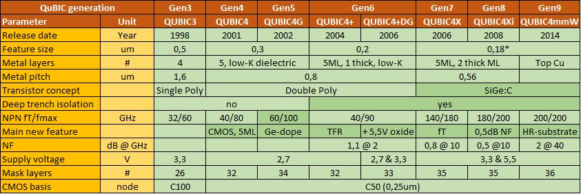
The last additions to the QuBIC4 family were the real microwave nodes. Research had developed a substantially improved transistor using the addition of carbon to the double-poly concept: SiGe:C. My first action after joing Semiconductors in 2003 was to get the development project for what was called QuBIC4X accepted, based on the business case for LNB FIMOD ICs. It was released in 2006 and delivered a spectacular more than 2x improvement of fT compared with QuBIC4G: from 60 to 140GHz! QuBIC4X turned out to be a very successful technology, with later upgrades to 4Xi and 4mmW, mainly on the parasitic structures around the core transistor for Noise Figure improvement.
Throughout the generations of QuBIC, the Nijmegen RF Consumer BL has always been making bipolar-only drop-outs for discrete RF transistors (e.g. the BFP and BFU families), making them a leading player in this domain. QuBIC technologies have made a long journey through the Philips Semiconductors and later NXP fabs: started in Albuquerque (New Mexico, USA) it moved to East Fishkill (New York), then Nijmegen ICN8 (Netherlands) and finally SSMC (Singapore). |
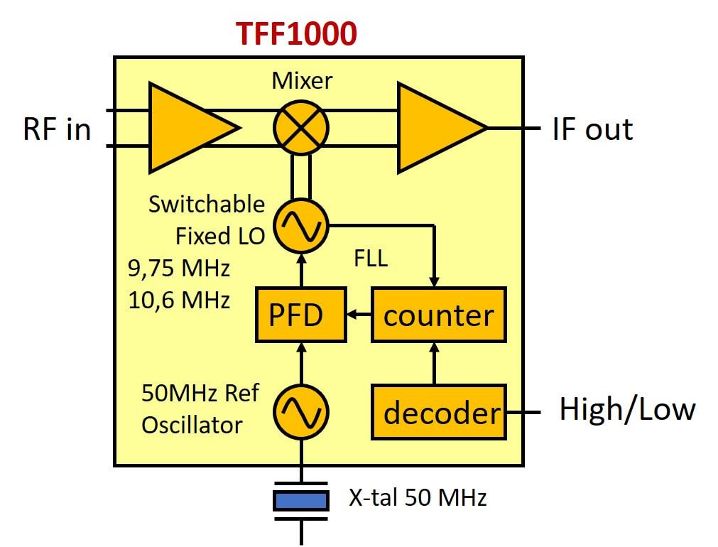
Block diagram of the first Philips LNB microwave IC, the TFF1000.
It therefore effectively took another round of product design before the first real product was launched: the TFF1004, with reduced power consumption (95mA) and gain (9dB less, so 33dB). This one was used in the SX1219 product from 2008. However, like so many first integration steps, also the FIMOD had a serious replacement value issue. When FIMOD developments started around 2000 expensive GaAs MO-ICs were still in use, but in the meantime on standard LNB's both the LO and mixer were discrete, often a mix of bipolar transistors and one HEMT. This made massive deployment of FIMOD ICs problematic, at least for a while. The real volume, due to a much improved price-performance balance, would come with the 2011 TFF1014 family, using the QuBIC4X microwave BiCMOS technology. Using this new technology the TFF1014 had 50% lower power consumption and included I2C control.
In parallel the BL turned to the VSAT application, with lower volumes but much higher value and prices. The first products were the TFF1003 and TFF1007 LO generators, providing the PLL-based LO generation for the upstream VSAT Ku signal at 13,5GHz. In parallel a whole family of TFF11XXY LO generators were launched for general purpose microwave application (XX.Y was the centre frequency in GHz). 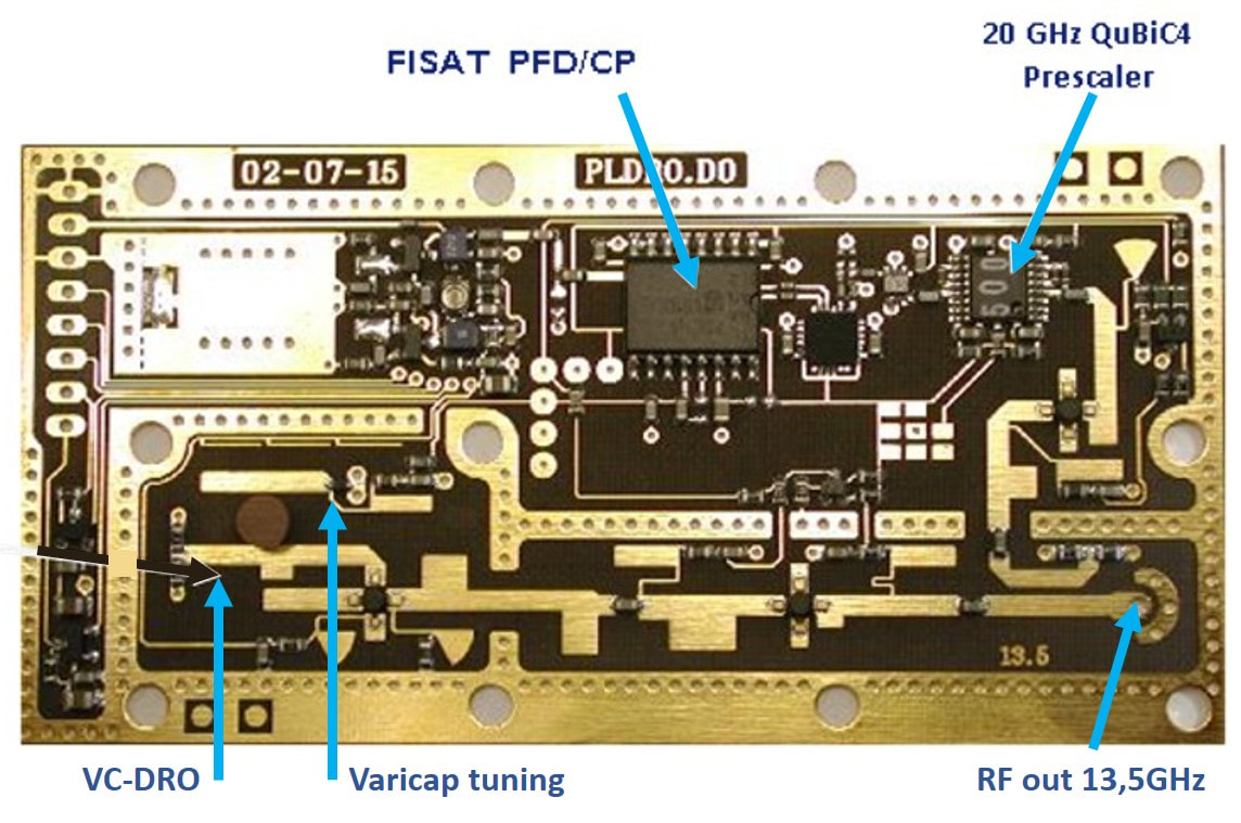
First joint trials by Research and BU Tuners on a 13,5GHz VSAT PLL LO generator, using first samples of a 20GHz pre-scaler. This test board is dated July 2002.
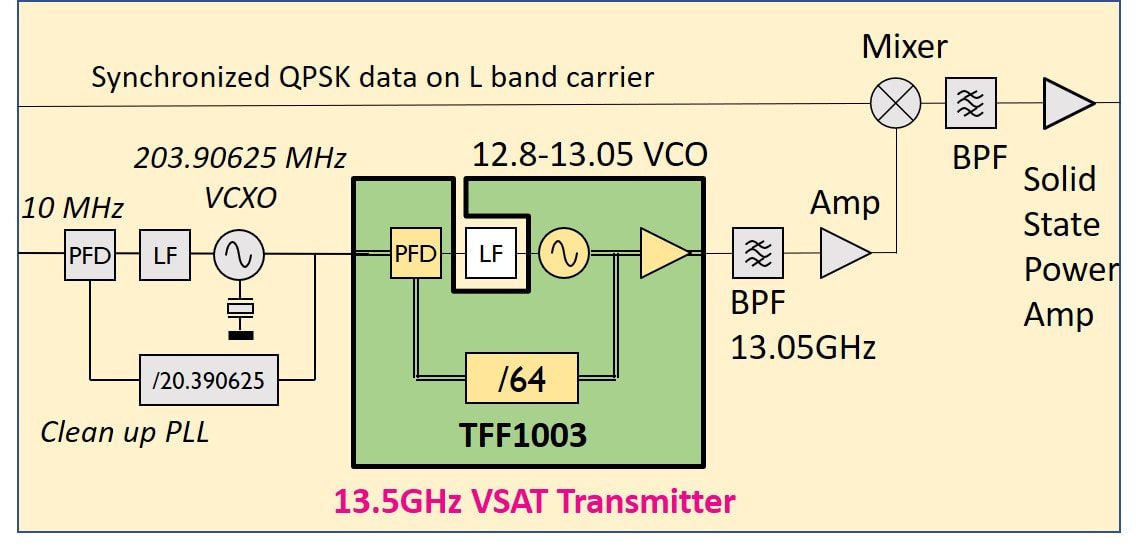
The practical VSAT upstream solution as used by Skyware: the 10MHz reference signal comes from the satellite down-stream, and is used to generate a 203,9MHz reference signal for the TFF1003 PLL, which multiplies it by 64 to 13,05GHz. The TFF1007 used a slightly different input to generate 14,75GHz.
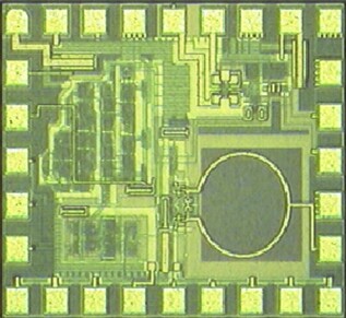
Die photograph of the TFF1003 LO generator IC in QuBIC4X BiCMOS technology. It measures 1 by 0,9mm. The circular track lower right is the LO tank circuit inductor.
The TFF1004 in its HVQFN24 leadless package with exposed ground plane.
|
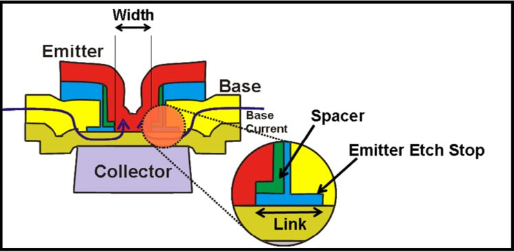
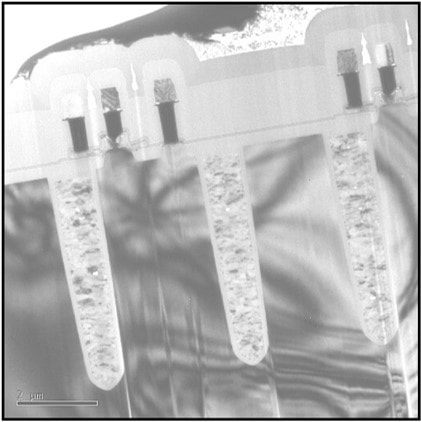
When the successor QuBIC4Xi technology was released early 2011, based on the success with the first generation QuBIC4X TFF1000 family a next generation FIMOD was ready by 2013: the TFF1024 VSAT professional FIMOD and the TFF1044 quad down-converter for Ku-band. The TFF1044 contained 2 LOs and four receive paths, including a full IF 4x4 switching matrix.
So, where Philips sold its microwave module activity in 2002, based on the continued good relation between Philips Semiconductors Nijmegen and the Krefeld Skyware team, a very successful family of LNB and VSAT microwave ICs was developed and produced for more than a decade later. As we will see further down, by 2014 this was effectively the only business remaining with a historical link to the former tuner businesses.
So, where Philips sold its microwave module activity in 2002, based on the continued good relation between Philips Semiconductors Nijmegen and the Krefeld Skyware team, a very successful family of LNB and VSAT microwave ICs was developed and produced for more than a decade later. As we will see further down, by 2014 this was effectively the only business remaining with a historical link to the former tuner businesses.
SDM1700 and SD1800, the last satellite frontends, 2004
Satellite was the RF domain most impacted by silicon integration. Because of the much more predictable RF environment (after the LNB a low dynamic range input signal, no in-band interferers) designing satellite RF ICs was in principle easier than for terrestrial reception, assuming one has a sufficiently high-frequency IC technology. As we've seen, the initial efforts to integrate a Zero-IF (ZIF) satellite frontend in the HS5 bipolar technology (the TDA8260) essentially failed, simply because the phase noise performance was not good enough. However, with the QuBIC3 32GHz BiCMOS technology it should be possible to provide full satellite RF integration. (Although at this time QuBIC4 double-poly technology was also available, the conservative BL in Caen considered that too expensive, and preferred QuBIC3).
|
In the section on the SU1200 NIM, Philips Semiconductors had been trying too long to push the TDA8060 ZIF-MO and was therefore late with the ZIF MOPLL, such that the the BL Tuners used the Infineon TUA6100; good but always too expensive. Because the TDA8262 was late, for the next product the BU therefore used the TDA8261, still in HS5 but now meeting specs and much cheaper because the BL in Caen wanted to push out the Infineon IC. The real threat came from ST Microelectronics, leader in the satellite segment, which announced for 2004 the full integration of the RF and channel decoder in one IC, the STV0399.
|
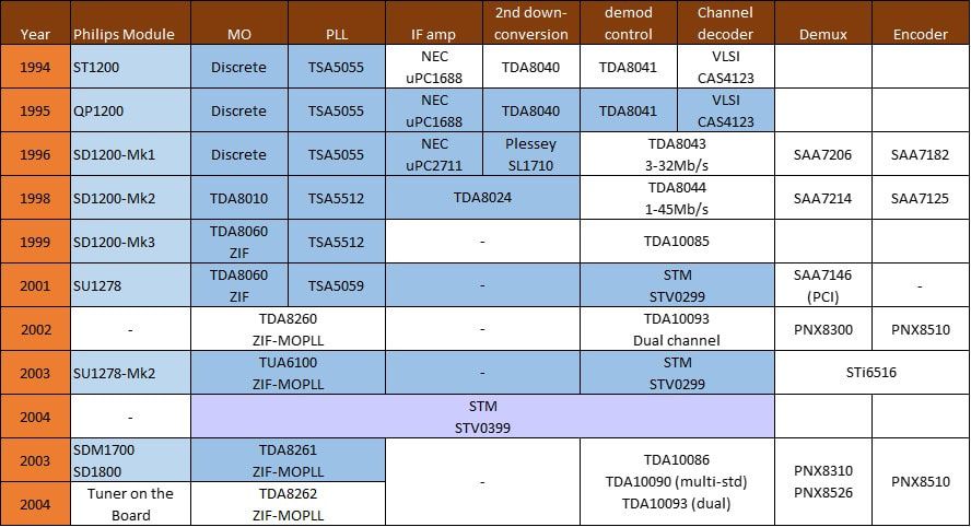
The functional integration of the satellite front end receiver function over the different Philips product generations. The darker blue boxes illustrate the ICs actually included in the products.
|
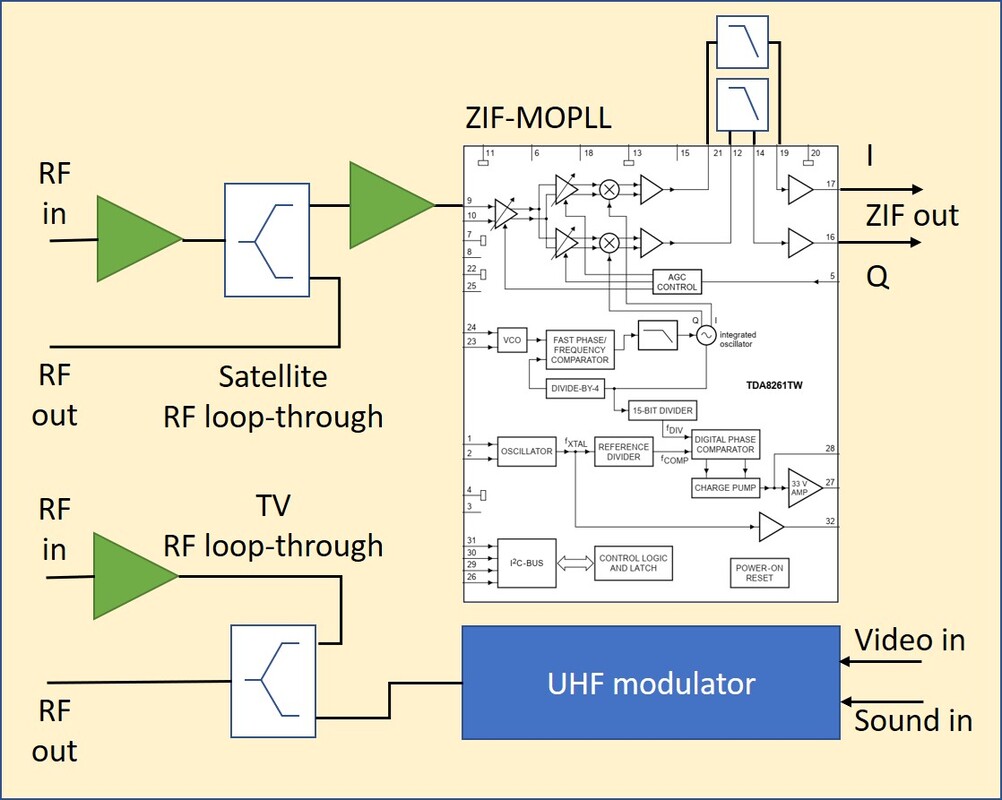
Block diagram of the Philips SD1700 satellite front end with loop-through and cable re-modulator.
Whether the BL liked it or not, the cable re-modulator was probably not in high demand, the market required pure satellite receivers, with or without loop-through. With one or two connectors it became a standard module again, fit for horizontal placement on main boards. This was the SD1800, which became the last ever satellite front end made by Philips. It used the same frame as the SDM1700, but now also horizontally mounted and with two regular side connectors. The SD1800 seems to have been used mainly on PCI cards.
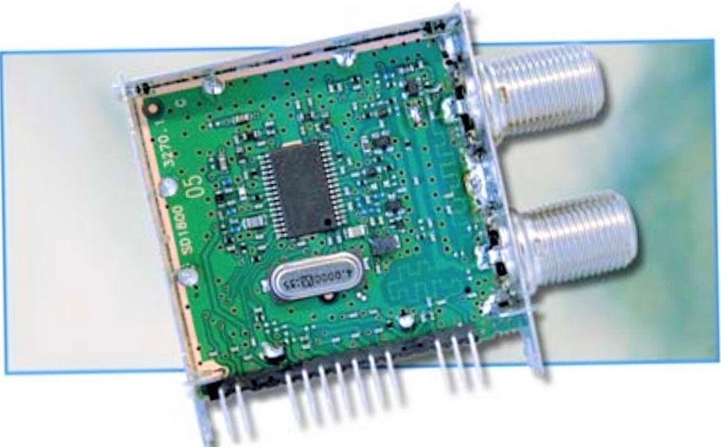
The Philips SD1878 satellite front end, essentially the SDM1700 without cable loop-through and re-modulator. It contained a single TDA8261 ZIF-MOPLL IC.
|
The challenge for Tuners was that the added value of a module with a fully integrated tuner inside was very limited. The product that was based on the improved TDA8261 ZIF-MOPLL, still using HS5, therefore tried to maximize the value by integrating as many functions around the MOPLL as possible:
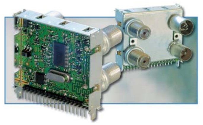
The Philips SDM1700 satellite front end. [Philips RF Solutions product leaflet, 2004]
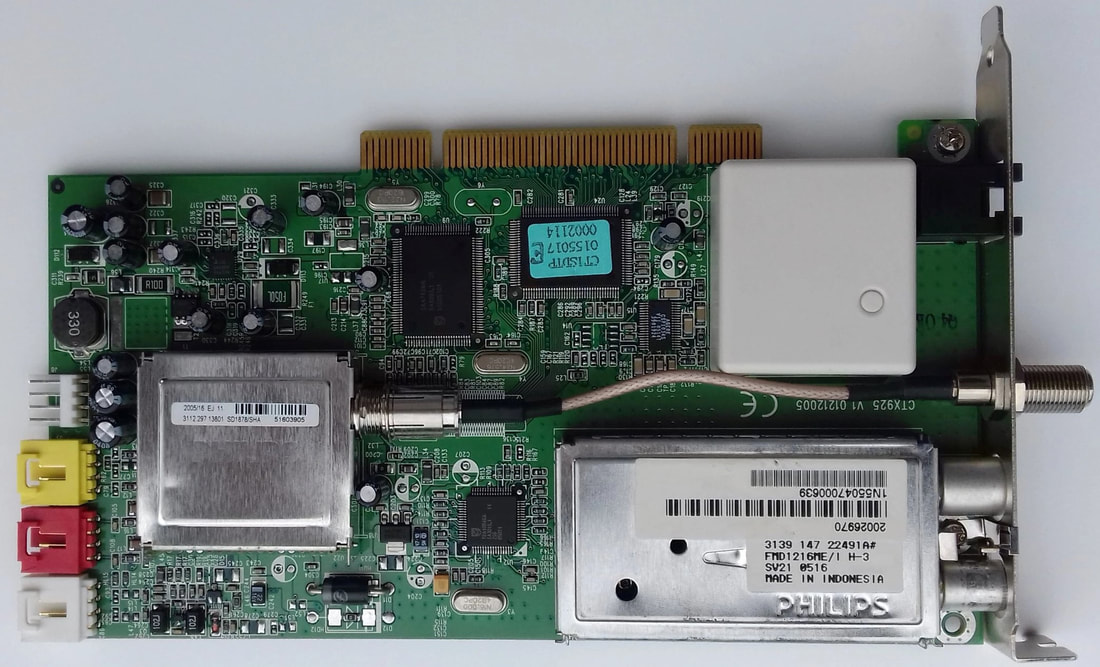
The SD1878/SHA satellite fron tend on a Creatix CTX625 combo terrestrial-satellite PCI card. For hybrid analogue and DVB-T off-air reception it used the FMD1216ME/IH-Mk3.
|
As mentioned in the introduction, satellite front end functionality was coming to the point that RF modules were no longer required. The dream of the BL TV Frontend of "Tuner on the Board" had become reality. This was finally achieved with the TDA8262, the first QuBIC3 satellite IC, that integrated a low-noise LNA with 55dB gain control, an RF loop-through, the programmable 5th order ZIF low-pass filters, and a fully integrated local oscillator in combination with a new PLL that used a 16MHz crystal reference. The TDA8262 could be used in either Master or Slave mode for multi-tuner applications. The BL in Caen, like its competitors, aggressively pushed the Tuner-on-Board concept, which was broadly accepted. It meant the end of the satellite front end product line of the Tuner group, which had started in 1987 with the CB112 and had typically delivered some 10% of the BU sales. Caen continued the satellite IC line quite successfully for another few years at a 15-20Mio$ sales level. With that the satellite products within this Tuner History end.
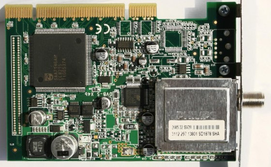
The last known application of a Philips SD1878/SHA satellite front end: a Divimedia TV-Star PCI card. The large IC on the left is a Philips SAA7146 PCI interface.
|
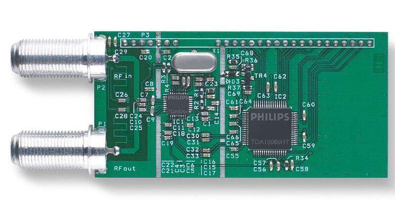
A Philips Semiconductors reference design of a TDA8262 ZIF-MOPLL and TDA10086 satellite DVB-S channel decoder. Note that the form factor is very similar to an equivalent SU1200 NIM.
|
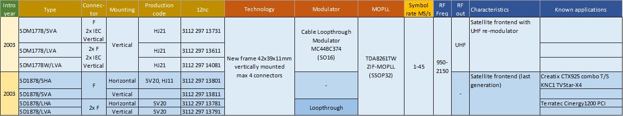
Overview of the last families of Philips satellite front ends, the SDM1700 and SD1800. Note that the SDM1700 was produced in Kwidzyn (HJ21 production code) while the SD1800 was produced in Singapore (SV20) after initial trial runs in Kwidzyn (HJ11).
FQ1200-Mk3 multimedia frontends, continuing success, 2002
|
With the FM1200-Mk2 introduction in 1997, offering not only TV but also FM radio reception with a single module, Philips had re-established itself as the undisputed leader in the PC Multimedia frontend segment. With this family volumes steadily grew to 3,5 Mio modules by the year 2000. There were only two issues that hampered further growth: the RF immunity problems with ATI and competition obtaining the FM ICs too. The RF immunity issue, caused by small holes in the frame, called "encasing slots", near the connectors, and meant to fix the PCB to allow proper re-flow soldering, was solved by wrapping the module front by conductive tape and soldering it around the connector. This cost the BU around 1,20USD on a sales price of on average 10 USD. Fortunately, this was only required for ATI, one of the biggest customers. It was obvious that a new frame design was required with much higher ingress immunity, which became the FM1200-Mk3. Because of the eternal pressure on size reduction, it was therefore combined with a shortening of the frame, from 89 to 70mm. Other significant technology changes were that all ICs now became SSOP, with the IF-IC at the (bottom) A-side and the MOPLL at the (top) B-side. The Mk3 also introduced - after quite some process headaches - lead-free soldering, while the metal frame and cover received an additional tin plating to prevent rusting. And finally, the two separate pin blocks of the Mk2 became one, solving some nasty mechanical application problems with not-perfectly aligned pin rows.
|
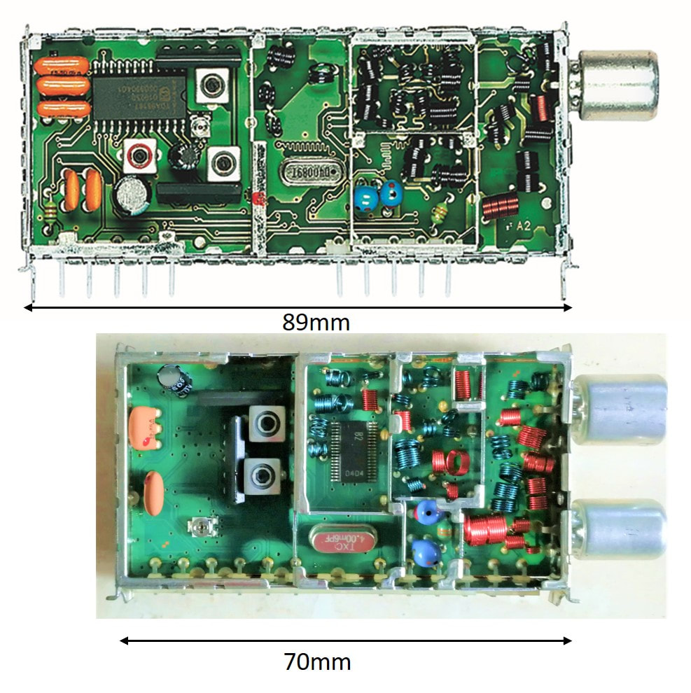
Size and technology comparison between the FQ1216ME-Mk2 (top) and FM1216ME-Mk3 (bottom). [via Darko Jancin and Ite Weide]
|
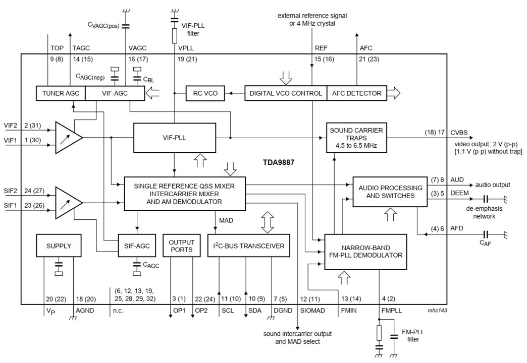
Block diagram of the Philips Semiconductors TDA9987 AFRIC. The broad arrows indicate that almost all functions were I2C programmable, no external adjustments for mode selection were required. [Philips TDA9887 Data Sheet, October 2003]
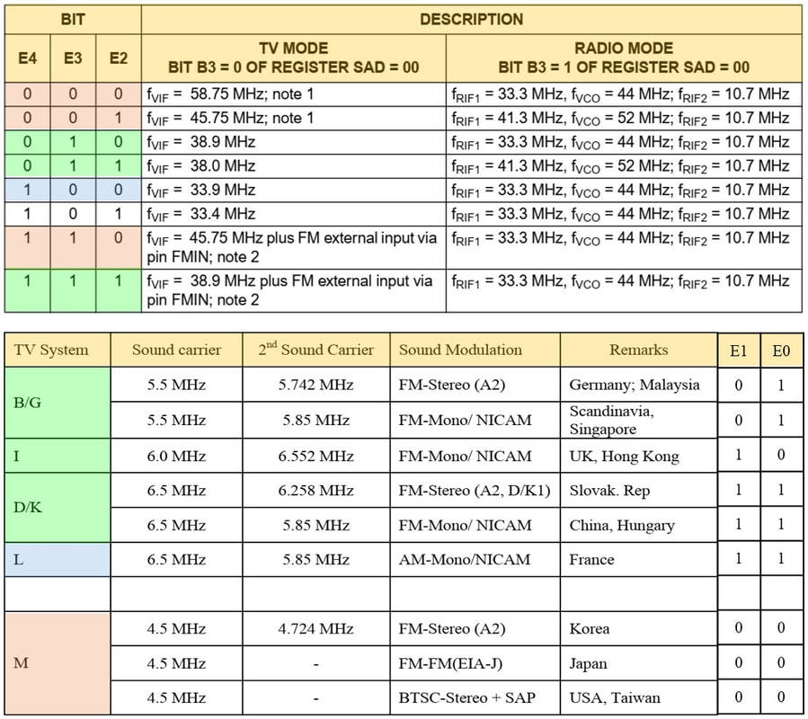
By the year 2000 the world of analogue TV reception was still a zoo of standards. The TDA9887 could demodulate them all, using 5 I2C bits to code for them. The lower table shows the sound system selection using bits E1-E0, the upper table the same for video using E4-E3-E2. Identical colours refer to the same group of standards. [TDA9887 Data Sheet and FM1236 Application Note]
|
The biggest political issue, and a further proof of the declining internal co-operation within the company, was the IF IC. Traditionally there were yearly roadmap and program alignment meetings between the Hamburg IF IC development group and the BU Tuners. From these discussions the Tuner group only knew the TDA9818 QSS-IC, which was used in the FQ1216ME and introduced as last version of the 1200-Mk2 family. The initial PRS document assumed the same IC for the 1200-Mk3. It was therefore a major shock when Alps introduced an entirely new Philips (!) IF-IC, the existence of which was unknown to the BU. On top of that it was a highly advanced Alignment FRee IF IC (AFRIC), substantially simplifying the IF design. In the years before, Philips Semiconductors had already sold the TDA9809 FM-radio IC to all Philips competitors (Temic, Samsung, LG, TCL) which all offered copies of the FM1200, and because their quality was less all at lower prices. So halfway the architecture and project definition the FQ1200-Mk3 had to be redefined towards the TDA9887 family.
But whatever the politics around it, the TDA9887 AFRIC was a great IC, the culmination of the IF expertise in Hamburg. On the one hand it was fully programmable as shown in the tables left, covering all known TV standards. All this was done and controlled internally, without the need for any external alignment or adjustment. Furthermore, all bulky sound trap filters (in a Multi Europe version three were required) could be deleted because the IC had an internal programmable sound trap. The application of the IC thus became very easy: a handful of discrete components, a video and sound IF SAW filter (both smaller size SIP5D versus the Mk2 SIP5K) and for FM reception a 10,7MHz filter. Interestingly, the TDA9887 had the ability to convert the FM radio through the VIF input, requiring that the FM channel was converted by the tuner to an IF (for most standards) of 33,3MHz. In the mixer it was then mixed with 44MHz fixed VCO to 10,7MHz and fed to the FM demodulator. However, the BU did not use this option, because of Cenelec 55020 requirements, SNR, and phase noise. In addition, to fulfil the CE55020 for Europe, the 10.7 MHz signal needed additional selectivity for adjacent channel suppression. The FM radio channel was therefore down-converted in one step to 10,7MHz, as in the Mk2 family, and, after proper filtering, fed to the FM-IN port of the IC. |
The AFRIC was used in three versions: the TDA9985 (negative video modulation and FM sound only), TDA9986 (additionally SECAM positive video and AM sound for France) and the TDA9887 (negative and positive video, FM/AM sound plus FM radio). They provided the ultimate analogue IF integration, and no next generations of stand-alone IF-IC would follow.
|
The second main component of the FQ1200-Mk3 was the MOPLL, the first time in a Multimedia frontend. It as been explained earlier that the BU, in order to get price pressure on Semiconductors TUN2000 MOPLL, had requested a copy from Siemens (since 1999 Infineon), the TUN2010. This IC had been introduced in some of the UV1300-Mk3 models, but these quantities were insufficient to reach the committed 4Mio pieces per year. It was therefore decided that the FQ1200-Mk3 had to use the TUN2010. All in all, this required a complete re-design of both the PAL and NTSC tuners: MOPLL introduction, IC on B-side, and less space (from 50 down to 40mm length). The tuner section also used the new BF1200 MOSFETs, using the twin BF1204 for VHF, introduced in the UV1300-Mk3.
|
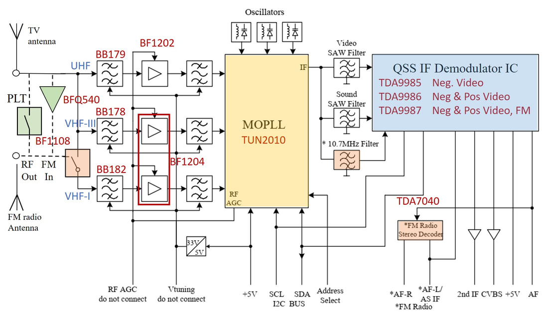
Block diagram of the Philips FQ1200-Mk3 multi-media frontend family. The two main functional options were FM-radio (with additional orange blocks) or alternatively an active broadband loop-through amplifier or passive loop-through (green). All these features used the second RF connector.
|
|
Compared to the 1200-Mk2 family the core diversity of the Mk3 was substantially reduced. The first basic model was the FQ1236 for NTSC, introducing much improved sound quality compared to the intercarier FI1236-Mk2. Interestingly, this model was mainly used in US (LCD)-TV applications in the form of bolt-on boards much the way Philips was for digital TV. The slightly modified FQ1286 (58,75MHz VIF) was probably the first successful Tuners product ever in Japan and used on Japanese PCI-card makers like SK-Net's Monster TV. The US PCI market, in contrast, mainly used the FM1236 with radio function, where ATI's All-in-Wonder 9600 and 9700 families were main runners, next to AverMedia and Asus. To speed up the introduction of the smaller Mk3 for ATI, while the TDA9985 release was delaying, a unique intercarrier product was launched as one of the very first Mk3 products: the FI1236/WH-Mk3, where the W indicated the use of an extra long F-connector. This product was driven by an urgent lowest cost product for ATI, with the saving coming from the old IF-IC and only one SAW filter. It was, however, really the last intercarrier MM frontend made by the BU. In the rest of the world the FQ1216ME was used, offering all PAL versions (B/G, D/K, I/I') and SECAM (L/L'). Single standard versions were no longer offered except for the FM/FQ1256 for China, probably because of price competition in this rapidly growing market. The radio version FM1216ME and the FQ1216ME were probably running in equal numbers.
The new AFRIC also allowed some creative portfolio optimization plays. Because the TDA9886 (capable of SECAM reception) was substantially more expensive than the PAL/NTSC-only TDA9885, a Multi-PAL (FQ1216MP) version was made, covering B/G, D/K, and I. And the final form of standard optimization was the PAL-NTSC multi (FQ1216PN), which covered all global standards except SECAM, again using the cheapest TDA9985. In this version the trick was that also NTSC used the 38,9MHz IF, although it required a different SAW filter to get the NTSC colour carrier low enough. With these versions many card makers could substantially reduce their frontend diversity while having almost global product coverage. |
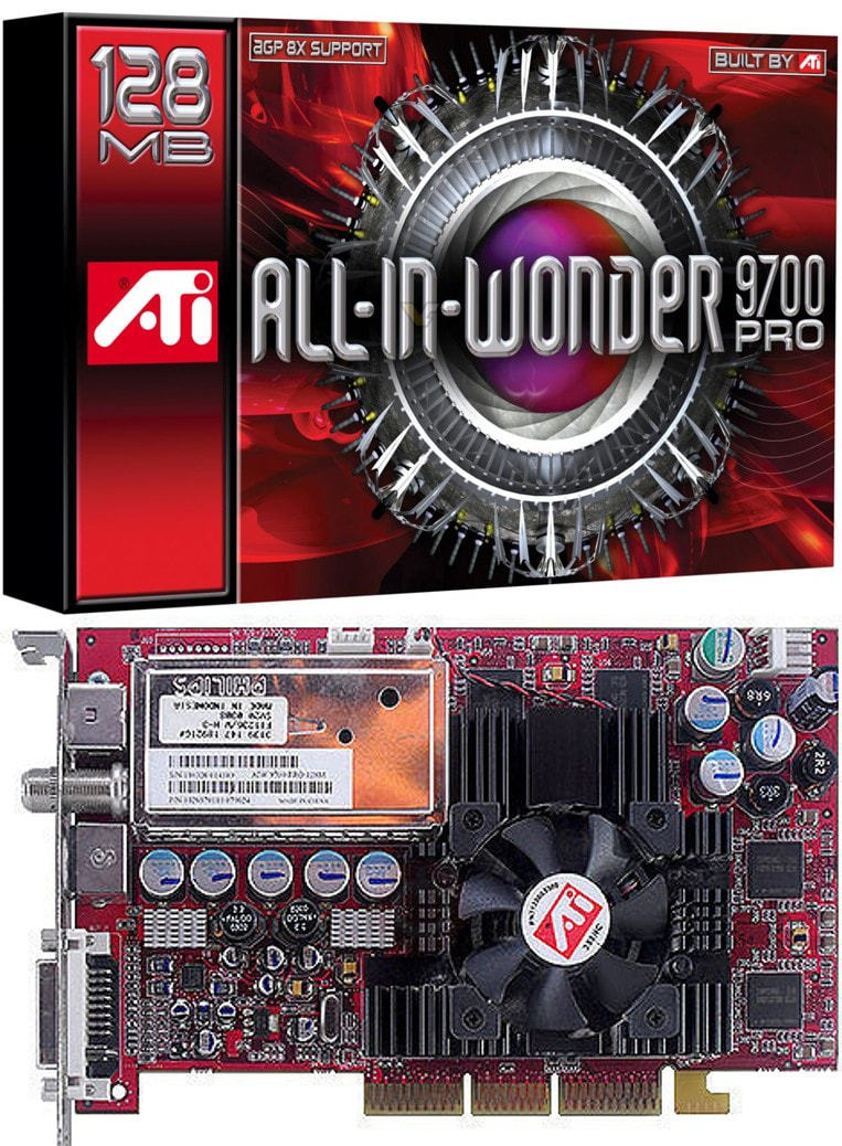
Around 2002 the ATI All-in-Wonder 9700-Pro was hot and about the best one could get as TV/video graphics processor. It used the FI1236, FM1236 of FQ1216ME. Note the large fan required to cool the Rage8 ATI processor.
|
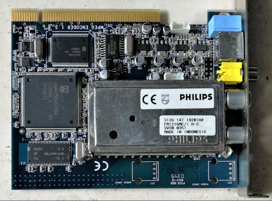
There were many applications of the Mk3 frontends, but this is a typical one: the FM1216ME/IH-3 on a KNC-One PCI card. Philips Semiconductors was also very successful in this segment, see the SAA6752 MPEG2 encoder and SAA7134 video converter and PCI encoder. [via Toh Kong Lim]
|
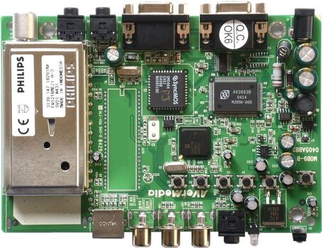
Another application: set top boxes. This is the Philips
FQ1216ME/IH-3 in an AverMedia TVBox9 small signal panel for (probably) LCD TV. The frontend was produced week 31 2004.
|
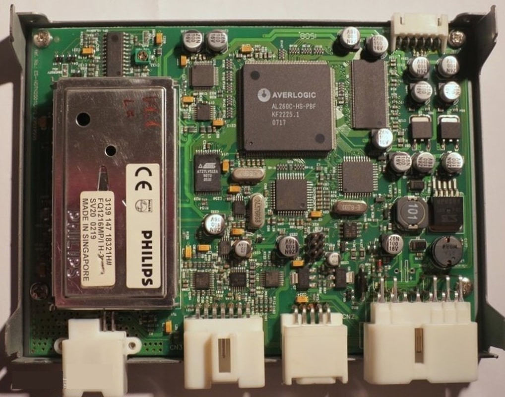
A more exotic application: the FQ1216MP/IH-3 multi-PAL front end in an InventCar Russian car TV module, which seems to be based on an AverMedia chip set.
|
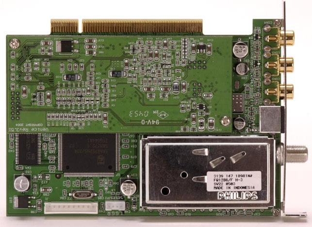
The Philips FQ1286/FH-3 Japanese NTSC front end on the SKNet Monster-TV PCI card. Note that the upper green surface is a second PCB panel.
|
|
Once the basic FQ1200-Mk3 was launched it became clear that in many TV and STB applications multiple tuner/frontends were required: record-while-play (Personal Video Recorder, PVR), dual window TV or the combination of an analogue and a digital frontend. Multi-tuner applications required some form of RF splitters, but the space was missing to build them into the module. The loop-through splitter versions FQ1200L-Mk3 therefore used a modified frame, with the internal partitioning moved 10mm backwards. This allowed a 3dB loop-through amplifier based on a BFQ540 broadband power transistor and the coupling transformer. There are quite some products, mostly for LCD-TV, based on the FQ1200L-Mk3, usually in combination with a regular FQ1200-Mk3. This was good business, with two Philips frontends per product!
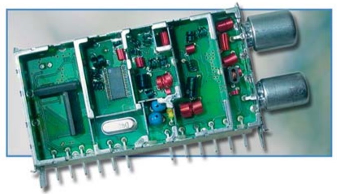
The only picture available of the Philips FQ1216MEL/IV-3 with active loop-through. [RF Solutions product leaflet 2003]
|
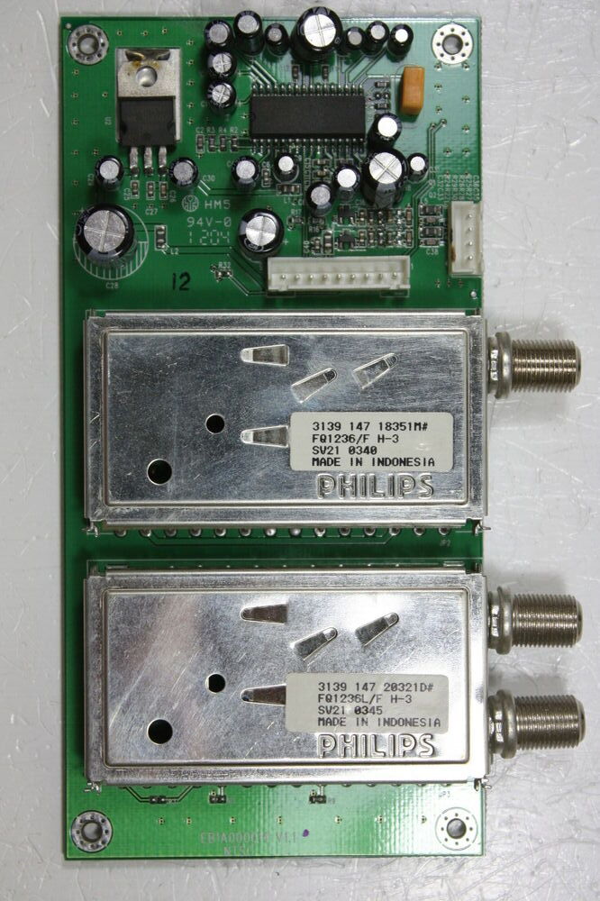
A typical dual tuner tuner board in LCD-TVs, using the Philips FQ1236L/FH-3 (below) and FQ1236/FH-3 (top). This was from an Akai PDP4249 plasma TV.
|
After the 2001 internet bubble dip the FQ1200-Mk3 was just in time to ride the recovery wave, and in 2002 volumes were already higher than in 2000 (4,4 vs. 3,4Mio) and continued to grow to 6,0 and 7,2Mio products in the following years. With all features (multi-standard in different combinations, QSS, FM-radio, active loop-through plus all connector variants) in combination with a fully recovered ingress immunity, the BL Tuners was back as the undisputed market leader in the Multimedia segment. It was thus also able to maintain very good margins, and by 2003 the sales of the 6Mio frontends were higher than the sales of the combined 17,3Mio TV tuners. Margin and profit contribution was of course also much better, and for 2-3 years the MM frontend business was the largest of the BLs Tuners and RF Solutions. With the benefit of hindsight, we can now say that the FQ1200-Mk3 family was business-wise the peak of the purely analogue Multimedia frontends, and the culmination of exactly a decade of very focused step-wise innovations. But the time of analogue-only frontends was soon over, digital TV was around the corner!
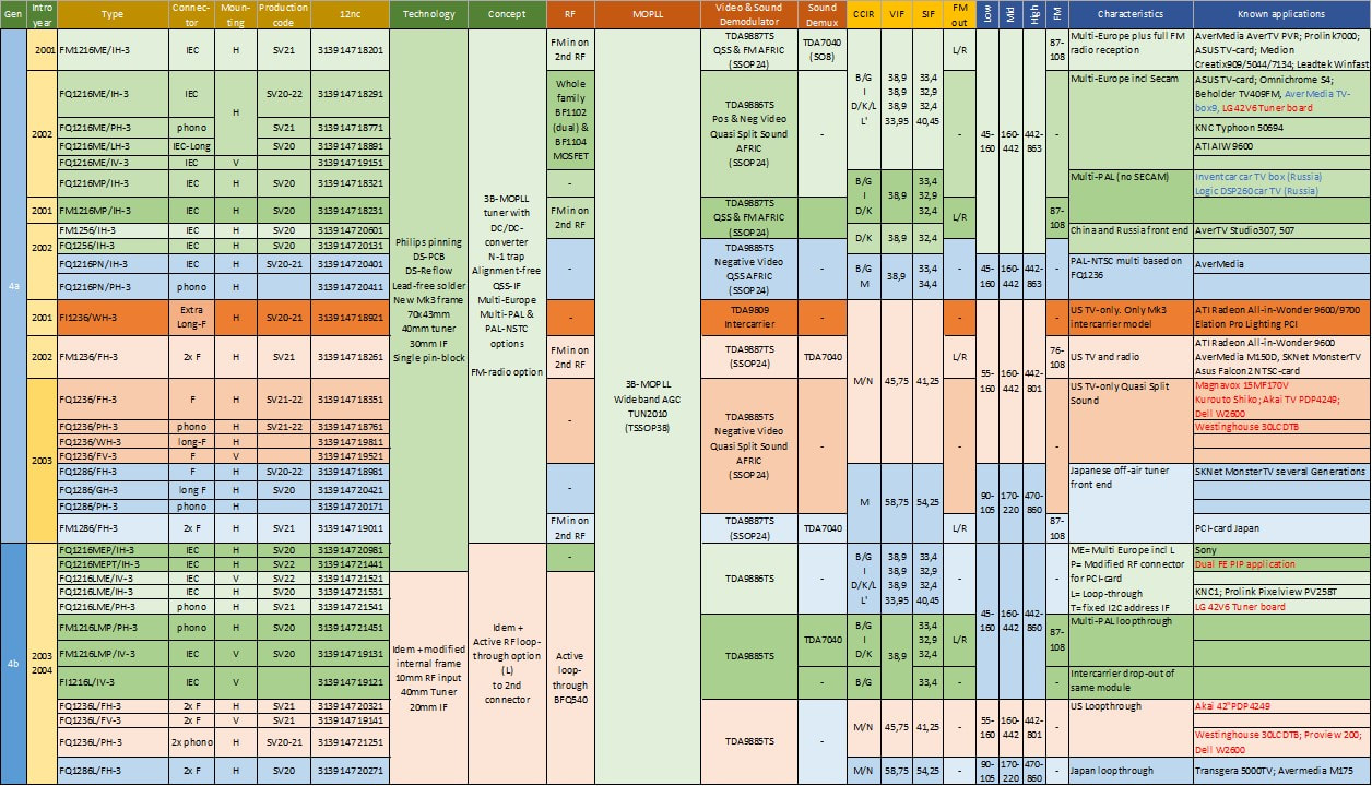
The Philips FQ1200-Mk3 family, including the FM1200-MK3 with FM radio. In orange the only intercarrier FI1236-Mk3. In the column "known applications" black refers to PCI cards, red to TVs and blue to others, e.g. STB or car TV modules. As the SV2x production codes indicate, all modules were produced in Batam.
FMD1200 and FQ1200-Mk4, building on the Mk3 success, 2004
The FQ1216ME platform, being so successful, was used for two extensions of the product portfolio:
- the FMD1216ME-Mk3, essentially the FM1216ME with DVB-T IF filtering.
- the FQ1200A-Mk4 ultra thin connector-less module
|
The Mk4 was triggered by the request of Nintendo, which produced the then famous and widely used Gameboy handheld game console also intensely used by my then young kids, for a much smaller and thinner frontend. The Mk4 was therefore based on an entirely new frame design, with the size reduced from 70x38 to 58x38mm and the thickness substantially lower from 12,9 to 6,9mm. These modifications had a number of consequences:
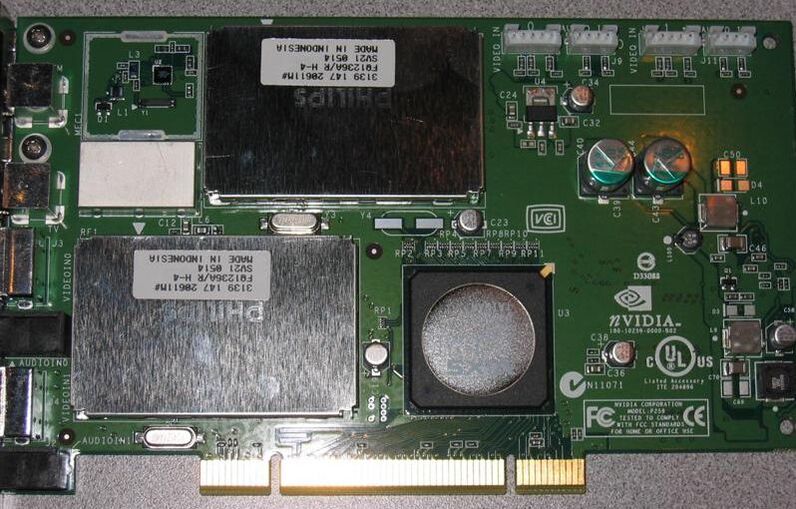
Two Philips FQ1236A/RH-4 frontends on the nVIDIA DualTV PCI-card with the big IC an nVIDIA signal processing IC.
The FMD1200 was triggered by the request from the German company Medion, which had a contract with the large German supermarket Aldi for 600.000 of their Creatix PC-cards that could receive both the standard (European) analogue standards as well as DVB-T. In other words, this was effectively the FM1216ME-Mk3 plus the RF/IF functionality of the TD1316-Mk2. As always, the devil is in the details, so some modifications were required:
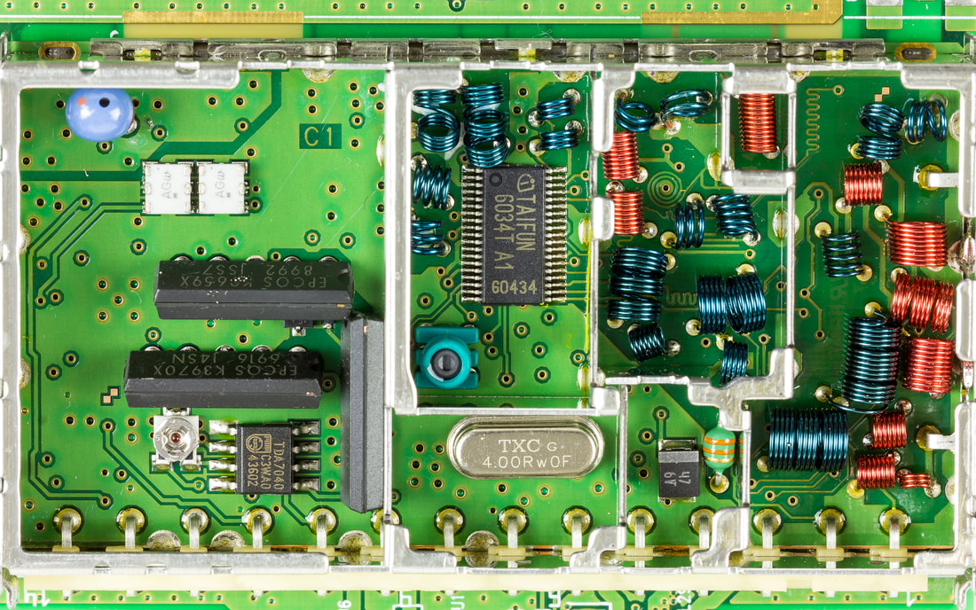
Very nice picture of the interior of the Philips FMD1216ME/IH-3. [Ronald Spekking on WikiCommons]
|
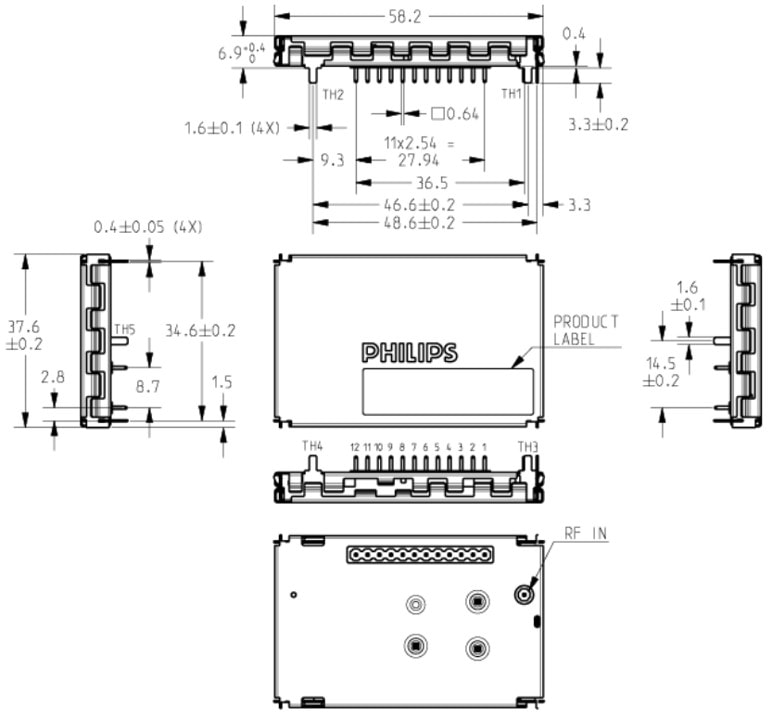
The Philips FQ1200A-Mk4 mechanics. [FQ1200AME-Mk4 Data Sheet, 6-2005]
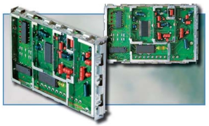
The only available picture of the Mk4 interior. On the bottom left the three SMD SAW filters. [Philips RF Solutions Product Leaflet, 2004]
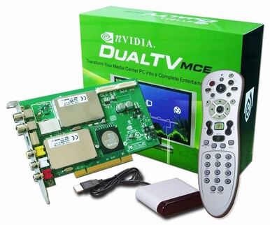
The nVIDIA DualTV box and its content.
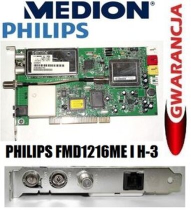
Joint Medion and Philips advertisement for their Creatix CTX926 PCI card and FMD1216ME/IH-3, respectively. Note that the card shown is a combi A/D Terrestrial and Satellite DVB-S (using the smaller Philips SD1878 on the right).
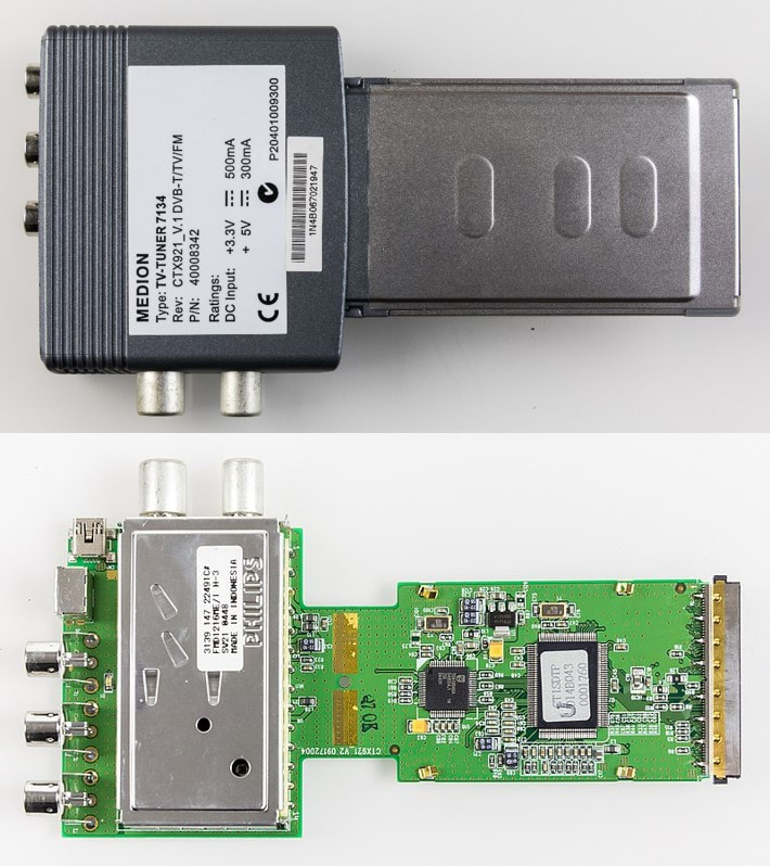
Another interesting Medion product using the Philips FMD1216ME: the Creatix CTX921 PCMCIA card. [Ronald Spekking on WikiCommons]
|
|
The FDM1216ME was clearly the main runner of this product group, but an NTSC version FMD1236 was also developed. Because of the less stringent phase noise requirements of ATSC it could use the cheaper TUN2010, and apart from the 44MHz ATSC SAW filter was otherwise identical. Much later, around 2006, probably on specific request of Asus, a version of the 1216 with diplexer was made.
|
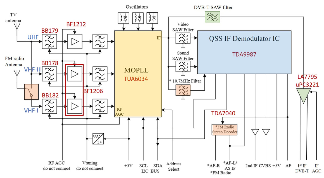
Block diagram of the Philips FMD1216ME-Mk3. In Green the DVB-T related functions added to the FM1216ME-MK3.
|
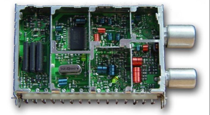
That it was not a very clever idea to split the tuner business into two entities, BL Tuners and BL RF Solutions, and keep them working on the same technologies is illustrated by above sample of the FQD1316ME/IH. It was developed in 2003 by the BL Tuners, one floor below the BL RF Solutions in the same TP3 building in Toa Payoh. It was based on the UV1318-Mk3 redesigned to the TDA6509 MOPLL and (probably, because invisible) the new TDA9987 AFRIC. On the left the three SAW filters for video, audio and OFDM are visible. The only differences with the FMD1216ME-Mk3 being developed one floor up were the WSP pinning, the omission of FM radio and the different MOPLL. But the latter choice killed the FQD1300, because the DVB-T phase noise performance was insufficient, that would have required the more expensive TUA6034 as used by RFS. After some prototype samples the project was stopped, and a WSP-based frontend was thus never launched. [via Edward Ng]
|
As said, the FMD1200 was a crash project, with the Medion request coming in early 2004 and a targeted release date by August that same year. And this despite the need to develop a new tuner, converting the mixed technology TD1316 OFDM tuner to the two-sided re-flow 1200 process. Development managed to squeeze three PCB cycles into this very short time and was able to pass Design Release in September. For this the BL received a formal letter of appreciation from Medion, a rare feat in the electronics industry. Production immediately ramped, but then disaster struck. The next month, October 23, 2004, the Chûetsu earthquake hit the prefecture Niigata in Japan, with at least three successive shocks of magnitude 6,6 to 6,9. This severely damaged the Sanyo Gunma plant, where the LA7995 IF-VGA was produced. A new crash project looked for a replacement solution, which was found in the NEC uPC3221. The footprint was identical, only requiring a small PCB change. But then initial samples got many customer complaints because of oscillations in the uPC, which turned out to be caused by its 10dB higher gain. When this was solved early 2005 production with the new VGA started. [Unfortunately, Sanyo business was seriously hit by the earthquake, from which they never really recovered. In 2010 the semiconductor branch was sold to ON Semiconductors, while the remainder of the company was taken over by Panasonic that same year.]
In the end the FMD1200-Mk3 was a very successful product, that ran in higher volume for Medion, Philips own PCI-card product line and other vendors, and as such it was a worthy extension of the FQ1200-Mk3 family. |
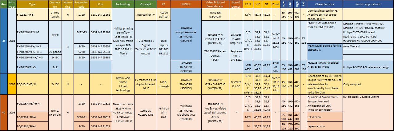
Overview of the two small Multimedia front end families: the FMD1200-Mk3 and FQ1200-Mk4. The top-most product, the last intercarrier frontend, was released as part of the Mk5 family but concept-wise part of the Mk3 and therefore listed here. The FQD1316ME WSP frontend was never released but is listed for completeness and comparison.
TU(V)1200 Network Interface Modules, 2003
The FMD1200 as described above, but also the FCV1236 from an earlier section, were both based on a step-wise move from the previous purely analogue frontends to hybrid analogue-digital solutions. In both cases this came down to adding an IF branch for the new digital standards. In parallel a quite different approach was also followed: purely digital Network Interface Modules (NIMs), which had started with the satellite SU1278. Terrestrial reception was next, both for DVB-T (OFDM) and ATSC (8-VSB).
|
Around the year 2001 the BL had been rolling out the FCV1236 NTSC frontend with ATSC down-conversion, with NextWave as one of the main ATSC players with its Nxt2002. It therefore had a joint program with NextWave to provide the optimal integral application solution for FCV1236 plus Nxt2002, which were demonstrated at the Consumer Electronics Show (CES) in Las Vegas in January 2003. When the BL defined the NTSC-ATSC TU1236 NIM including the ATSC channel decoder it therefore turned to NextWave. Also, because in the meantime the Philips ATSC IC developments (TDA9860 and 61) were killed due to the Components and Semiconductors US restructuring. At this time the default tuner solution for NTSC was still the FI1236-Mk2 based on the TDA5736 MO and TSA5523 PLL. (The FQ1200-Mk3 using the TUA6034 MOPLL was in development in parallel). The IF section contained the two 44MHz ATSC SAW filters and the LA7993 VGA in between to compensate for the high insertion losses, as well as the large 100-pins Nxt2002. Within the standard 89mm FI1200 frame a new 32-pin, still internal, pin block was used, no longer following the 1200 Philips pinning.
This TU1236D NIM must have been at that time, when first shown at the CES early 2003, a unique and very innovative product. There were, however, a few customer- and/or performance related new requirements:
|
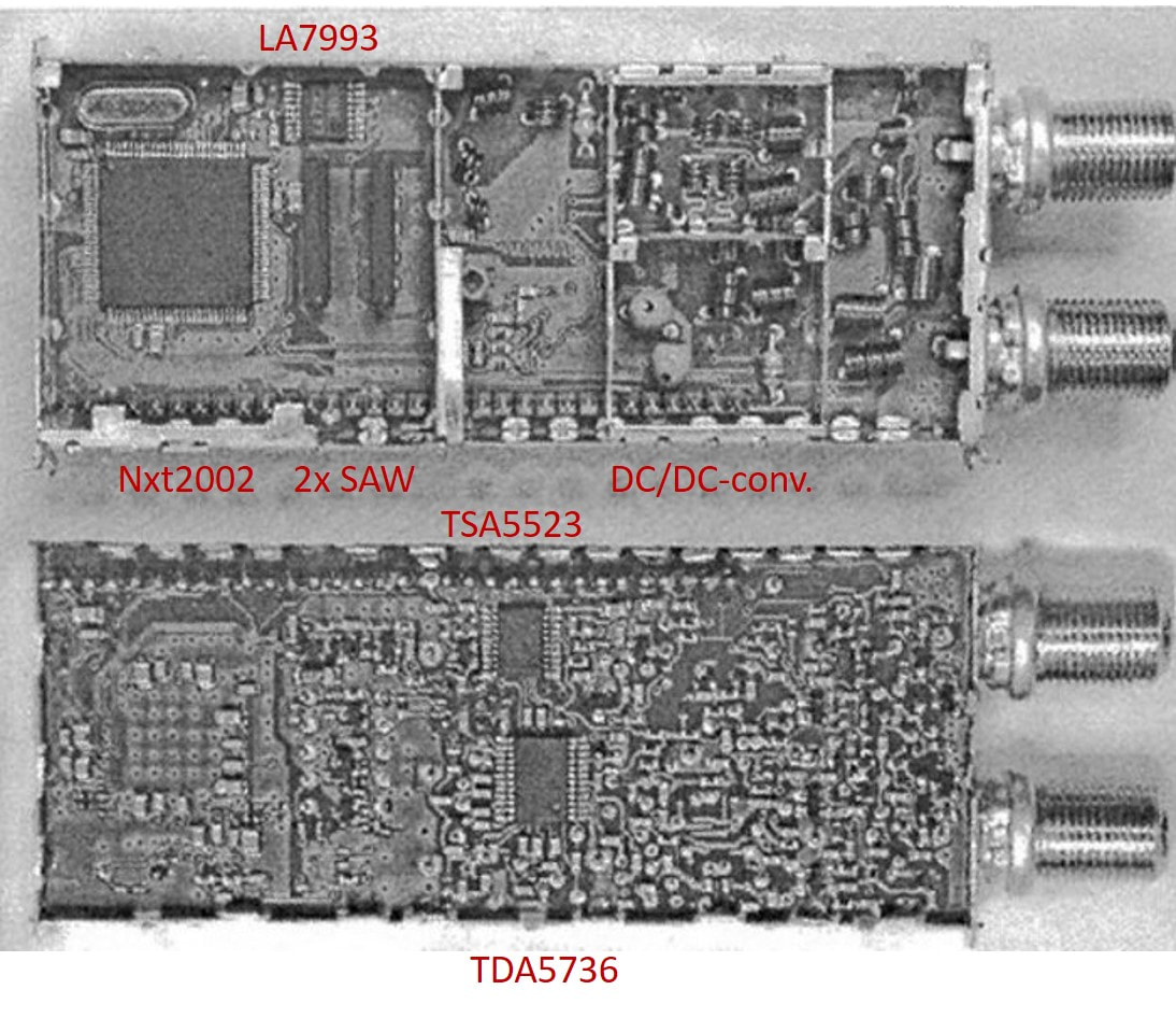
A very bad (copy from a scan) yet unique picture of the first Philips TU1236D ATSC NIM prototype from around 2002. All key components are indicated. It was, if at all, only used for sampling customers.
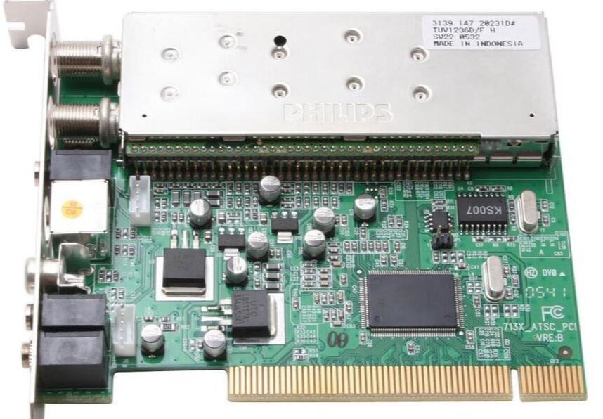
The Philips TUV1236D/FH on a KWorld ATSC-110 PCI card. The completely new way of external contacting is clearly visible.
|
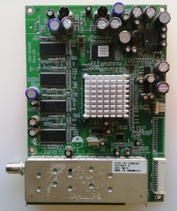
The single input Philips TUV1236/FH NIM on the Spectre Naga X73SV ATSC digital TV board.
|
To start, all RF and IF key components were replaced by next generation solutions, depending upon their availability. The MOPLL became the Infineon TUA6034, the IF-IC the TDA9885 AFRIC, and the 16-pin VGA LA7993 was replaced by the 8-pin LA7994. In the process the MOPLL and AFRIC moved from the A to the B-side, while the VGA moved to the A-side. To accommodate all functionality a new 100mm 1200-frame was used (97mm internal PCB size) and the now 40-pin connector moved outside the frame. It seems that quite some sampling took place based on this next generation prototype, where the channel decoder power consumption remained the main blocker for design-in. There was one fortunate development that compensated for these problems: the ATSC roll-out in the US was slow, and few customers already demanded fully integrated NTSC-ATSC hybrid modules. It was much safer for them to rely on optional ATSC add-on cards, using the FCV1236 instead. For the final product the BL had to wait till NextWave had ported its design to a smaller and lower power CMOS node (probably 180nm), which happened in 2004. Then, finally, the TUV1236D was launched based on the otherwise compatible Nxt2004. The dual input version re-used the high-isolation switch from the FCV1236, including the Peregrine IC and 4-layer PCB. It was then reasonably successful, being used in quite some Dell Computers and Humax STB digital boards. Around 2005-2006, when ATSC was made mandatory and the analogue switch-off was announced, customers switched to the ATSC-only TU1236. It is interesting to see how the product scope and key components changed between the first and the final models!
|
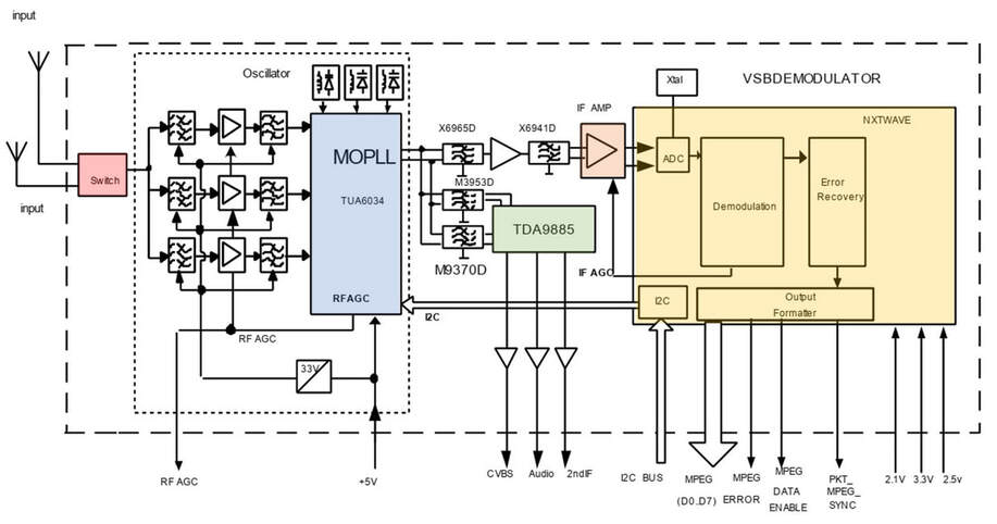
Block diagram of the Philips TUV1236D ATSC/NTSC NIM. [Philips RF Solutions TUV1236D Data Sheet, Oct 10, 2002)
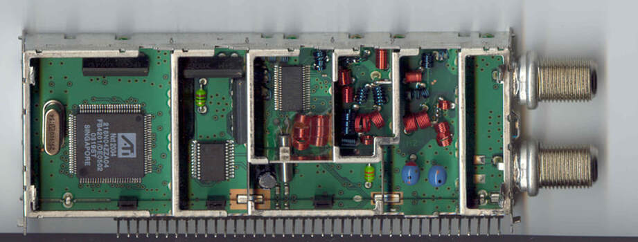
Picture of the final Philips TUV1236D/FV NIM. The 97mm PCB is partitioned from front to back in 10mm RF input, 42mm Tuner, 15mm analogue IF and 30mm digital IF. The 40-pin connector block with half-WSP pitch (2 instead of 4mm) is now on the outside of the module to save space. It still has the internal 5-33V DC/DC (the two blue inductors). The 4MHz crystal is not shared, so there are two of them: a new tubular one for the MOPLL and a standard one for channel decoder far left. [AnandTech.com]
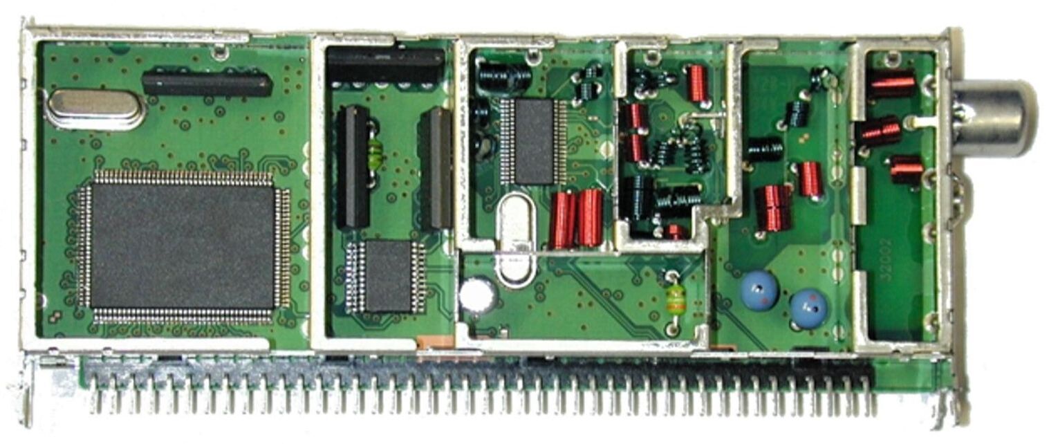
The final version of the TUV family, the TUV1236U/PV. This version used the ATI Theatre 341 IC, that also contained the Forward Data Channel demodulator. The unit thus thus contained the full Open Cable Uni-directional (= receive only) functionality.
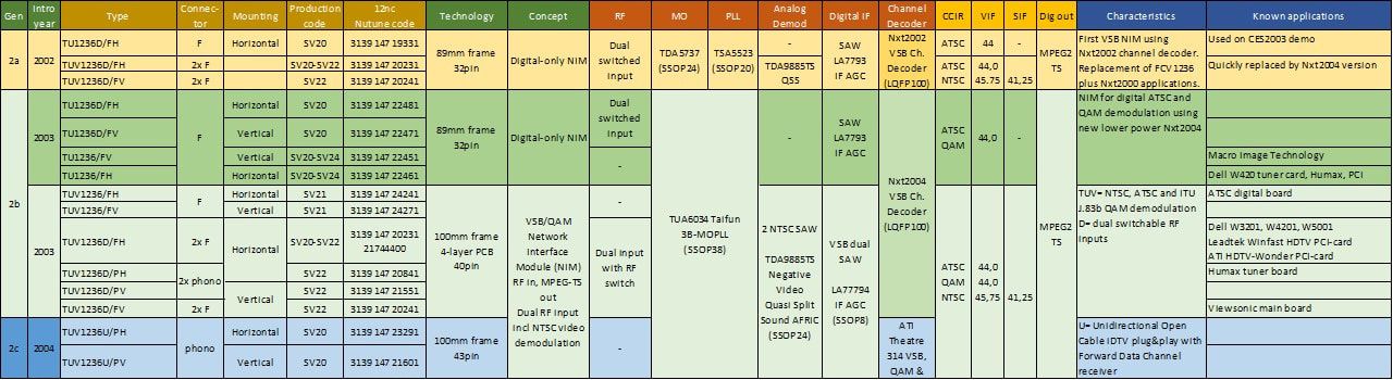
Overview of the three generations Philips TUV1236 ATSC/NTSC NIM family, mainly determined by the difference in ATSC channel decoder.
|
In parallel to the TUV1236 the DVB-T OFDM NIM was developed, although that one would remain purely digital TV only: the TU1216. Developments initially also started in Singapore in 2002, based on their standard TUA6034 MOPLL tuner and the NextWave Nxt6000 OFDM channel decoder. However, early 2003 it was decided that the concept would entirely change and be based on the Philips Semiconductors TDA6651 fractional-N MOPLL, which was much better on phase noise, and the new Philips TDA10046 OFDM channel decoder. The project also moved from Singapore to Krefeld. The core function now also included an RF loop-through, based on the BFQ540 power transistor. Because the 1200 footprint was smaller than the 1300 there was no room for the UHF modulator, but as an option the modulator output could be looped through from pin3 to the 2nd loop-through RF connector. DC power on the RF input connector, to supply an external antenna amplifier, standard on the TD1300, was also an option. The TU1216 was launched end 2003, slightly ahead of the TU1236 that was waiting for the Nxt2004. Because it did not contain the analogue demodulation, the entire function fitted in a standard 89mm FQ1200-Mk2 frame, using the new external 32-pin connector block. Whether it had to do with delays of the TUV1236 or not, but the TU1216 was initially also offered with 6MHz SAW filter, while maintaining the 36MHz IF. This way 64-QAM US or Latam cable applications could be served until the TUV1236 arrived.
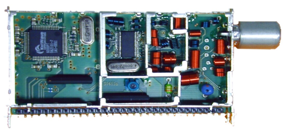
Interior view of the Philips TU1216/IHP DVB-T NIM prototype, based on the Nxt6000 OFDM channel decoder and in the centre the TUA6034 MOPLL. The TU1216 fitted in the standard 89mm FQ1200 frame and was thus smaller than the TUV1236.
|
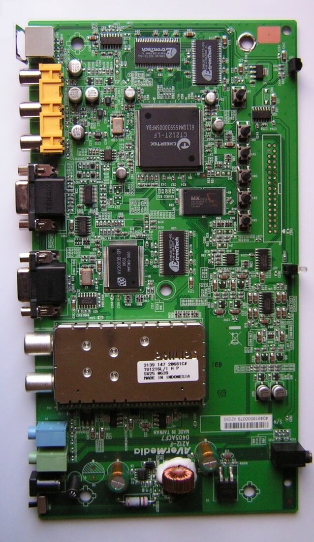
The Philips TU1216L/IHP DVB-T NIM on an AverMedia STB board.
|
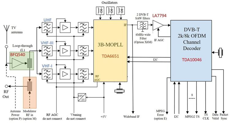
Block diagram of the Philips TU1216L DVB-T Network Interface Module. As indicated there was a major component update changing to Philips Semiconductors ICs.
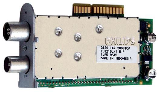
One of the main users of the TU-family was the German company Dreambox, which used exchangeable PCB modules as shown based on either TU, CU or SU1200 modules. Shown here is a 2nd generation TU1216L.
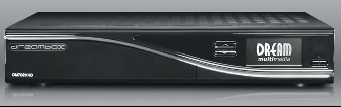
The company Dreambox in 2003 launched a series of re-configurable Linux-based Set Top Boxes that could contain one or more CU/TU/SU1200 NIMs. They were very successful. Here the Dreambox 7020.
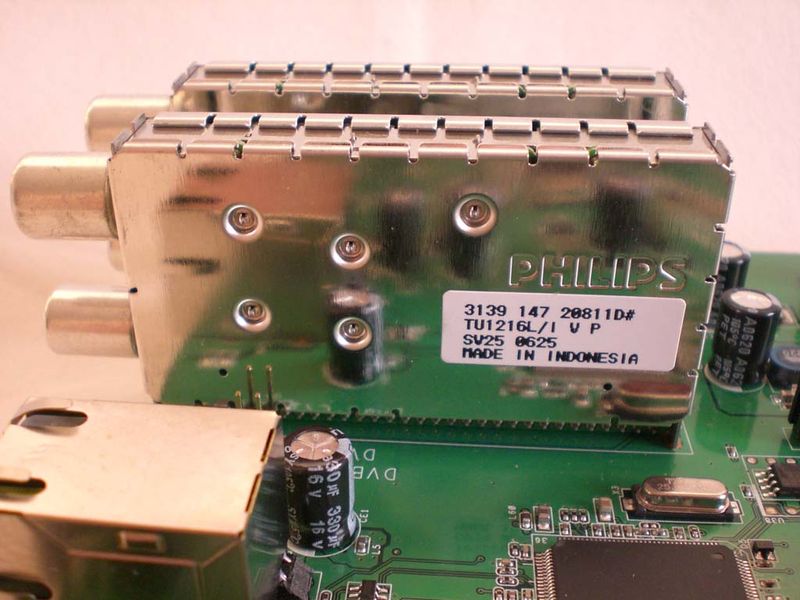
Pollin was another German company, offering complete STB mother boards. Either CU/TU or SU1200 NIMs could be used, which were mounted directly on the board. Here a Personal Video Recorder (PVR) board with two TU1216L/IVP of the second generation (SV25).
|
The TU1216 was successfully launched in 2003, finding its way into PCI-cards but especially STB and digital TV add-on modules. The 180nm CMOS TDA10046 turned out to be a very reliable IC. It used 10-bit ADCs at 53MHz clock frequency to oversample the 36,15MHz IF signal. One of its features was a "pulse killer". When the first OFDM demodulator ICs were released around 2000, it was found that they were quite sensitive to impulse noise. The OFDM modulation format is very robust to selective frequency fading and can counter sharp "nulls" in the channel transfer characteristic. But impulsive noise, so sharp time domain pulses caused by for example (bad) electrical motors in domestic equipment, has a very broad spectrum, which could upset the OFDM synchronization. The TDA10046 pulse killer was effectively an adaptive time domain switch that temporarily interrupted reception while maintaining synchronization. It was a very effective solution, making the TDA10046 the benchmark OFDM channel decoder for several years.
Although the TU1216 family was initially released with multiple options (Modulator RF in, MPEG error read out) the main runners became the very basic horizontal and vertical loop-through versions. It is good to see that the philosophy of the BL RF Solutions, to use completely interface compatible and interchangeable Network Interface Modules worked out. Based on the common "RF in to MPEG Transport Stream out" concept with compatible pinning a satellite, cable or off-air module could be inserted into the same mother board slot. This allowed the STB mother board to be channel independent and in principle without analogue signal handling. The German company Dreambox was probably the most loyal follower of this concept, using CU1200 (DVB-C cable), TU1200 (DVB-T terrestrial) and SU1200 (DVB-S satellite) modules from Philips across multiple generations of their boxes. The German company Pollin, offering mother boards, did the same. Other customers did not go as far with the channel exchange but did use a NIM for the reason of full channel functionality. 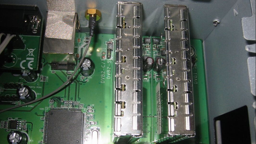
The same Pollin main board. The printed text clearly indicates the slot can be used for DVB-C/T and DVB-S NIMs.
|
The TU1216 was developed in Krefeld, but then quickly transferred to Singapore for volume manufacturing. Singapore development also took over the R&D ownership. Probably as a form of cost reduction the original full 3-band tuner was replaced by an off-air tuner, covering the VHF-III and UHF bands only. (In practice there were no DVB-T transmission in the VHF-low band). This was the TU1211.
As late as 2006 the TU1211 received and overhaul and the new TDA10048 channel decoder, becoming the TU1211-Mk2. This 2nd generation TU1200 was quite a success and was produced till at least 2008 when the company had become Nutune, a very long time in the digital world! At the same time, it can not be denied that NIMs were a relatively expensive solution, especially when the module was mounted on a PCB card first as done by Dreambox. And admittedly, the added value of putting the channel decoder inside a module was limited. Over time, the TD1300 OFDM tuner with internally the nasty dual SAW IF filtering, in combination with the channel decoder on the main board became the standard solution. No further terrestrial NIMs were developed.
As late as 2006 the TU1211 received and overhaul and the new TDA10048 channel decoder, becoming the TU1211-Mk2. This 2nd generation TU1200 was quite a success and was produced till at least 2008 when the company had become Nutune, a very long time in the digital world! At the same time, it can not be denied that NIMs were a relatively expensive solution, especially when the module was mounted on a PCB card first as done by Dreambox. And admittedly, the added value of putting the channel decoder inside a module was limited. Over time, the TD1300 OFDM tuner with internally the nasty dual SAW IF filtering, in combination with the channel decoder on the main board became the standard solution. No further terrestrial NIMs were developed.
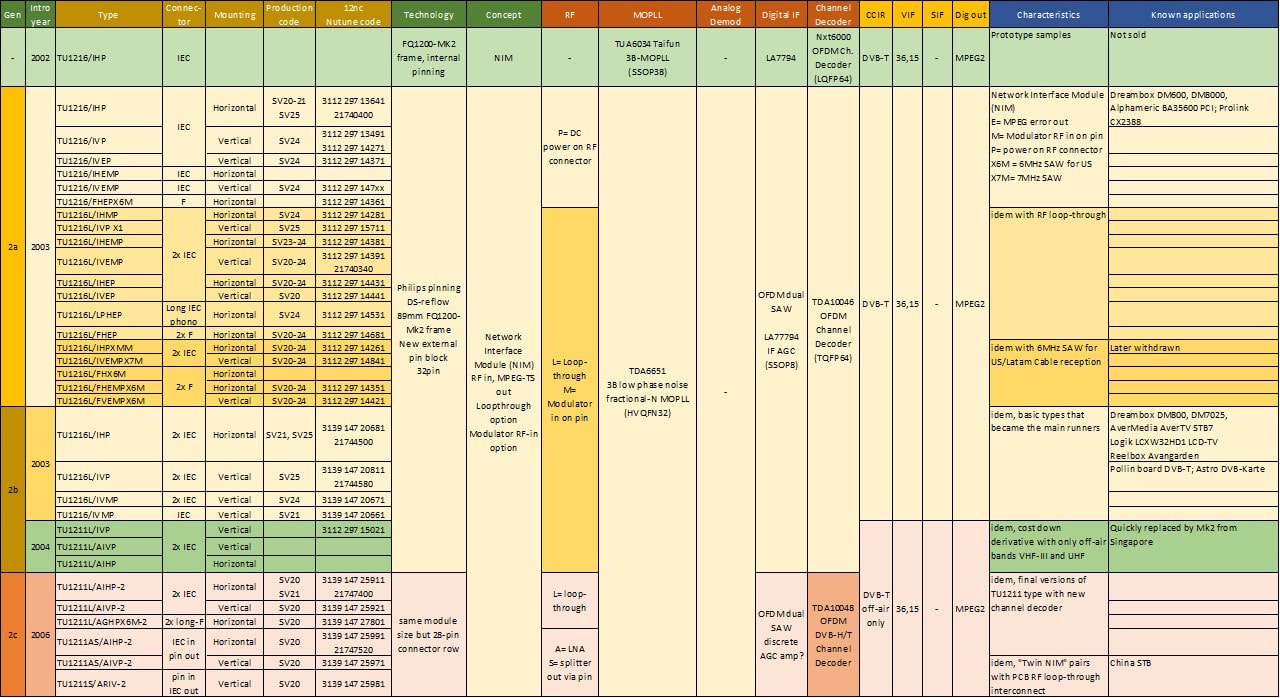
Overview of the Philips TU1216 DVB-T NIM family. All products with an SV2x production code have been produced and sold, although the application is not always known.
DOCSIS and OpenCable cable network developments, 2001
Cable networks for distribution of TV and radio broadcast signals existed for decades, and towards the nd of the 20th century had adopted digital video standards. In Europe DVB-C using 64-QAM, in the US an almost identical 256-QAM format was selected by the cable operators, which was later made official as part of the ATSC-Cable standard (although the ATSC preferred 16-VSB on the cable, but that never found any support). With the rapid emergence of the Internet, it is obvious that cable operators also wanted to use the cable network for high speed internet access of the consumer homes. To this end an industry consortium called Data Over Cable Service Interface Specification (DOCSIS) was formed, which adopted a standard developed by CableLabs with the support of all major US cable equipment suppliers and service providers. DOCSIS1.1, the first real version, was released in 1999. It allowed 38Mb/s data downstream to the consumer (after extraction of overhead), using the standard 256-QAM modulation in a 6MHz "NTSC" TV channel. Obviously, the data was now not used to encode digital TV signals but was IPv4 compatible internet data using the Ethernet IEEE 802.2 data link protocol. More importantly, it added an upstream data channel using QPSK or 16-QAM (depending upon the available SNR) at 10Mb/s (DOCSIS1.1) and 30,7Mb/s (DOCSIS2.0) over a 3,2MHz channel. These upstream channels were allowed between 5 and 42 MHz, below the VHF-I band. DOCSIS1.1 included Quality-of-Service provisions, allowing Voice-over-IP.
|
DOCSIS was quickly adopted as de facto solution and was taken over more or less integrally in Europe, but modified to European standards (7-8MHz channels, 64QAM). This was called EURODOCSIS.
The US cable modems quickly found their way to the consumer, dominated by big players like Motorola, Scientific Atlanta, and General Instruments. This somehow limited competition and was one of the drivers for CableLabs to come with the OpenCable standard. This specified in much more detail each of the (frontend) functions of a cable box, with the ambition that more suppliers could offer (partial) products. |
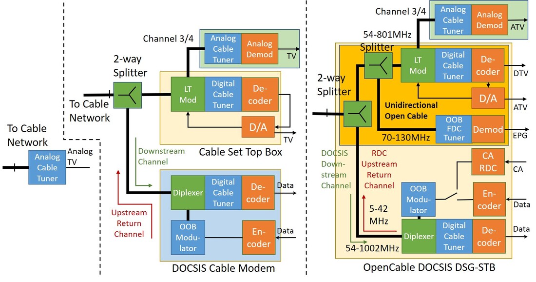
Evolution of the (US) cable consumer premises system. On the left a standard cable TV receiver without any signalling, up to the mid 1990s. Centre the emergence of two parallel solutions: digital cable STB (top) and DOCSIS cable modem (bottom), usually supplied by different vendors (2000-2005). Right the final integrated system based on OpenCable and DOCSIS Set-Top Gateway (DSG) specifications (around 2010). This is the US DOCSIS view, but Europe was not fundamentally different, it had the upstream band extended to 65MHz and receive of course to 860MHz. RF Solutions focused on the green and blue functional blocks. The dark yellow box covers the so-called Unidirectional Open Cable receive-only function, that was covered by the TUV1236U NIM.
|
The OpenCable spec defined a complex STB-modem architecture, with multiple RF signal streams:
- the 256-QAM encoded digital TV signals (called Forward Application Transport Channel, FATC), occupying the standard 6MHz NTSC-compatible channels between 54 and 1002MHz. (Although at least for many years nobody used this extension, so 801MHz remained the practical US upper limit). By the way, free analogue NTSC channels could still be present on the cable! In EURODOCSIS the values are of course 64-QAM from 48-860MHz with 7 or 8MHz channels.
- 256-QAM internet IP data traffic downstream to the modem receiver, occupying the same 6MHz-spaced channels. For EURODOCSIS the same as above.
- the upstream Out-of-Band (OOB) DOCSIS channel for the modem, up to 30Mb/s 16-QAM in 6,4MHz channels between 5 and 42MHz for DOCSIS2.0. For EURODOCSIS the frequency range is 15-65MHz.
- an additional OpenCable upstream Reverse Data Channel (RDC) for the STB, especially for exchanging verification and customer specific data related to the Conditional Access (CA). This used the same OOB channels as DOCSIS, only at a ten times lower bit rate. Only one of the two return channels (DOCSIS or RDC) could be active.
- an additional OpenCable downstream OOB Forward Data Channel (FDC). This allowed transmission of Electronic Program Guide (EPG) information to the STB even when a modem was not present or not active. This was QPSK encoded up to 3Mb/s in a 2MHz channel between 70 and 130MHz (so formally out-of-band between VHF-I and VHF-III). It was also referred to as DOCSIS Set-Top Gateway (DSG).

The traces of Philips in cable modems are minimal, so it seems that the company did not produce cable modem boxes. Around 2000 the Philips Semiconductors product line Broadband Access developed DOCSIS1.1 modem ICs, like the PTD1100 Venus shown here. This was another BL that did not survive the Philips Components and Semiconductors Sunnyvale dissolution in 2002.
|
In its most complex for an OpenCable/DOCSIS integrated STB-modem thus contained three tuners, two modulators and four splitter-diplexers. It was up to the RF suppliers like the BU Tuners, together with their customer system architects, to figure out what the optimal partitioning was of all these RF functions. Obviously, all this was an expensive system solution, and over time especially the FDC tuners were deleted, based on the assumption that most customers did have internet access for signalling. The basic DOCSIS standard also saw its proper evolution to ever higher performance: DOCSIS2.0 in 2002 (30Mb/s upstream data) and in 2006 DOCSIS3.0, the latter allowing higher order modulation upstream (64QAM) and OFDM and channel bonding downstream, such that the downstream speed increased to maximum 1,2Gb/s (24 channels bonded) and the upstream to 200Mb/s (8 channels bonded). By this time DOCSIS and EURODOCSIS had merged into a single standard, albeit with the different channel spacing and modulation as before.
|
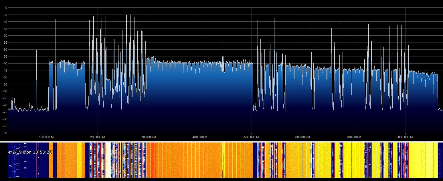
The RF spectrum of a typical DOCSIS2.0 cable network, clearly showing the flat QAM channels and the analogue PAL channels. The challenge of adjacent channel interference is now obvious. From the spectrum it is impossible to see which QAM channels are used for digital TV and which for internet, but the latter are often at the higher frequencies.The spectrum is measured after the diplexer, so the empty area on the left is for the upstream channels. [Tweaker.net forum]
Tuner Theory 17: Dual-conversion vs. single-conversion tuners
In the 50 years covered by this (Philips) TV tuner history, all tuners described have invariably been of the same architecture: a single conversion step from the RF input to the low Intermediate Frequency (IF) used by the demodulator. There was one single exception: the (in)famous Weinerth Tuner project at the Philips Research NatLab during the early 1970-ies, which pioneered and patented double conversion. After the Weinerth project failed, at least in the world of standard TV tuners the double conversion concept was effectively dead. It was therefore a surprise that the concept popped up again in the US as the primary architecture used in cable tuners.
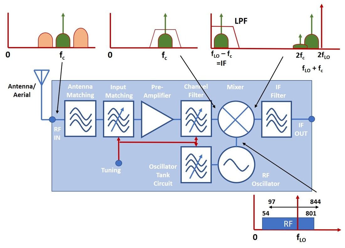
Basic architecture of the single-conversion tuner, as used for off-air and cable reception. One of the core characteristics is that the LO frequency range and RF receive band almost overlap, with breakthroughs as the main channel.
|
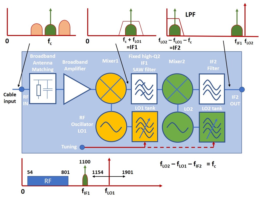
Dual conversion for US Cable, where the first high-IF is set at a typical value of 1100MHz. LO2 is then fixed at 1143MHz. The biggest risk in dual convergence is beats between the two LOs. To avoid beats, LO2 can also be tuned (slightly) as long as the general relation shown for fc remains valid.
|
The concept of all dual conversion tuners is 100% according the very first Philips patent by Dr Hans Weinerth: a broadband input, a first mixing stage with a high out-of-band LO that mixes the wanted channel up to a high, fixed first IF. In the Weinerth tuner this was around 3GHz, most practical tuners used a first IF between 1 and 1,5GHz. By this time high frequency SAW filters were available (from Siemens) providing channel selectivity, followed by a second mixer that converted the signal to the second IF (45,75MHz picture carrier for NTSC, 44MHz centre frequency for 256-QAM). If we compare single and dual conversion performance, the main differences are:
- with dual conversion the LO(s) are far out of band, avoiding image rejection and in-band LO radiation problems.
- dual conversion tuners do not have tunable signal filters, only one tuned LO1 tank, and therefore no tracking problems. For the same reason tilt, VSWR and group delay hardly vary with frequency and are much more constant, mainly determined by the SAW filter.
- single conversion tuners are around 10dB better on phase noise, first because there is only LO (saves 3dB) and secondly because the LO frequency is roughly 2x lower (gives 6dB).
- the tuned input of the single conversion tuner gives much better Noise Figure than the broadband resistive input of the broadband dual conversion amplifier. The dynamic range of the single conversion tuner is therefore also much higher due to its double-tuned concept. To come to acceptable IP2 and IP3 the double conversion tuner uses a lot of power to keep the broadband amplifier in a linear mode.
CDM1500 and CDX1200 cable tuners, 2000
Digital cable tuners started with the TD900 and CD1500 modules already in 1995, but pick-up of the market was slow. In the US Philips was battling with the dual conversion religion and not making many inroads, while in Europe it took a while till EURODOCSIS1.1 was finally established as a de facto standard. In the meantime, with the first generations products important lessons were learned: for cable the RF application in front of the real tuner was critical, if not most important. As the system block diagram in the DOCSIS section above shows, a typical cable STB or modem contain at least one splitter/loop-through/diplexer and modulator.
|
The first such product was the CDM1500 (Cable Digital Modulator, 1500 is WSP-compatible pinning). Because the 1500 was a sizeable frame there was plenty of room for different RF input functions:
|
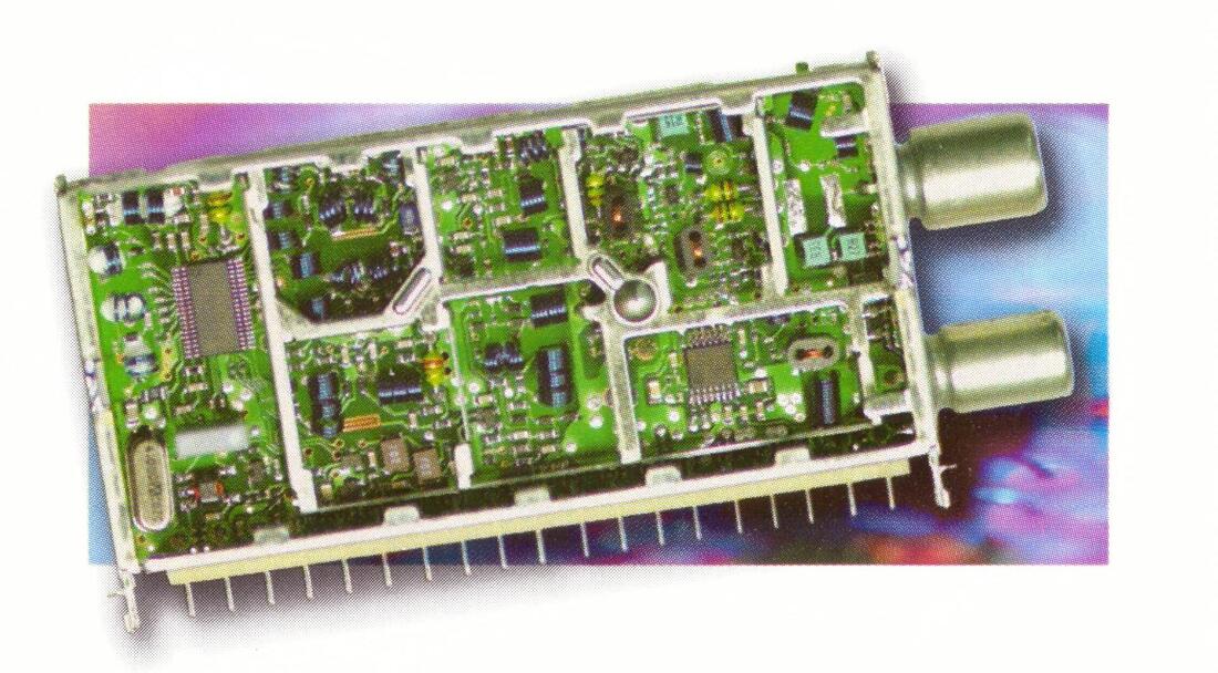
The only picture of the Philips CDM1500 digital cable tuner with modulator, visible lower right inside the module. Upper left the new MOPLL. [Philips RF Solutions product leaflet, February 2004]
|
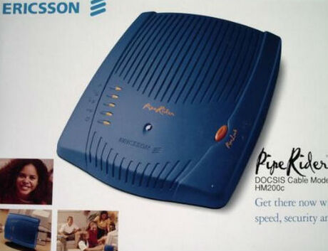
The Ericsson PipeRider HM200c DOCSIS1.1/EURODOCSIS 256/64-QAM cable modem. Thanks to the horizontally mounted CDX1200 it had a very low profile. [Ericsson HM200c user manual, 2000]
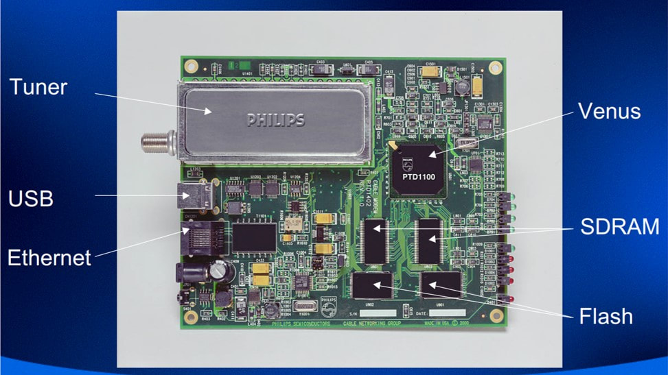
The Philips 256-QAM DOCSIS1.1 reference design, based on the highly integrated PTD110 Venus IC and the CDX1236 tuner. [Philips PTD1100 Single-Chip Cable Modem Gateway product leaflet, 2001]
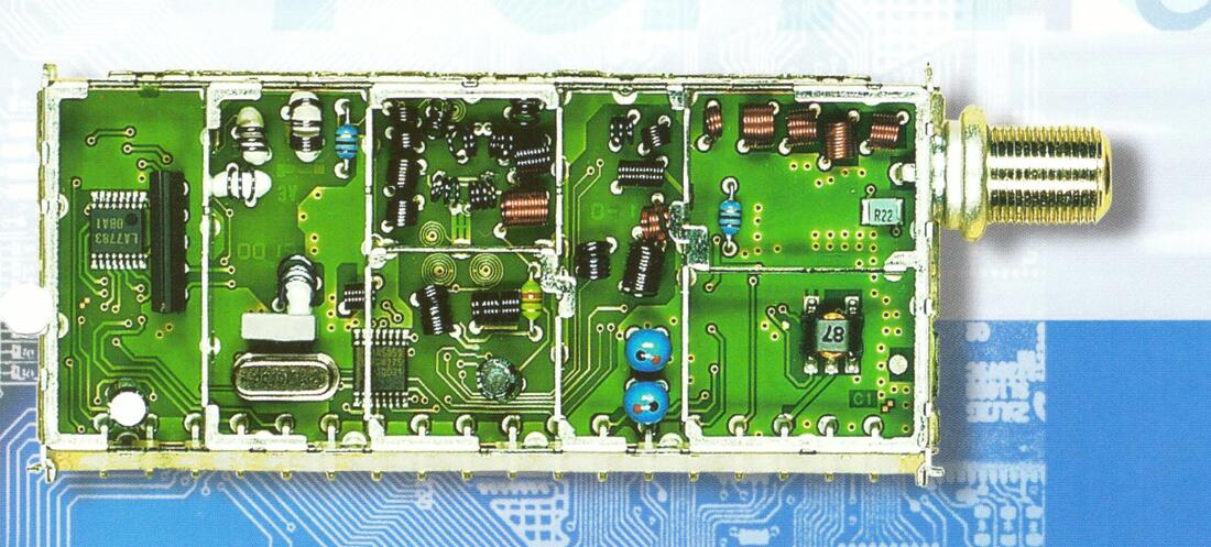
The Philips CDX1200 QAM tuner. Note the diplexer transformer lower right. The SAW and VGA are far left. The two blue inductors belong to the DC/DC converter. Also note the TSA5059 PLL. [Philips RF Solutions product leaflet, 2000]
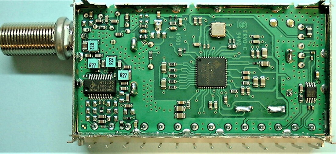
Prototype of the Philips CDX1236-Mk3 digital cable tuner based on the single-chip Microtune MT2040 IC. It developed serious over-heating problems and was therefore never taken into production. [Via Edward Ng]
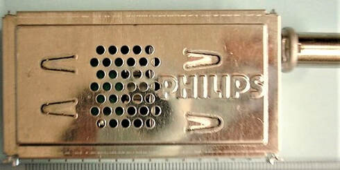
B-side view of the Philips CDX1200-Mk3, with the added ventilation holes overhead the MT2040 IC. [Via Edward Ng]
|
The next product was based on the 1200 family, mainly because of its smaller size and standard horizontal mounting: the CDX1200 (Cable Digital DipleXer). This product was driven by the Silicon Valley internet developments, with two main customers: Philips Semiconductors and Ericsson. Both were large European companies that had convinced themselves they should be in Silicon Valley to ride the wave of success of the emerging companies there. Ericsson's US team developed the first product for the new in-home equipment product division. It was called the PipeRider HM200c and was one of the first compact QAM DOCSIS/EURODOCSIS modems. With a mix of high integration and the horizontally mounted CDX1200 a revolutionary compact modem was designed. It survived the internet bubble in 2001, but in 2003 Ericsson had to cut its losses in the mobile phone division and closed its US lab. But up to then Ericsson became the single biggest customer for the CDX1216 (EURODOCSIS) and CDX1236 (DOCSIS1.1), using 600.000 modules. In parallel Philips Semiconductors used the CDX1200 as the tuner on their cable modem reference board around the PTD1100 Venus 256-QAM modem IC. Many samples were sent by the Tuners Singapore Development to Sunnyvale, and the design passed the CableLabs approbation tests, but then the whole program came to a grinding halt when the Philips Components and Semiconductors activities in Sunnyvale were closed. Although it was tried to sell it to other customers, the cable modem market at the time was quite uncertain, people still struggling with the DOCSIS introduction. Ericsson therefore remained the only real customer.
The CDX1200 itself used the FI1200-Mk2 technology and frame, but with the tuner moved backward compared to the FI1200 to make room for the RF functionality. It was one of the very last BU tuners using a separate MO and PLL, using the 2,7GHz low phase noise Philips TSA5059 PLL. Half the traditional IF section was used for a QAM SAW filter (at 36,16 or 44MHz) and a Sanyo LA7783 AGC IF amplifier to provide 2Vpp IF for data converters. The large input area was used for the mentioned RF functions, especially the diplexer transformer taking a lot of room. The biggest difference with classical tuners was that it used only two bands, VHF-III and UHF. This was because the return path occupied the 5-42MHz (CDX1236) or 5-65MHz (CDX1216) frequency bands. Because the upstream modulators were quite new and different, there were two versions of the CDX1236, for the Analog Devices (extension D) or Anadigics (extension R) solutions. One interesting development closes the CDX1200 chapter. Around 2001 the US company Microtune was making a lot of noise in the market with its integrated dual-conversion cable tuner, which had developed into the MT2040. It was aggressively promoted in countries like Taiwan and Korea, but most customers were very hesitant to put a tuner IC directly on their PCB. BU Tuners had been in contact with Microtune since 1999 and had visited them at Plano. It now smelled an opportunity and, after many legal hurdles on both sides, signed a very detailed NDA about the MT2040 evaluation. Obviously, Microtune was very anxious that information would leak to Semiconductors Caen! Singapore developed a module based on Microtune ICs equivalent to the CDX1236. Because it used the shortened 70mm 1200 frame of the FQ1200-Mk3 it was called the CDX1200-Mk3. It used the MT2040 as core as well as the MT1630 upstream amplifier. However, major heating problems emerged. Although Microtune claimed substantially reduced power consumption (1,5W) the IC inside a closed module heated up to 105 degrees Celsius, leading to serious reliability challenges. In trying to combat the heating problem the B-side cover was perforated with some 40 holes to provide air circulation, but the issue was never really solved. The only time the BL violated its "belief" in single-conversion tuners, exploring a dual-conversion solution, thus did not result in an actual product. No further co-operation with Microtune, the Angstgegner of the BL TV Frontends, was explored. But the side effect was a sharply increased pressure on the Caen organisation to come with an internal Si-Tuner solution for cable. |
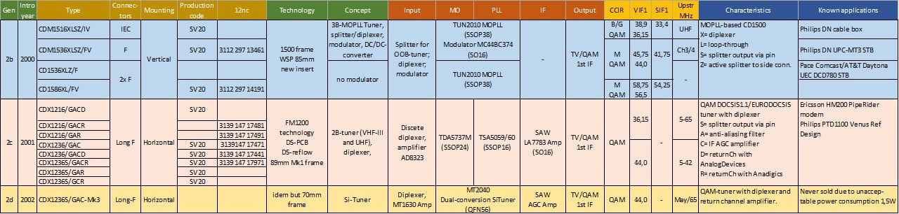
Second generation Philips digital cable tuners, the CDM1500 and CDX1200 families.
CD1300 cable modules, 2001-2005
Because digital cable was primarily a STB and Cable Modem application, and much less a PC Multimedia, the CDX1200 was considered an interim solution, and the main cable tuner successor of the CD1500 WSP tuner was thus again a WSP-compatible module: the CD1300. The different versions of the CD1300 followed each other quickly, mainly driven by changes of the MOPLL. The CD1300 re-used the 65mm WSP frame introduced with the UV1300A and T tuners, and also used by the TD1300 OFDM tuner. The concept was a direct 1:1 copy of the CDM1516 tuner section, using the Infineon TUN2010 MOPLL. To offer solutions for the many possible RF input configurations, the tuner provided optional loop-through (L), diplexer (X) and passive splitter with output via a pin (S) functions. Like the CD(M)1516 it still did not contain QAM SAW filters and/or an IF amplifier as offered in the CDX1200. The CD1300 was introduced in 2001 and did not live for very long but had the leading European STB maker Pace as main customer. Quite exceptionally, Pace also required a US version, the CD1336X, since they also tried to get a foothold in the US. BU Tuners gave them a lot of support, since this might be the entrance of their single conversion tuner in the US market. Unfortunately, this was not the case, the US cable market stayed closed for the Philips tuners.
|
The Mk1 was rather quickly succeeded by the Mk2, which introduced three functional upgrades:
|
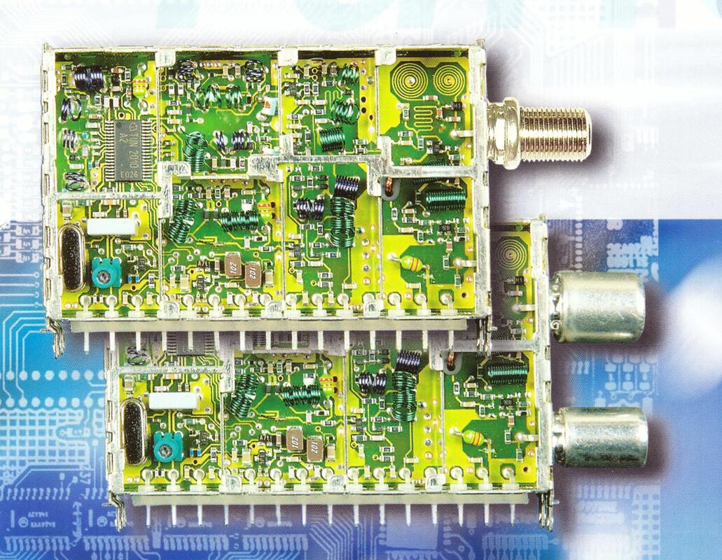
The Philip[s CD1300(L) digital cable tuner. On top the CD1336/FV, below the CD1316L/IV. [Philips BU Tuners product leaflet CD1300, 2001]
|
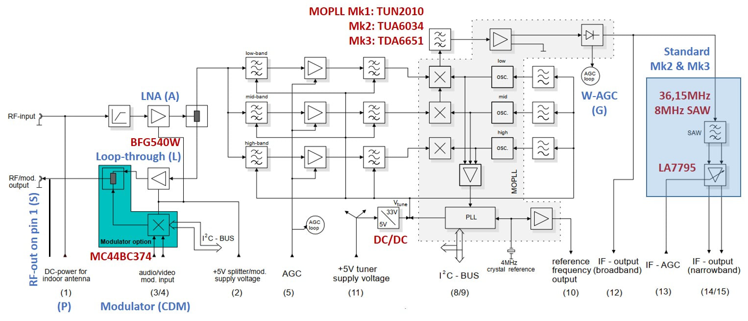
The Philips digital cable tuners CD(M)1300(L) were conceptually all identical, with the IF SAW filter and VGA introduced from the Mk2. Most options and differences were related to the RF input circuitry: LNA, loop-through and modulator.
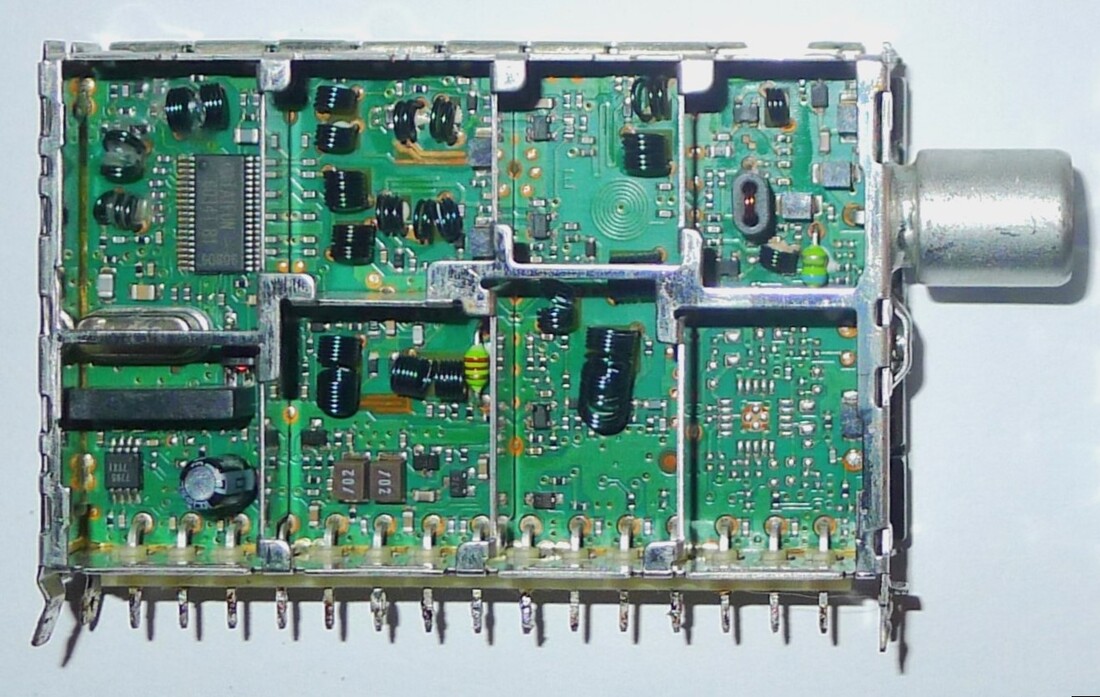
The upper half of the twin tuner set, the CD1316AS/IVP-2. Upper left the Taifun MOPLL, lower left the SAW filter and LA7795. [via Maarten Bakker]
|
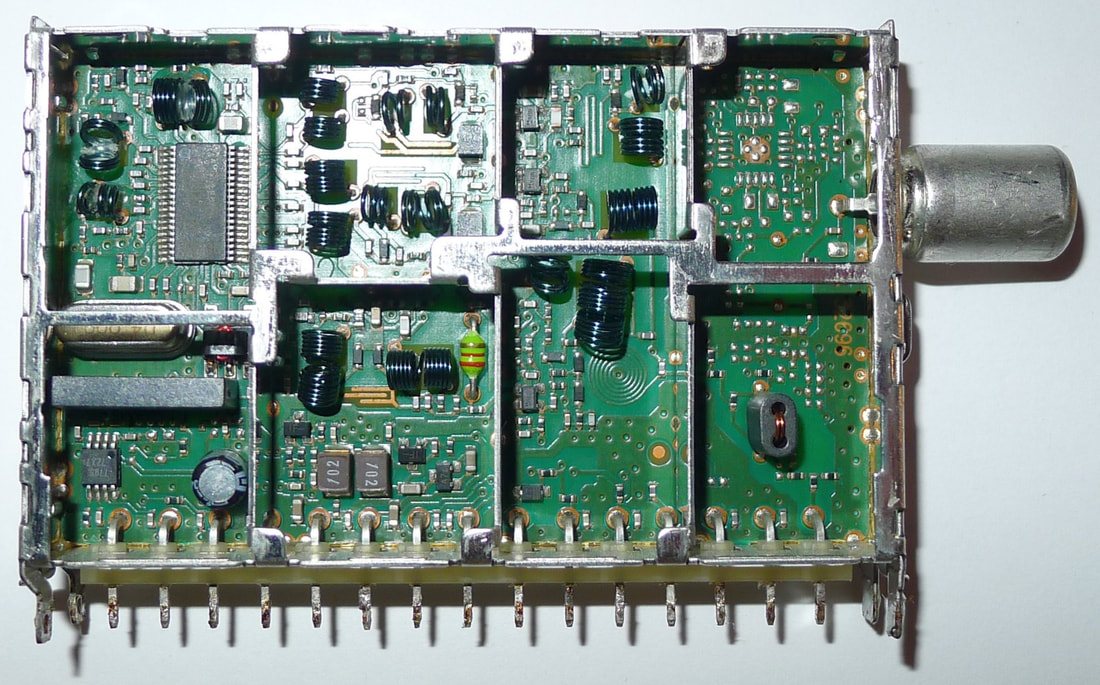
The lower half of the twin tuner, the CD1316AL/RIV-2. Not that in the front sections the (unused) layouts of the modulator sections in the two tuners has been flipped. [via Maarten Bakker]
|
|
One interesting application was developed as part of the CD1300-Mk2, the "Twin Tuner". This was envisaged for dual digital tuner applications, e.g. view and record IPVR boxes. To reduce the number of RF connectors and cables, part of the RF loop-through path was via regular pins and the customer PCB. The concept was probably prepared for US cable too, since it contained the typical NTSC loopthrough switch, i.e. when using the modulator the loop-through is disabled. When the modulator was active the loop-through path was disconnected using an RF switch, a concept not seen in any other product. The same concept would also be implemented with the TD1300-Mk2 OFDM tuners.
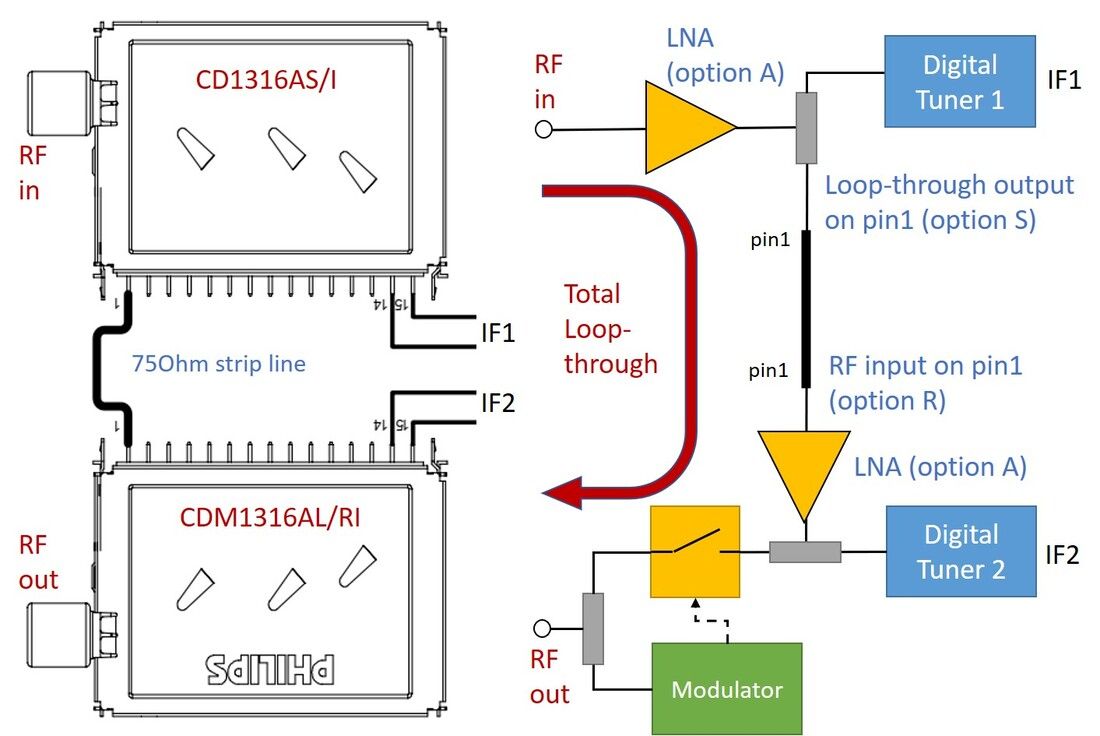
The Philips "Twin Tuner" application, for applications where two digital tuners were required including a loopthrough and re-modulator to an analogue TV, VCR or DVD. The connection between the two tuners was made across the PCB. [Philips RF Solutions CD1316AS-Mk2 and CD(M)1316AL/R-Mk2 Tuner Modules for Analog and Digital Cable (QAM) "Twin Tuner" Applications, 23-9-2005]
The CD(M)1300-Mk3 introduction in 2005, was triggered by the switch to the Philips Semiconductors TDA6509, which was a much better low phase noise MOPLL. Because it was a fine-pitch leadless HVQFN IC it was rotated 45degrees for soldering. The RF input functionality had by now standardized to a loop-through with/without the modulator. The CD1300-Mk3, as final version of this development, ran very successfully until at least 2009, with big customer Humax but also many Chinese and Korean cable modem and STB customers. In China the BL RF Solutions developed a solid 45% market share in cable tuners.
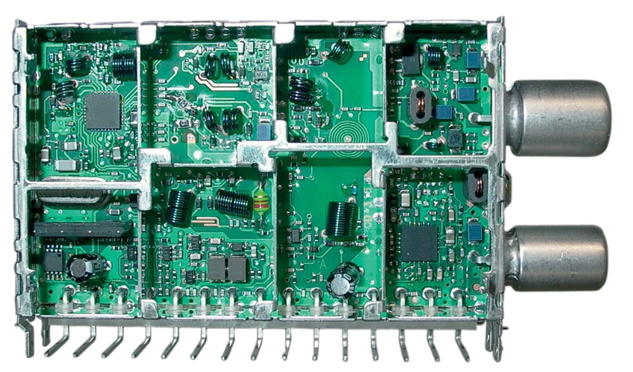
This was most likely a prototype of the CDM1300-Mk3. It shows the modulator IC lower right, but the MOPLL is still mounted horizontally. The final product had the IC rotated 45degrees for bettter soldering. [via Edward Ng]
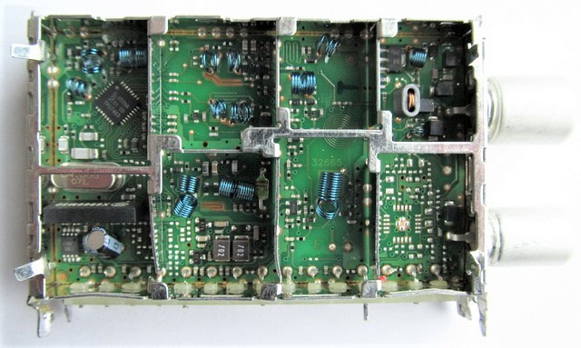
Interior view of the production CD1300-MK3. This one, a CD1316L/IH-3, did not survive being de-soldered and opened unscathed, but shows the leadless HVQFN package of the MOPLL, and below it crystal, SAW filter and the LA7795 IC. Upper right the loop-through LNA, below that the unused footprint of the modulator.
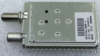
One of the most used versions of the CD1300-Mk3: the CD1316L/GIHP-3, where the G referred to the long F input connector, the I to the IEC output connector, H for horizontal and P for DC power on the RF input.
|
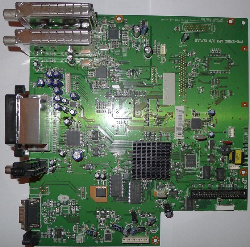
The Humax IPVR 9200C with a Twin Tuner arrangement, upper left. It also used two TDA10023 NXP cable channel decoders. [Maarten Bakker]
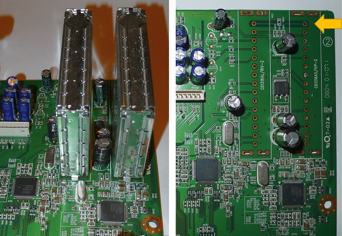
Close-up of the Twin Tuners, mounted on the left, on the right the PCB after removal of the tuners, with at the yellow arrow the connecting RF path. Below the two TDA10023 channel decoders. [Maarten Bakker]
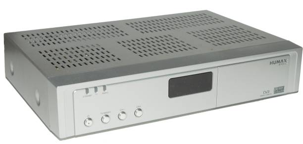
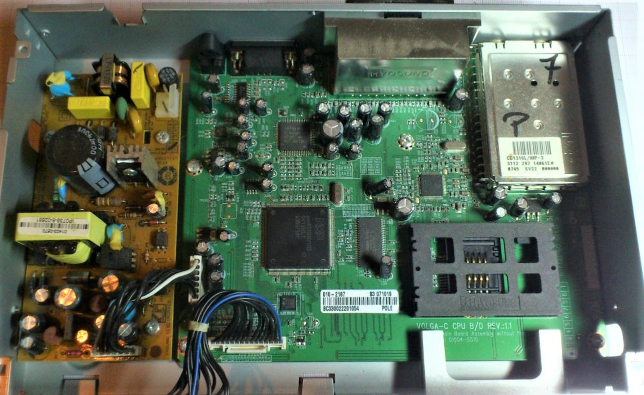
Pictures of CD1300 tuners in their application are rare, because cable modems and STB are typically short-lived products and not deemed very interesting for collecting. But this is the Humax Fox from 2008, containing the CD1316L/IHP-3. Note that the tuner and core IC are now from NXP an no longer Philips.
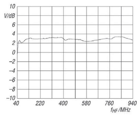
The loop-through of the CD1300L had an impressive flatness over the entire 45-860MHz RF range: 3+/-1dB. [Funkamateur Bauelementeinformation, CD1316L-IHP-3, Feb 2011]
|
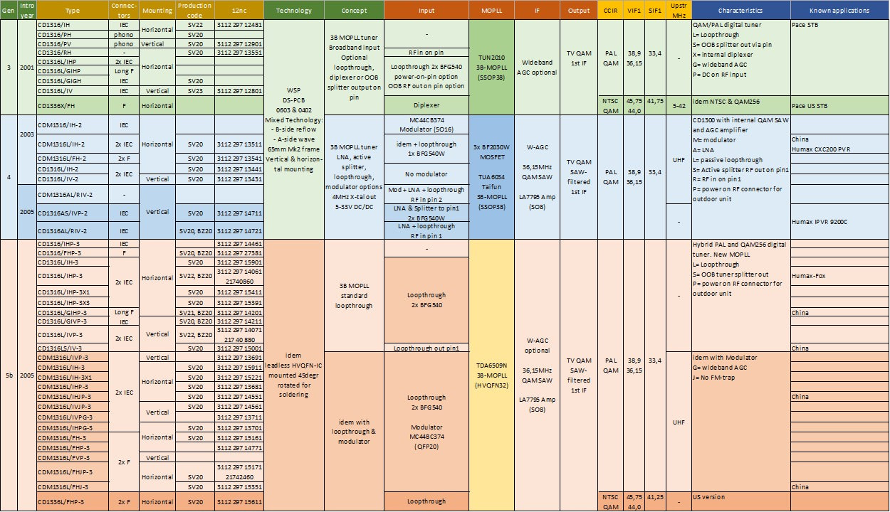
Overview of the three generations Philips CD(M)1300(L) digital cable tuners. Not many customers or application names are known, but were predominantly European and Asian cable modem and STB manufacturers. "China" means that modules are offered by Chinese component vendors. The new style of 12nc-replacing identifiers refers to the Nutune period and means that the type was still sold after 2008.
RF matrix products, 2003-4
From the previous DOCSIS and cable tuner sections it is evident that much of the system complexity and functionality was in the RF function between the single cable input and the many different tuner, upstream transmitter and modulator functions. Their was clearly quite some value in these functions, and the BU Tuners and later BL RF Solutions obviously tried to capture as much of this as possible. As shown, all cable-related tuner modules contained some of the RF frontend functions: loop-through amplifiers, modulators or diplexer filters. But at least for the first two generations of CD1300 this was immediately a main source for diversity. Furthermore, the available space within the tuner module for these functions was limited, as well as the number of connectors that could be used on a tuner module. Some of the RF functions therefore had to use normal wire pins and had to rely on proper PCB board design by the customer, always a tricky thing. Parallel to the tuner modules therefore a second line of product emerged, splitter-modulator modules.
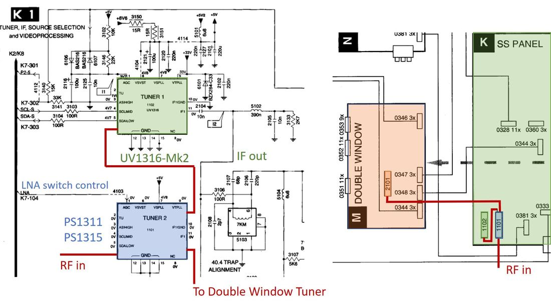
Cut-outs from the service manual circuit diagram (left) and wiring diagram (right) showing the PS1311 and PS1315 as used in the Philips MG3.1 Double Window TVs, like the 28PW9616 and 28PW9525, from 2001 and 2002 respectively. Although in the service documentation only the PS1311 is listed, the LNA switch control line shows that the sets are prepared for the PS1315.
For the origins of Philips splitter modules we have to go back to the standard TV for a moment. The splitter function was introduced in the FQ900 frontends as click-on module and UV1216D splitter-tuner, both to allow Picture-in-Picture (PIP). But around 1996 to 98 the BGTV preferred to use standard tuners whereever possible, and use separate splitter modules for the limited number of real dual-tuner PIP sets. This became the PS1311, an active splitter in a standard UV1300 frame with one input and two phono output connectors. It was introduced starting with the 1999 MG3.1 dual-window high-end chassis from Brugge. At the same time the discussions between the BU Tuners and BGTV architects were already ongoing regarding the by-passable LNA, which the tuner group proposed to improve weak off-air reception. It would take till the UV1356A-Mk3 in the 2001 L01 chassis to get this feature introduced in the tuner, but it was decided to use it as a back-up solution in the MG chassis, implementing it in the splitter module PS1315. It copied the circuit from the UV1356A-Mk2, using the BF1007 MOSFET as by-pass switch. The last application of these splitter modules was in the EM chassis, on the same platform of the MG3, that used an I2C-controlled version of the LNA bypass. Hereafter, in TV sets, splittters would again be integrated into tuners, like the UV1316T-Mk3 and UV1318ST-Mk3.
|
Based on the above experience with TV splitter modules, a first step was made towards QAM/CATV-specific splitter modules. Here the BL RF Solutions developed the view of the "RF Matrix", based on the many different RF input paths that were possible in (EURO)DOCSIS modems and STBs. Based on this a number of building blocks could be combined to provide application or customer specific solutions:
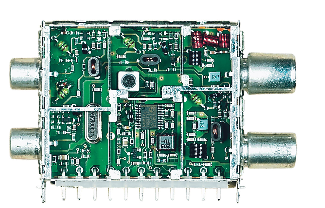
The Philips PM1314. Upper right is the diplexer filter with left of it centrally the input LNA, with in the leftmost section the two output amplifiers. Centrally the TDA8722 modulator and lower right the loop-through amplifier and modulator coupler. [via Darko Jancin]
|
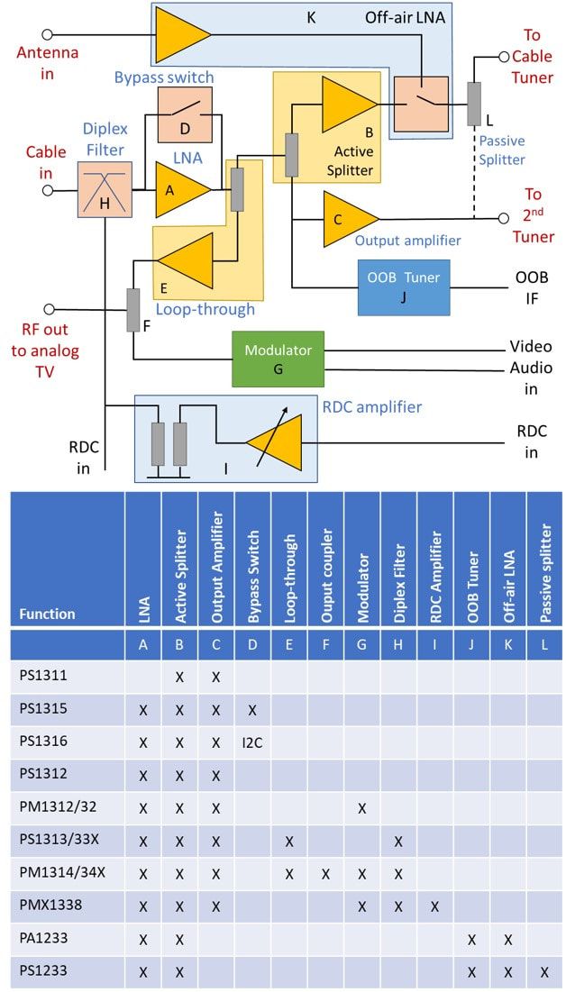
Overview of the input RF matrix functions, and below it the mapping matrix for the different Philips modules.
|
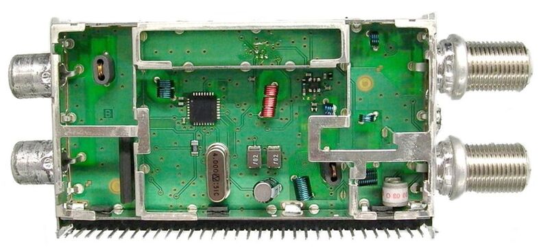
The only available picture of the Philips PS1233, with centrally the TDA6509 MOPLL. [via Edward Ng]
The final product in the range of splitters was an interesting one, the PA/PS1233. This was targeted at the STB application, with both cable and terrestrial inputs. The module was thus essentially a two-stage splitter, first splitting the cable input into the main and OOB tuner paths, and then secondly, after selecting either the cable or off-air input, a passive splitter to two tuners. However, most interestingly was the integration of the OOB tuner within this module. Although only a very limited 70-130MHz frequency band needed covering, nevertheless a standard TDA6509 3B-MOPLL IC was used. Formally it therefore was again a tuner-splitter module, although, in contrast to the standard loopthrough-tuner, now with the tuner the secondary function. For reasons not yet fully clear the PS1200 used a large TC/CU1200-style frame with the external row of 32 pins.
A last product worth mentioning here, also for lack of a better place, is the stand-alone OOB - or Forward Data Channel (FDC) in DOCSIS terminology - tuner, based on the same concept as used in the PS1233. This product is an even bigger mystery, since it is mentioned in the RF Solutions product leaflet, a preliminary data sheet is known, and it is mentioned as being used in the 2005 L05.1 ATSC chassis for the US market. But other than that, traces are minimal.
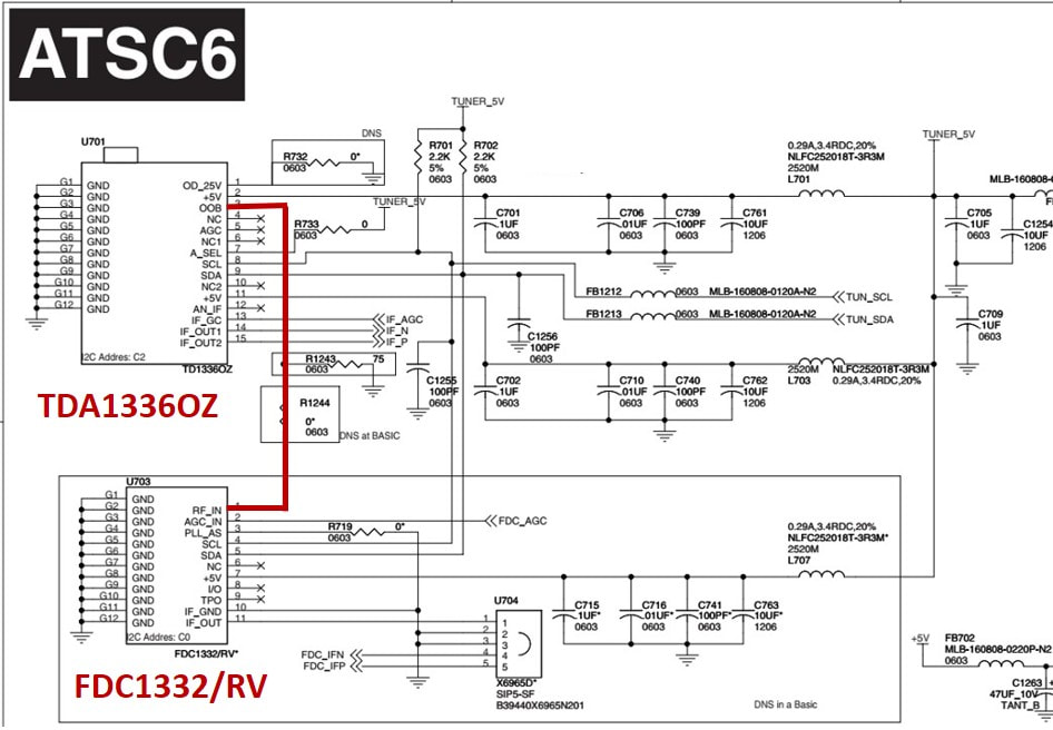
Front end section of the ATSC bolt-on card in the L05.1 chassis and its 28, 30 and 32PW9100 16:9 sets. Note that the RF loop-through from the primary TD1336OZ tuner to the FDC1332 FDC tuner is via a PCB RF trace, indicated in red. [Philips L05.1 Service Manual, 2005]
|
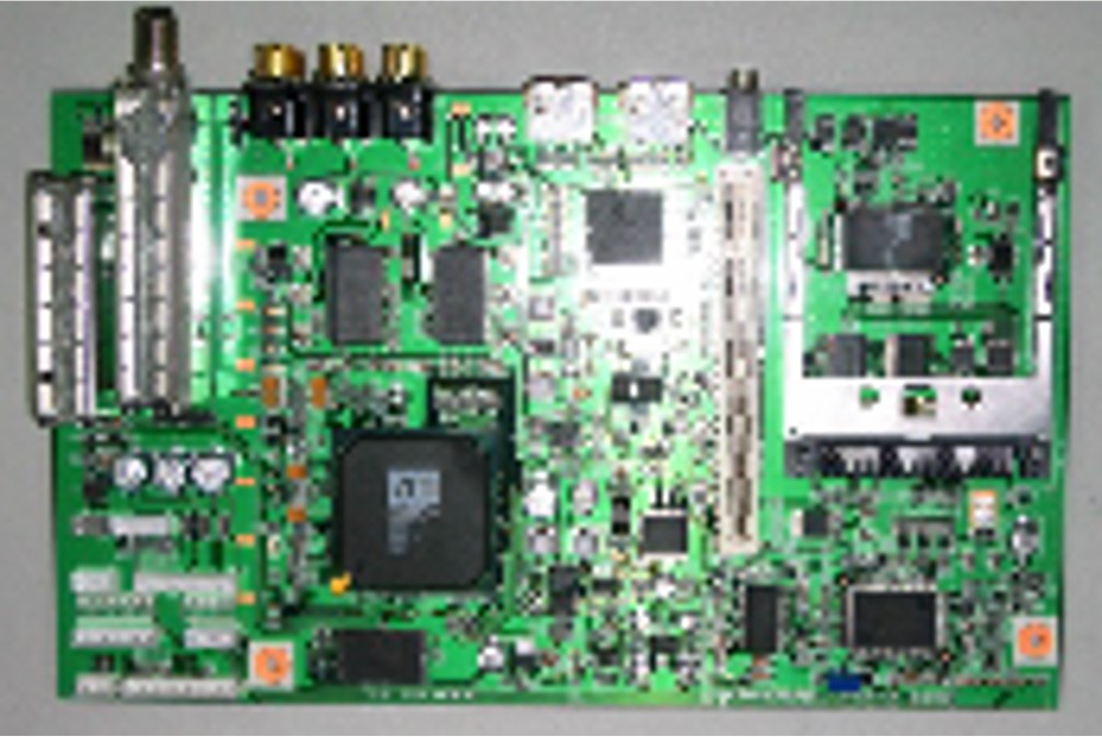
A very bad, but unique and therefore included picture, of the FDC1332 (far left) and TD1336OZ (to the right of it) on a Digital Stream HD DCR-TV add on board.
|
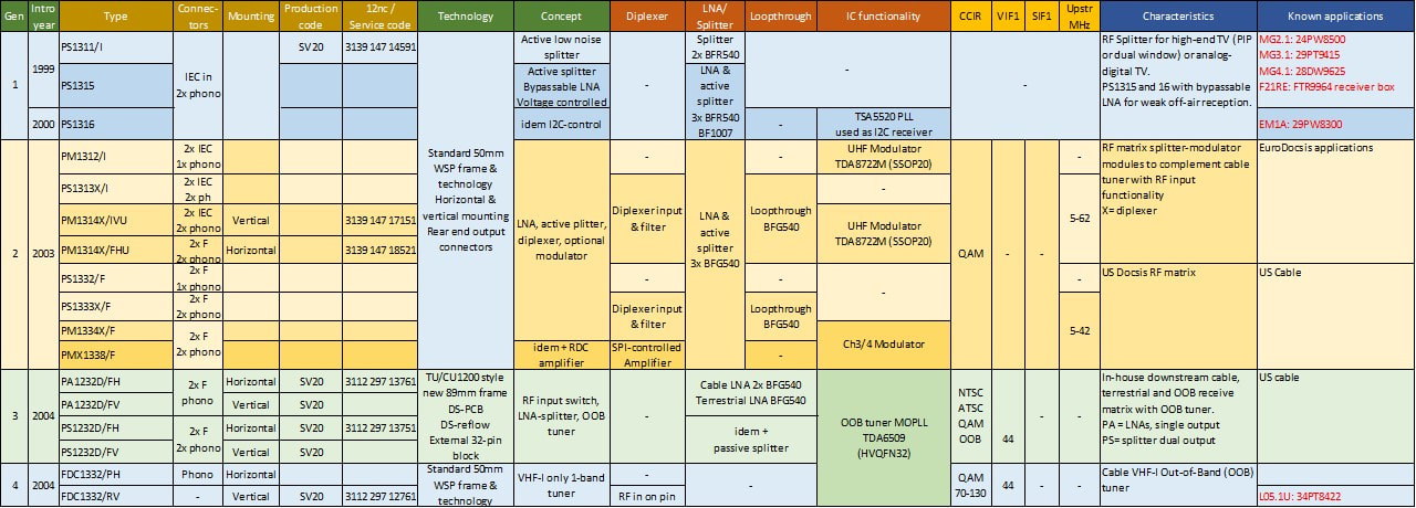
Overview of the Philips splitter and modulator modules for TV and QAM cable boxes.
CU1200 Cable-NIM, 2004
After the SU1200 satellite-NIM and TU(V)1200 terrestrial NIM it is no surprise that also for cable applications a NIM was developed. The CU1200 was obviously closest to the TU1200, and started based on the same TUA6034 MOPLL. The channel decoder was the Philips Semiconductors TDA10021, which covered all QAM formats specified under DVB-C up to 256-QAM. Because all cable RF input diversity was covered by the RF Matrix modules, the NIMs only had the loop-through functionality. A full family of CU(L)1216 modules was launched in 2004, but probably did not generate high sales initially. Whereas the TD1300 targeted cable modems and STBs, the CU1216 was aimed at the PC Multimedia segment, which took some time to appreciate NIMs, especially cable-specific.
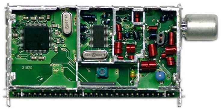
The first generation Philips cable-NIM, the CU1216/IH. Centrally the Infineon TUA6034 MOPLL, far left the Philips semiconductors TDA10021 QAM channel decoder.
Again, just like the TU1216, intermediate system upgrades were made related to the key components, and like for the TU1216 the transfers were a bit fuzzy. Rather quickly after the inital CU1216-Mk1 release the conversion to a Mk2 started, switching to the Philips TDA6509 MOPLL, the Sanyo LA7996 IF VGA, and introducing the Passive Loop-Through (PLT) based on the new Philips BF1008 MOSFET. This became the CU1216LS-Mk2, the S referring to the PLT function. However, although the data sheet was issued, it is doubtful this Mk2 was ever formally released since it was almost immediately superceded by the Mk3, linked to the change to the TDA10023 channel decoder. This IC, which was otherwise pin-compatible with the TDA10021 but next to DVB-C now also covered DOCSIS (strangely enough referred to under the old name MCNS in the data sheets). The main reason for switching to the new IC was most likely a lower price due to a CMOS node migration, and not the DOCSIS functionality. Nevertheless a unique single CU1236/AGGH-3 was made for the US DOCSIS application.
Although it had taken a while, the CU1216L-Mk3 now became a very successful product, used both on PCI-cards as well as cable modems for a number of years. The German company Dreambox, as already mentioned in the TU1216 section, was an ardent supporter of the NIM concept, using in different combinations SU, TU and CU1200 modules on the same mother board to offer satellite, off-air and cable boxes. Another, also German, company was Reel-Multimedia with its Reelbox concept, similar to Dreambox. (In contrast to Dreambox, Reelbox only used a Philips NIM for cable and off-air, relying on Japanese suppliers for satellite. After being quite successful for a while it went bankrupt in 2013). The CU1216-Mk3 was one of the products running when the bussiness was sold to Nutune, and continued - under different names - till at least 2009. 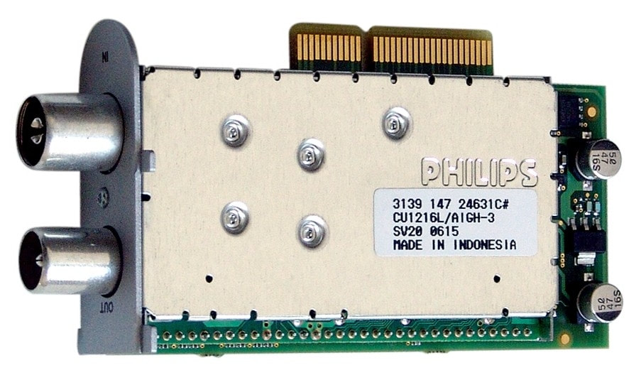
The same Philips CU1216L/AIGH-3 as shown opened, now on its Dreambox tuner card.
|
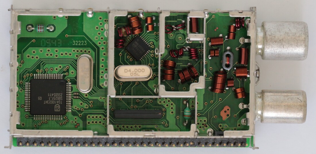
B-side of the CU1216L/AIGH-Mk3 cable NIM. Left the TDA10023 channel decoder, centrally the 45degrees rotated TDA6509. Below it the 4MHz crystal and at the bottom the SAW filter. Also note the mounting screw hole added between the RF connectors. [Henk van der Wijst collection]
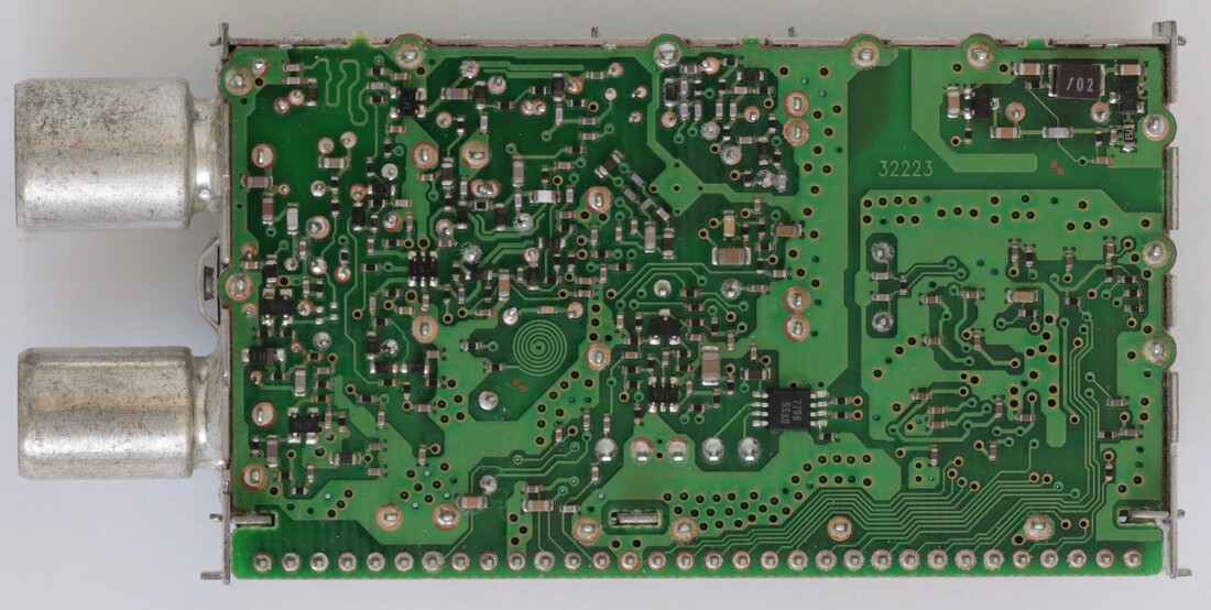
A-side of the Philips CU1216L/AIGH-3. Far left the loop-through function, next to it the single and dual MOSFETs, lower right the LA7996 IF VGA. In the upper right corner the DC/DC-converter. [Henk van der Wijst collection]
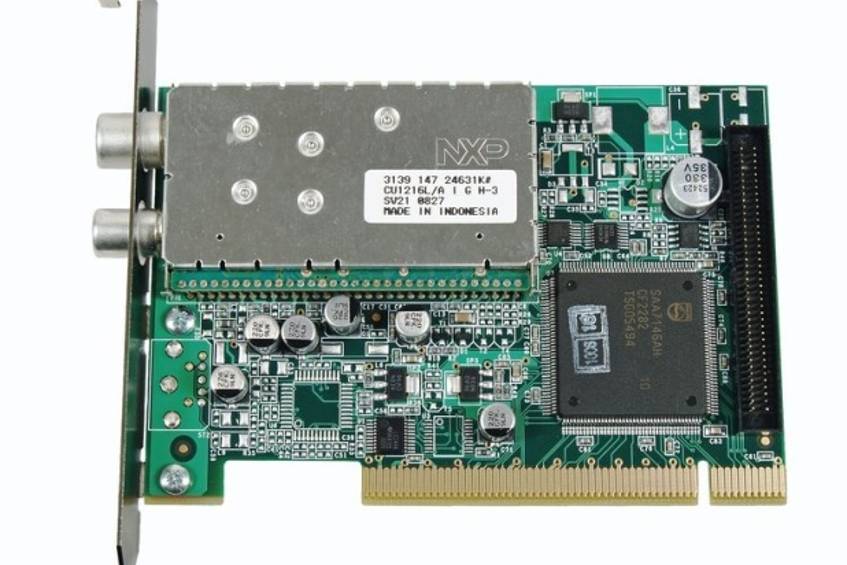
Again the same module, which was absolutely the main runner of the CU1200 family, on a KNC-One PCI card. Right of it the large Philips SAA7146 MPEG-to-PCI bridge IC.
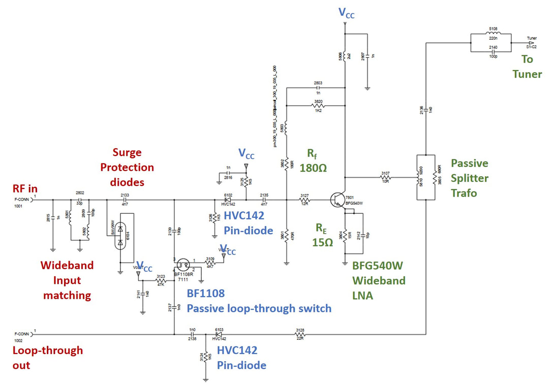
Input circuit of the CU1216LS-Mk3. Red is the input circuit, blue the Passive Loop-Through (PLT) and green the LNA and loop-through splitter. When Vcc becomes zero the two serial pin diodes switch off, while the BF1108 MOSFET closes. [via Thomas Fenkes]
|
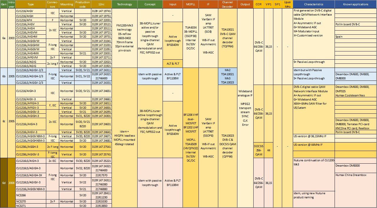
Overview of the Philips family of CU(L)1200 digital cable Network Interface Modules (NIM). The cluster at the bottom are the products continued under different name or serial ID by Nutune after 2008. Note that all modules were produced in Batam (SV20-22) but that some main runners were also transferred to Suzhou (BZ20).
Philips TV developments 2000-2008: flat screens, HDTV and digital standards
So far, all developments discussed in this chapter were related to the two new consumer applications: Set Top Boxes (although mostly not bought or owned by the consumer, but rented out by the operator as part of the service subscription), and the PC Multimedia PCI-interface cards. In the meantime VCR had become obsolescent, replaced by DVD. But DVD was based on digital standards, obtaining its video source signal from other digital sources, and most DVD players consequently did not contain a tuner. So, what about the oldest video appliance, the good old television set? Up to almost exactly the year 2000 life in the world of television was hectic, with lots of competition and price pressure, but at the same time also predictable: displays were based on the Cathode Ray Tube (CRT), which became step-wise larger, flatter, 16:9 reactangular but also excessively heavy and large. Almost each of the developments mentioned required strengthening and thickening of the CRT glass to provide mechanical strength and counter the internal vacuum. All standards were still analogue, after the failure of D2MAC (which was still conceptually analogue, but with more digital processing), and digital standards were restricted to the STB, which then fed analogue signals to the TV. However, almost around the same time, i.e. the turn of the century, three developments kicked in that would ultimately change the entire TV set world and its main players:
- new display technologies
- higher resolution, moving to High Defintion TV (HDTV)
- digital encoding standards for higher transmission capacity.
|
The size and weight of displays had obviously been a topic that received quite some attention. Developments of technologies that supported much thinner (usually referred to as flatter) displays started as early as 1965 when the plasma display was invented. The plasma display is based on the same concept as the fluorescent lamp, with tiny glass cells filled with noble gas (mostly neon) plus a tiny addition of e.g. mercury. When a high electric field is put across such a cell a plasma will be generated that emits ultra-violet radiation, which is finally transferred into red, green or blue by phosphors applied on each cell window.One pixel thus contains three of these cells, whch are addressed individually in a matrix through column and row drivers. Plasma screens have the advantage of a very wide range of colours and a very deep black, so high contrast. Plasma screens are, however, heavy due to large amounts of glass to support the vacuum. It took 20 years of development until Fujitsu-Siemens brought out a first plasma TV in 1995. Although the TV was clearly much flatter, image performance was still well below CRT. Plasma became a primarily Japanese driven technology, with Fujitsu, Sharp and Panasonic the main players.
Philips, by its very nature, was of course developing its own technology, based on a NatLab Research invention. It used the revolutionary concept of hopping electrones in a very thin glass wafer construction. Because the electrones moved through channels, vertical support structures could be used, allowing very thin glass. It was called Zeus and declared one of the presidential Top Projects when Jan Timmer became president in 1991, and kept highly secret. A large team was working on it, both in Research and the PD Components, and around 1995 28" prototypes were ready. But to industrialize it, major investments were required, and Philips finally started probing for partners in Japan. However, these had all chosen for the plasma technology by then, and were eager not to be strangled by yet another of the greedy Philips technology licensing contracts like the CD or DVD. Philips was on its own, even after the technology was published in 1996. May 1997, after an off-site meeting with the Philips management, it was decided that Zeus would not be industrialized. |
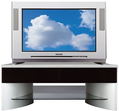
A state-of-the-art high-end Philips TV set from 2003: the 32PW9788 based on the EM6E chassis. It featured a real-flat 16:9 wide screen CRT with Scan Velocity Modulation (SCAVEM), two-tuner Picture-in-Picture (PIP), PAL+ and 100Hz picture improvement, comb filter for better colour separation and Dolby ProLogic2 sound. It would turn out to be the last real high-end CRT platform developed by Philips.
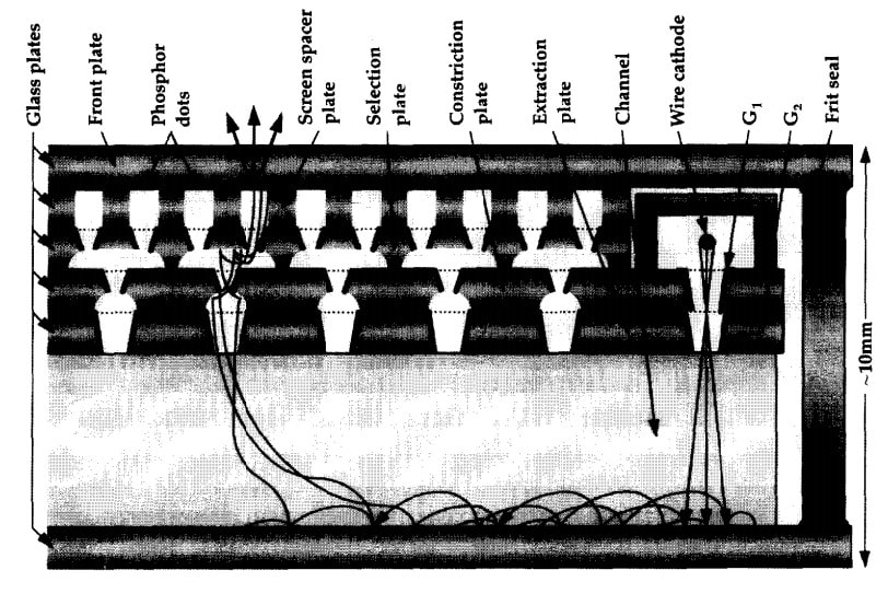
The principle of the Philips Zeus flat display, showing the hopping electrons. [G. van Gorkum, "Introduction to Zeus displays", Philips Journal of Research, Vol. 50, No. 3/4, 1996]
|
Liquid Crystal display technology cdevelopment also started back in the 1970s, and took 20 years to reach a first practical level of applicability during the late 1980s, in watches and later small portable televisions. These developments mainly took place in Japan, at the time the place where miniaturization was pushed most consistently. LCD performance for larger screens, especially dynamic pictures, was far below the requirements for TV, and towards the end of the 1990s the first 14", 15" and 17" LCD screens were used for computer monitors, handling more static images. But LCDs, although small and monochrome, were of course the basic display technology for the emerging mobile phones. Although initial LCD developments were concentrated in Japan, in the mid 1990s the centre of gravity started moving towards Korea, with both Samsung and LG becoming the leading players. But Philips had also joined the LCD battle, with at least internally the ambition to become the number one LCD player globally, as always based on a NatLab claim they had a unique technology differentiator. The empty fab of the former MEGA SRAM development project on the NatLab premises was converted to an LCD fab around 1992, and later a joint venture was made with the Japanese company Hosiden, with Philips investing 200M$ and step-wise increasing its JV share to 80%. In 1998 a new business group Flat Display Systems was created within the PD Components, led by Matt Medeiros from Silicon Valley San José, who we've seen earlier.
|
LCD is fundamentally different technology from plasma, which is active and generates its own light. LCD is a transmissive technology, where the light from a constantly active backlight - in the beginning typically fluerescent lights - is passed through or not. This on-off mechanism is achieved with liquid crystals that are forced to rotate under electric filed control with electrodes deposited on the enclosing glass plates. LCD therefore had a few major challenges: low contrast because there was always some backlight light passing through and attenuation was not maximal when in black mode; low brightness because the on-glass electrodes absorbed part of the light; and a low viewing angle due to the light path using optical polarization filters. It took many years to optimise all these parameters to acceptable levels. LCD developments were, however, not just a continuous innovation battle to come to thinner, brighter and better displays, but especially also an enormous cost drive to larger and cheaper panels. This was a typical economy of scale game: the bigger the glass plates used to make LCD panels and the bigger the fab capacity, the cheaper the price per panel, obviously. So, between 1990 and 2000 the typical panel size in production increased from 20x30cm (GEN1) to 68x88cm (GEN4) while by 2007 the GEN8 panel size had become 2x2,5m.
|
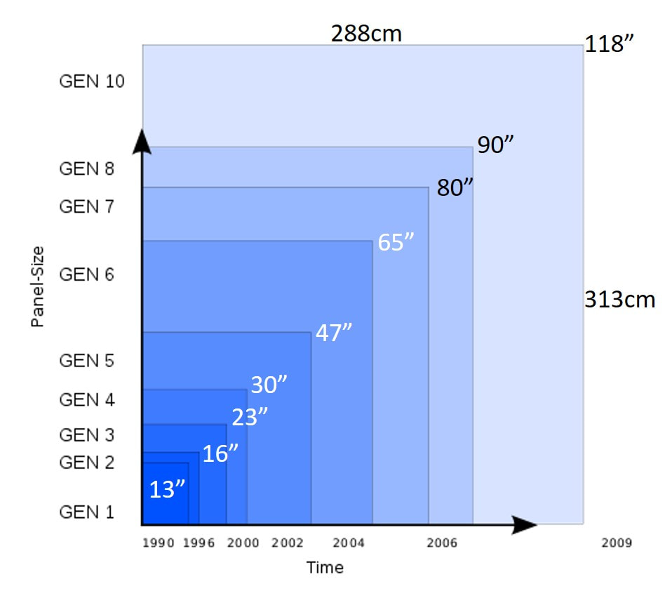
The growth of LCD glass panel size in the two decades from 1990 to 2010. The diagonal size in inches is mentioned as reference for the TV display size. [Modified from Wikipedia]
|
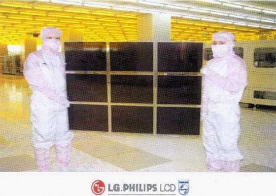
The first Gen5 panel from the LG.Philips Gumi fab, Korea, measuring 110x125cm. The panel is used to produce nine 30x40cm 14" screens. [Liquid Gold, Joseph Castellano, World Scientific Publishing, 2005]
|
Because of the abundent money available to the Korean chaebols, Samsung and LG were making the biggest steps in these developments, constantly building new and bigger factories, while companies like Philips and Sharp, with much more difficult access to credit given their company debt and national economies, had increasingly troubles to keep up this battle. Then, not inconvenient to Philips, the 1998 Asian crisis developed, bringing the Korean companies in acute financial trouble, which Philips used to acquire a relatively cheap share of 50% in the LG active matrix LCD business. The JV, signed in September 1999, became LG.Philips LCD, Philips subsequently investing 1,6Bio$ into it, and becoming the number 1 LCD supplier globally. The same year the Eindhoven fab was closed - the building was destroyed a few years later - all activities being concentrated in Japan (large displays) or Heerlen (Netherlands, monochrome mobile displays). Developments continued aggressively, reaching the critical panel size of 47" (GEN5) in 2002 and 65" (GEN6) in 2004. This brought LCD on par with plasma displays in terms of size, while the economy of scale led to a spectacular price reduction. By 2003 LCD and plasma were ready for entering the TV display arena.
|
Video compression, enhancement and definition
From the very start television has been driven by the ambition of higher defintion images; the 405-line Britsch and 819-line French standards from the mid 1940s were both presented as high defintion! Over the following decades CRT display sizes steadily grew while the depth reduced, although limited by physics, especially the thickness of the glass and the ability to control the scanning of the electron beam. Colour had been a major improvement, and during the early nineties Philips introduced real flat displays with rectangular windows. For images larger than 29", in practice the limit of the CRT size, there was always (rear) projection television. However, there was a fundamental limitation for increasing the picture size much further, simply due to the resolution of the transmitted signal. From the 1980s therefore work on "real" High Defintion Television (HDTV) started. In Europe this led to the D2MAC and HDMAC standards, in Japan the MUSE system was developed, both mainly using satellite for broadcasting. Although neither of these became a big success, they were important steps on the way to real HDTV, which had to wait for digital technologies.
|
A first step towards much improved picture quality was the 100Hz concept, largely developed and introduced by Philips based on work in the NatLab Television group. Using the emerging digital CMOS technologies this concept used line memories (the entire sampled content of a 64us long signal representing one horizontal line in an image) to add or mix the content of different lines. Using adjacent lines from the two classical half frames to interpolate the additional lines. By doubling both the line and frame scanning speeds, within the same time (64us) of one classical line now two lines could be projected on the screen, the second one essentially filling the open space of the interlaced line that would normally come half a frame later. In other words, instead of an interlaced 50Hz image (resulting in a real picture frequency of 25Hz for PAL, NTSC of course at 30Hz) the result was two quasi progressive scan 100Hz images. When combined with advanced digital noise filtering, almost flicker-free images were produced with the perception (only!) of increased resolution. The 100Hz concept for PAL uses both doubling of the line and frame frequencies and was called "Digital Scan" by Philips. For NTSC, at the higher 60Hz frame rate, only the line frequency required doubling and was called "Progressive Scan". It is clear that to support 100Hz the bandwidth of all related video processing functions required doubling of the bandwidth too. However, this could only be done after demodulation of the received TV signal, because the RF channel up to and including the tuner remained standardized at 6, 7 or 8MHz, depending upon the transmission standard used.
|
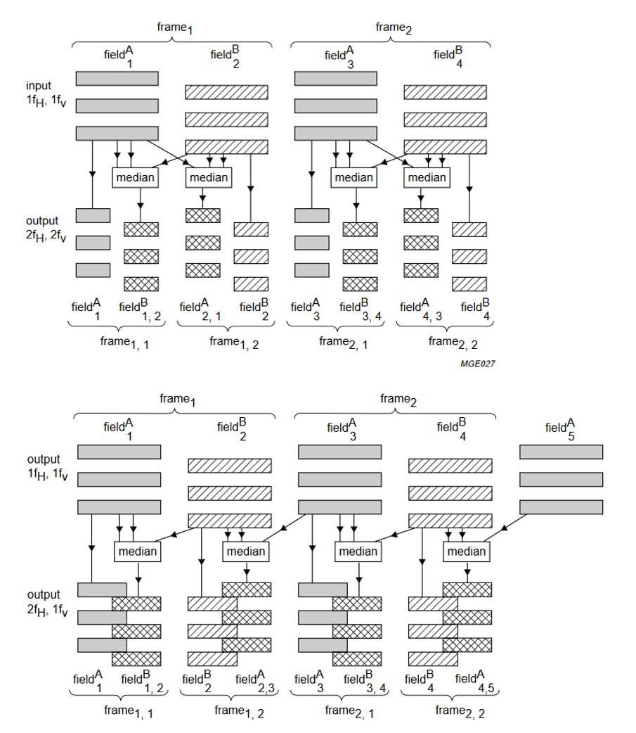
The concept of PAL Digital Scan (top) and NTSC Progressive Scan (bottom) as implemented in the Philips PROZONIC IC, introduced in the 1995 GFL high-end TV platform. [Philips Semiconductors SAA4990 Service Manual, 1996]
|
An essential element of HDTV is therefore video encoding, to reduce the bitrate of a raw digitized TV signal to a rate that fits, after proper modulation, in a standard TV channel bandwidth. MPEG2, issued in 1995 and standardized by the ITU as H.262 is the best known and most widely used system, based on the Discrete Cosine Transfer (DCT). In parallel the ITU also standardized the picture aspect ratio for HDTV as 16:9 and the associated line rates. This resulted in the following standard parameters that would be the basis for the migration to HDTV (notation is horizontal number of pixels x vertical number of pixels i(nterlaced) or p(rogressive) /frame rate ):
- Standard Definition (SD) 720x480i/25
- High Definition (HD) Ready 1280x720i/25
- Full HD interlaced 1920x1080i/25
- Full HD progressive scan 1920x1080p/25
Because this resolution results in 2,1Mio pixels on the screen, it is also referred to as 2K TV.
- XGA 1024x768p/25 (4:3)
- WXGA 1366x768p/25 (16:9)
Philips Semiconductors: SoC integration, 1995-2008
Before diving into the actual chassis developments of Philips it is essential to have a closer look at Philips Semiconductors first. As one of the oldest still surviving semiconductor players, it had a long and leading position and analogue and mixed-signal ICs, often based on the applications where Philips was active: Consumer Electronics. In terms of volume it was towards the 1990s around the number 8 to 10 position globally, at the same level as French STM and German Siemens/Infineon. Positions changed every year due to the ongoing merger and acquisition actions in the semi industry. Where Philips technology was traditionally based on analogue-centric bipolar technologies, CMOS was steadily growing in capabilities. Up to the 150um node developments had always been done in-house, but these became increasingly costly and since 1993 Philips teamed up with ST Microelectronics in the Crolles fab (Grenoble, France) to develop CMOS technology, which was then produced in one of the Philips fabs in Nijmegen, Hamburg, Caen, Alberquerque and, since 1996, former IBM Böblingen fab in Germany. In 1998 the 0,25um node was released, called C50 internally, followed in 2000 by 180nm (C18) which was to become a major node for analogue-mixed-signal design for many years.
|
Around 1995 it became clear to the Philips Semiconductors management that with every new CMOS node the way of working differed more and more from the classical analogue design. Digital CMOS design required more and different simulation tools, increasingly expensive place and route and verification tools, and to speed up design more and more standard functional blocks (so-called IP blocks). A campaign was thus launched for "Going Digital", mainly driven by the Semiconductors CTO Theo Claasen. This was a costly excercise, not only through the Crolles alliance that cost a few hundred Mio per year, but also through the build up of a massive Central Research & Development (CR&D) organisation, eventually becoming an organisation of close to 3000 people. For at least ten years Semiconductors would invest around 1BioHfl per year into these digital technologies. To support all this, and to create the right "focus", the downside was the official doctrine that only digital had the future and analogue was doomed. Investments in analogue BLs and technologies were much reduced, despite the fact that these delivered some 80% of the turn-over and all profit. One example was the very efficient PCAL appplication labs organisation, with labs in Eindhoven (PCALE), Hamburg (PCALH) and Southampton (PCALS), and which contributed a lot to the application support on system level. These now became System Labs in 1997, focussing on digital system support, where almost all work on analogue applications was forbidden. (This occasionally created quite some panic, e.g. when the Hamburg Car Radio business, the market leader in this segment, found out that its entire design team had been forced to leave Philips; they had to be hired back at twice the cost for ten years).
To further boost the digital switch over, the US company VLSI was acquired in 1999, although this was a far from obvious match. Whereas Philips concentrated on standard products (transistors and diodes, logic, microcontrollers) and application specific products (ASSPs, which includes all tuner-related Semiconductor ICs discussed so far), VLSI primarily made digital ASICs, i.e. customer specific products that were designed on request. They therefore had a completely different design centre set-up, with many small centres close to (US) customers, in contrast to the large centralized centres of Philips. Over the following few years only few of the original VLSI centres survived. Furthermore there was a large portfolio overlap, which took years to integrate. (For at least another 8 years the Semiconductors mobile phone business supported two complete but entirely different platforms, one Philips and one VLSI, not able to decide on dropping either one of them). But there were not only downsides, since VLSI brought in a modern 120nm CMOS technology in its San Antonio fab, which gave a boost to the internal CMOS portfolio. And we already mentioned the good DVB channel decoder portfolio of VLSI.
|
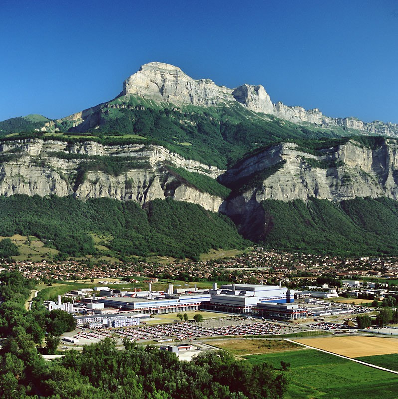
The Crolles fab near Grenoble, the French Alps in the background, where Philips and ST, later also with Motorola/Freescale and TSMC, developed advanced CMOS technology. On the left the Crolles1 fab, right of it the larger Crolles2 building.
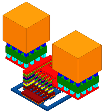
Conceptual picture of the metal stack in an advanced 65nm CMOS technology. The lowest brown layer contacts the transistors, on top of it are another 4 metal layers, while the red layer is Metal layer 6 (M6). M7 and M8 on top are thicker to allow the aggregated supply currents without electromigration problems. [Researchgate.net]
|
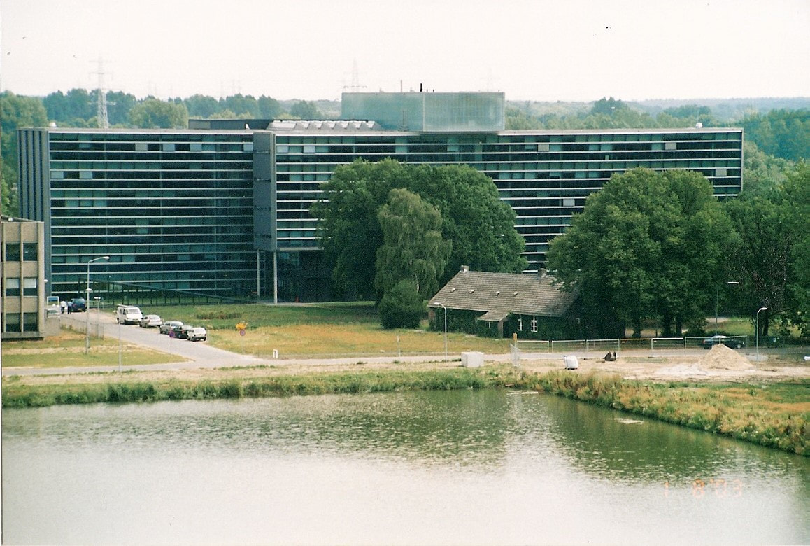
The new Philips Semiconductors headquarter on the Eindhoven High Tech Campus, HTC60. In front the surviving farm, which is used for celebrations and drinks. On the left the edge of the patent office that was soon to be demolished. [Pieter Hooijmans]
|
But every next step in CMOS development became more expensive. Beyond 180nm the step from 8" (200mm) to 12" (300mm) wafer production was required, as well the development of new Copper back-end technology. This required a major investment in a new Crolles2 fab, to which Philips still contributed. To share the costs Freescale, the former Motorola Semiconductors division, joined the team, while a relation with number one foundry TSMC from Taiwan was established. In Crolles2 the 90nm and 65nm nodes were developed. However, the costs were very high and the differentiation against the benchmark TSMC technologies minimal (and TSMC was usually two years ahead too). So in 2007 Philips (by then NXP) left the Crolles alliance, from then on relying entirely on foundries for its CMOS technology.
|
From around 1995, with the start of "Going Digital", the organisation was built around three application Business Units: Consumer, Telecom Terminals and Discrete Semiconductors. After the VLSI integration these businesses were as follows in the year 2000:
- BU Consumer (HQ Eindhoven) 2100Mio€
BL Video, covering all analogue and digital TV ICs, with the one-chip TV the main product
BL Digital Media, which included the remains of the STB IC business (which Philips was exiting after their last platform had been too late and a failure, ST now being the market leader in this segment) but also the Product Line Tuners (MO, MOPLL)
BL Infotainment Systems, mainly Car Radio and Audio - BU Telecom Terminals (HQ Zürich, Switserland) 1400Mio€
All mobile phone, cordless phone, wireless connectivity and display drivers business
At this time Philips was the number 1 globally in RF ICs for telecom, serving both Philips and Ericsson - BU Transistors and Diodes (HQ Hamburg) 1360Mio€
This included the BL RF in Nijmegen, including the tuner MOSFET & varicaps - BU Multi-Market (HQ San José) 900Mio€
Logic, interface products and microcontrollers - BU Emerging Businesses (HQ San José) 750Mio€
This included the cable modem developments.
- Communications (HQ Eindhoven under Mario Rivas, who joined April 2001 coming from Motorola),
1,6Bio€ IC plus 1,1Bio€ MDS - Consumer (HQ Eindhoven under Leon Husson) 1,6Bio€
- Multi Market Solutions (HQ Eindhoven under Hein van der Zeeuw) 1,1Bio€
|
One specific development for TV and Consumer applications needs explanation: the Trimedia processor. This was a Very Long Instruction Word (VLIW) core specifically suited for streaming video processing, developed at Philips Research and launched in 1996. In 2000, after integration with VLSI, the Trimedia activities were spun out, based in San José, to become an independent IP vendor, offering the Trimedia as competitor to Intel cores. The new company developed a new 64-bit core, but went almost bankrupt during the dot-com crises, only to be rescued by Philips when they were re-absorbed into the company in 2003. It then became internal religion within the Consumer cluster, where for a while it was expected that all products had to use the Trimedia core, whether needed or not. Since religion in technology is always counter-productive this strategy naturally failed, although the TM3270 64-bit 350MHz core in 90nm was succesfully used in the PNX8550 and PNX8541 TV platforms and their successors. This focus on Trimedia and the associated applications was reflected in the new name Nexperia that was from now on used for all media processing ICs, and were coded PNX.
|
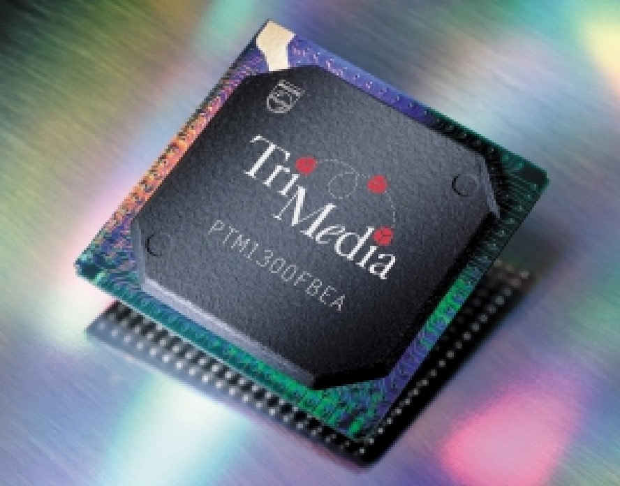
The Philips PTM1300 Trimedia processor from 1999. [TM1300 Programmable Media Processor leaflet, 1999]
|
Philips TV platforms, 2000-2008
Before getting back to the TV Tuners it is essential to understand the developments within the Business Group TV, and the concept of the many different platforms. The trend that was happening at the tuner level was repeated in the TV: the ever increasing functional integration and importance of the ICs in the total TV system meant that there was less and less functionality outside the ICs, and that the system architectural ownership slowly but steadily moved to the semiconductor side. So, unless the system integrator had a good relation with the IC supplier and was able to drive the joint IC defintion discussions in an early phase, he was destined to use whatever IC was available. This was especially true for BGTV, which had to deal with very rapid integration. On top of that they were struggling with the fundamental challenges already discussed, the introduction of flat displays (but which?), digital television (but how?) and HDTV (but when?). It goes too far to discuss every single chassis, but using below overview the main trends will be highlighted.
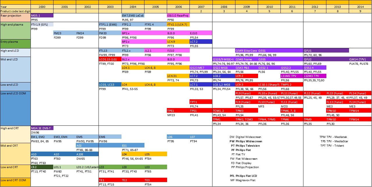
Overview of the Philips TV chassis between 2000 and 2014. Different colours refer to the underlying IC platform. Red are non-Philips chassis. The codes below a chassis are the part of the product name determining the TV set positioning and features, ranging from (effectively) 30 for the most low end sets to 99 to the top of the line models. From 2006 the last digit of the product name identifies the year of release, which makes it easy. So until 2006 the name of a standard 21" mid-end TV could be like 21PT65xy where xy identified a specific model. From 2007 all (now universally flat) TVs would be like 42PFL56xY with 42 the screen diameter in inches, PFL for Philips Flat TV, 56 the feature indicator, x the model identifier and Y the last digit of the year of release.
|
By the turn of the century the situation with repect to the BGTV platform strategy was still as it had been for many years: a low end platform that was updated bi-yearly (L9 in 1999, L01 in 2001, L03 in 2003) using the Semiconductors 1-chip TV ICs (the TDA88xx, TDA95xx and TDA93xx families, respectively). In the years between a mid-end A-chassis was launched, the A10 in 2000 and A02 in 2002. The A10 used the BOCMA (BiMOS One Chip Mid-end Architecture), a 1-chip with slightly more processing power and without the audio, which was standard covered by the ITT MSP34xx Nicam/Dolby digital audio processor. Both the L and A chassis were developed in the Singapore TV development centre. In 2000 the high-end EM-chassis was launched, developed in Brugge as successor to the 1998 MG-chassis. It continued the basic concept for high-end chassis from now on: an IF and input processor (the High-end Input Processor (HIP, TDA9320), very much identical to the 1-chip front end) that delivered YUV signals, followed by the so-called Feature Box (FBX) that could contain multiple signal processing ICs depending upon the features. In the feature box all picture enhancement and processing took place. After processing the HOP TDA9330 output processor generated the RGB signals for the CRT.
|
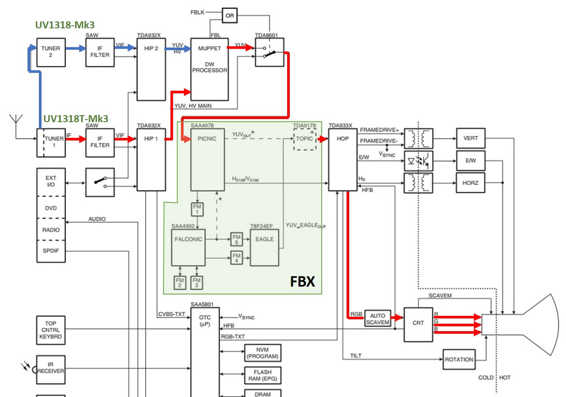
Part of the block diagram of the Philips high-end EM6E chassis including the feature box (FBX), providing the ultimate in analogue CRT performance. In Red the primary signal path in a PIP/Dual Window set, with blue the PIP/DW signal path. For this chassis the high-end UV1318-Mk3 tuners were developed. [Philips EM6E Service Manual, 2003]
|
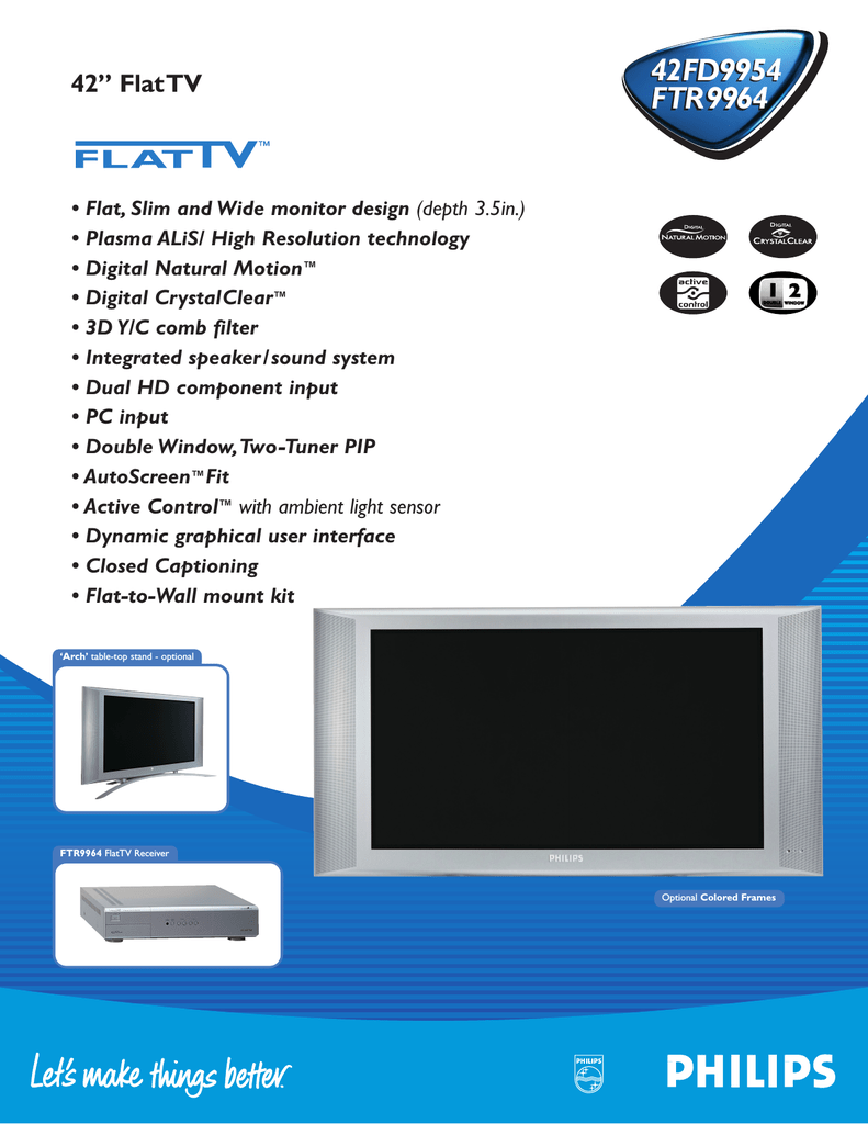
The Philips 42" 42FD9954 plasma display and its FTR9964 E-box shown left. Launched 2003.
|
The FBX could contain one or more of the following ICs:
|
|
Assuming a two year set development, in 2001 the BGTV must have decided to move massively to the new flat displays. However, at this time the jury was still out on the plasma versus LCD comparison, and it was decided to play on both fields. To reduce effort they used where possible the same signal processing platform. Three years earlier a very first series of FLV1 plasma displays was launched, using Sharp displays and the electronics based on the GFL2 chassis. The receiver and primary YUC processing were in a separate so-called E-box, the electronics behind the display were only for signal conversion to the plasma matrix and extensive power management. The same approach was followed for the next generation, the FM24, FM23 and FM33, all using the FTR9964 E-box. They were followed by the FTP1 and the 50" FTP2, where all electronics were now behind the screen, omitting the E-box. In parallel the FTL13 and FTL2 were using the substantially smaller 30" and later 32" LCD panels from LG.Philips Displays. All these chassis were identical to the EM6 upto the Eagle PixelPLUS processor, which was then followed by an FPGA/EPLD for the signal conversion to the display format. New models were released up to 2006, making the entire HIP-PICNIC-PROZONIC-FALCONIC-EAGLE-HOP platform very successful, living for six years. In parallel a mid-end LCD chassis LC03 was launched, based on the A10 BOCMA core, with an additional scaler board for the RGB-to-LCD conversion.
|
The 2004 FTL2.4 chassis 32PF9976, one of he very first wide screen Philips LCD TV sets.
|
The Philips 44PL997(4) LCoS rear projection TV from 2003. It was one of the only four models released with this display technology.
|
One final development based on the EM platform should be mentioned here: Liquid Crystal on Silicon (LCoS). This was a mainly US driven rear projection technology, based on a technology where, as the name says, LCD was deposited on top of a silicon matrix driver IC, allowing very short connections. This IC was integrated in an optical engine with rotating colour wheels for successive illumination of the red, green or blue LCD elements, which acted as reflective mirrors. This concept was developed by the US TV development in Knoxville, with the LCoS chips being produced in the Semiconductors Böblingen fab in southern Germany. In 2003 two 44 and 62" models based on the EM8 and two US 55" models based on the EM5 were released with quite some publicity. However, their life was short because in August the next year Philips announced it would stop LCoS production almost immediately in November 2004, no doubt because they could not support three parallel large screen display technologies. In the slipstream this was also the final blow to the Böblingen fab, which never recovered and was closed in 2007. Yet another internal Philips display technology that did not survive.
|
For the 2004 program two new platforms were developed. The L04 CRT and LC4 LCD chassis were both based on the Hercules TDA1202x third generation Ultimate One Chip (UOC), with the L04 entirely based on the UOC, while the LCD chassis used an additional scaler IC for the RGB-to-LCD conversion. From a Tuners perspective it is interesting to note that the L03 and subsequent low end platforms all used the UR1316 TV and FM radio tuner. These generations, L04 and LC4, also introduced High-Definition Multimedia Interface (HDMI) as a new digitial external source interface. Both the L04 and LC4 were Singapore TV developments.
In parallel to the L04/LC4 an entirely new high end platform was developed in Brugge, the Jaguar, based on a completely new chip set:
In parallel to the L04/LC4 an entirely new high end platform was developed in Brugge, the Jaguar, based on a completely new chip set:
- MPIF (Multi Platform InterFace, Philips PNX3000) containing the video and sound IF demodulators, input selection matrices, A-to-D converters at 27 or 54MHz sample frequency, and I2D serial digital data links. From here on all data processing is purely digital.
- AVIP/COLUMBUS (Audio Video Input Processor & COLour LUMinance Baseband Universal Sub-system, PNX2015) performing video decoding (all analogue standards), all audio NICAM/Dolby decoding, Teletext decoding, 2D/3D comb filtering, HD MPEG decoding, stand-by uPC and finally ITU.656-compatible video encoding as output.
- SPIDER, an EPLD, is a video co-processor connected to the PNX2015, taking care of noise reduction and PixelPLUS picture enhancement.
- VIPER2 PNX8550 Media Processor, based on two Trimedia processors and performing a long list of video enhancement operations like de-interlacing (100Hz), edge detect, anti-flicker, histogram control, LTI/CTI, Black Stretch, horizontal and vertical scaling, skin tone correction, contrast and brightness control. The digital RGB output of the Viper passed through the MOP to the PNX2015 for LVDS encoding, the new interconnect standard to plasma or LCD screens. In the third generation a dedicated LVDS driver IC, the Pacific3, was used.
- Spartan3E MOP (Media Output Processor, another EPLD) for AmbiLight processing, while for pure HD 1080p processing another dedicated EPLD was used, the Cyclone3.
|
The Jaguar platform was a major milestone, being the first really digital Philips TV chassis. After A-to-D conversion in the MPIF all processing was digital, based on flexible processors. The core of the Viper IC, was the TM3270 Trimedia processor, and the IC was made in the latest 90nm technology. This was also the first platform that was from the start defined to handle digital broadcast standards. The Jaguar platform was first released as BP2.1 for plasma and BL2.1 for LCD in the US in 2004, followed the next year by the Jaguar LCD Second Spin JL2.0 in Europe. In 2006 the full-blown Full Jaguar FJ3.0 and Baby Jaguar BJ3.0 came out, which were very successful chassis. In 2007 the Eco Jaguar EJ3.0 was one of the two very last Philips plasma chassis, while in parallel a final archaic rear projection set was released.
|
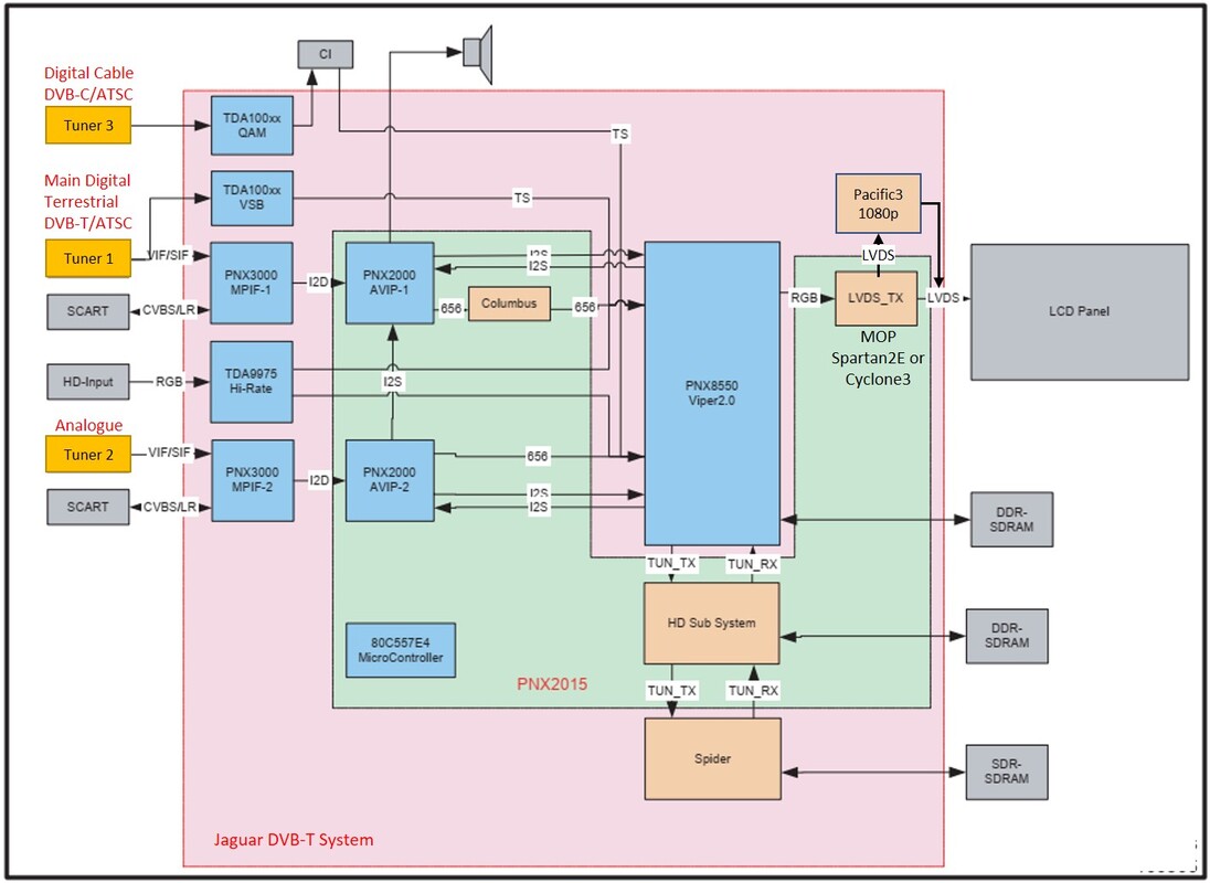
Block diagram of the FJ3.0 Full Jaguar chassis. [Philips FJ3.0E LA Service Manual, 2006]
|
The years 2006 and 2007 were pivotal in the Philips TV business, since a few major developments happened in parallel:
- Although Philips seemed to have been one year ahead, 2007 turned out to be the year when globally LCD came out as the absolute winner during the 2007 Christmas sales. It was almost overnight the end of plasma for most TV suppliers, apart from Sharp and Panasonic that continuedits use for their absolutely high-end segment. Philips had effectively stopped plasma in 2006, in 2007 only releasing the last EJ3.0 and LC7 plasma models.
- It even more so meant the end of CRT TV, after 70 years! In 2006 the last mid end L06 CRT chassis was released, using a non-Philips Trident digital one-chip core. (The 2007 LC07 LCD chassis re-used this core). In 2007 the very last Philips CRT chassis was the L07, using the reliable Hercules one-chip TV core.
- In 2005 Philips had started a close co-operation with the Taiwanese company TPV, by merging it with the Philips low end TV and PC Monitor centre in Taiwan. From that moment onwards low-end LCD TVs were developed and built by TPV. These were the TPS, TPT and TPM chassis depending upon the IC core: TPS is MediaStar, TPT is Trident, TPM (that became the standard) used MediaTek.
- In 2007 Philips finally gave up TV in the US. The combined Magnavox, Sylvania and Emmerson brands were unable to bring it to a profitable level. The Japanese company Funai, which had already taken over the Philips VCR and DVD business in the US, now also acquired the Philips/Magnavox brand. From 2009 onwards all TV sets (FL and PL chassis) were designed and produced by Funai.
- Both TPV and Funai were apparently not bound by any component agreement, since none of them used any Philips components, neither the ICs nor the tuners. The TV core ICs were almost always from the Taiwanese company MediaTek, which initially had a bad reputation for copying and stealing IP, but by this time had developed a strong internal development and made very cost effective TV ICs. (In parallel they did the same for mobile phone chip sets).
- With the exit from the US market and the outsourcing of low and mid end sets to TPV and Funai, there was no longer need for a global low/mid TV development centre in Singapore, which was ramped down to a skeleton organisation.
UV1318-Mk3, a real high-end tuner for Philips, 2000
BGTV, through its Purchasing organisation, was aggressively creating second sourcing for Tuners, mainly with Alps, resulting in major cost reduction for them. However, under this tremendous price pressure, performance was always the compromised parameter, and High End TV in Brugge started to have performance problems, especially in combination with the rapidly increasing screen size of plasma screens. They therefore requested a high-performance tuner, which became the UV1318-(Mk3). Compared to the standard UV1316-Mk3 it had a number of optimizations:
- it re-introduced three separate MOSFETs, one per band;
- fewer printed coils, replaced by classic air coils with higher Q-factor;
- most importantly, a flat IF filter. In the standard tuner a 2-pole IF-filter was used, which was not very narrow, to allow adjacent N+/-1 channels to be detected by the Wideband-AGC. In the TUN2010 MOPLL four IF filter pins were avaiable, such that a complete higher-order IF-filter could be inserted. This resulted in a flat filter, with a perfect group delay, but it also allowed an N-1 trap and therefore good adjacent channel suppression;
- Wideband-AGC was a standard feature.
|
As mentioned, the tuner used the Infineon TUN2010 MOPLL, and was therefore coded as UV1318S (the S was used for Special key components). It also required a loopthrough function, for which the following considerations applied:
|
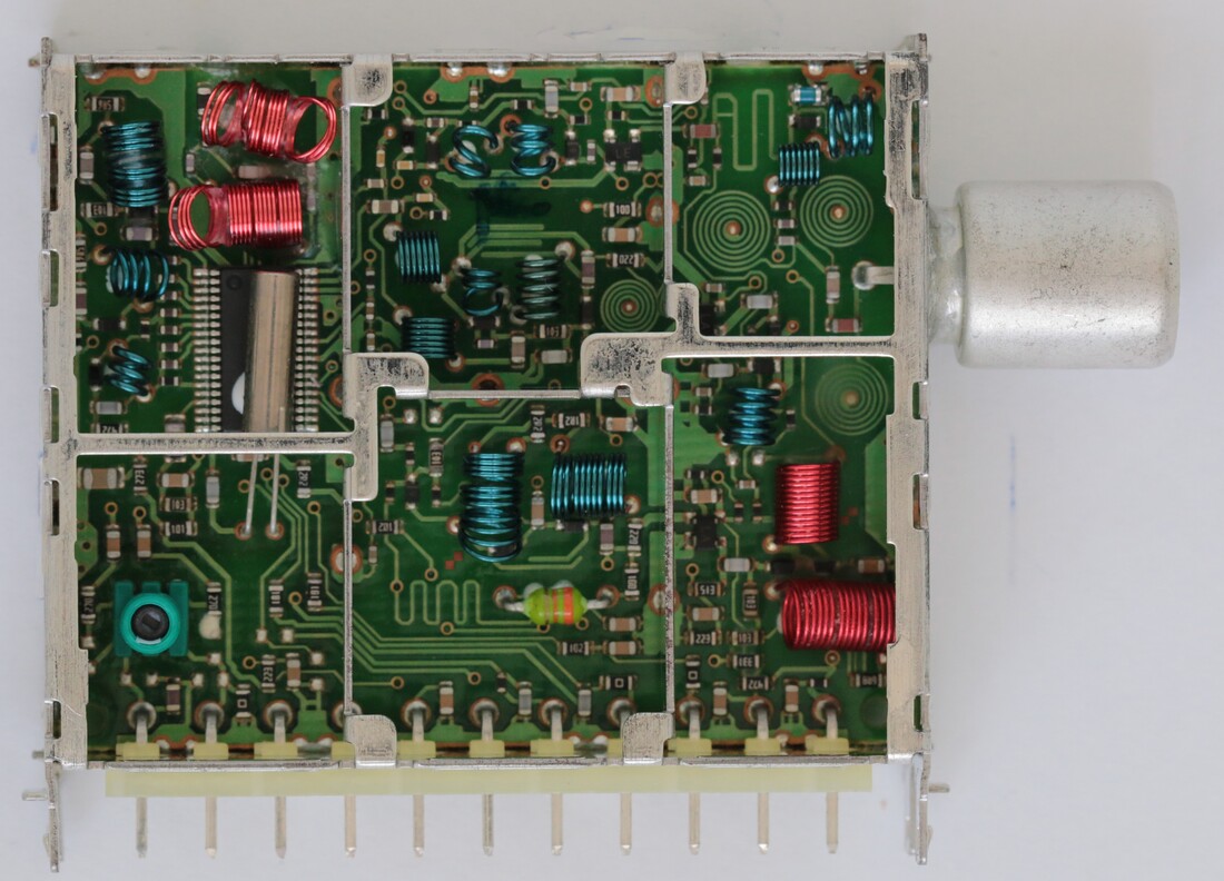
Top side interior view of the UV1318S/AI-Mk3 high performance tuner. Upper left the new multi-pole IF-filter, lower left the Sagami trafo to make the asymmetrical IF output. [Henk van der Wijst collection]
|
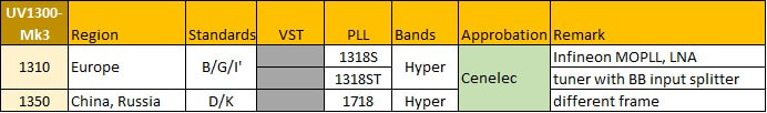
Overview of the main types with in the UV1318-Mk3 tuner family.
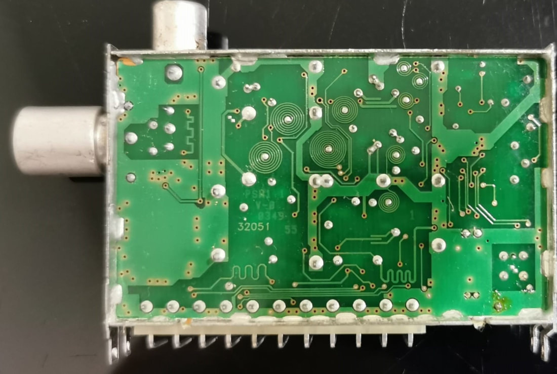
A-side view of the Philips UV1318ST/AICHN-3 splitter-tuner. The suffixes mean asymmetric IF out (A) IEC connector (I) China PAL-D/K IF of 38,0MHz (C) horizontal mounting (H) and no N-1 trap (N). [Kwong Kam Choon collection]
|
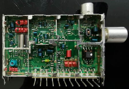
Top-side view of the same UV1318ST/AICHN-3. Note that the tuner section is, apart from the pin location, identical to the UV1318S. In the rightmost section the LNA with large Sagami feedback trafo below, above it the splitter trafo. [Kwong Kam Choon collection]
|
The UV1318 was introduced in the 2000 EM platform from Brugge, where it seems to have been used for the larger screen sizes. In the derivative FM and FLV/FLP chassis for LCD and plasma it was already the standard tuner, which remained so for the Jaguar platform. Also the LC4 mid end LCD chassis relied on the UV1318. In most of the Jaguar chassis two tuners were present, one UV1318ST as input splitter-tuner, of which the tuner section acted as the secundary tuner for PIP or dual window. The loop-through output went to the main tuner, which could be an UV1318S for analogue DW/PIP but increasingly a TD1316A-Mk2. For those sets that did not need a secondary tuner, for mechanical compatibility a dummy module was required which only acted as a loop-through. This was the UV1300T, which looked like a tuner but was empty apart from an RF track between input and output connector.
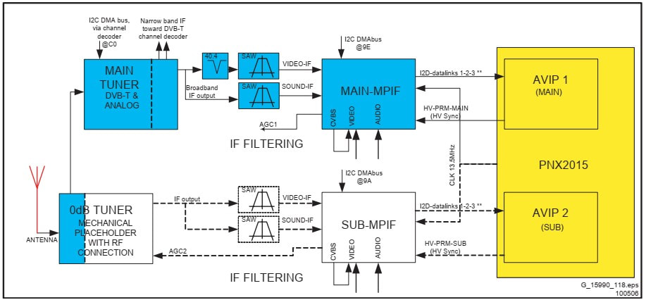
Front end block diagram of the Philips FJ3.0E Full Jaguar chassis in case of only the main tuner. A dummy tuner is used to provide the loop-through function, as far as known the only module ever produced by the Philips Tuners organisation that did not contain actual circuitry! [Philips FJ3.0E Service Manual, 2006]
|
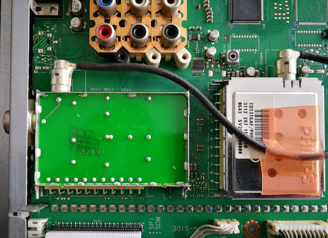
The front end section of the Small Signal Board of the Philips 32PF9731 LCD TV, with opened dummy UV1300T module, next to the TD1316AF/PHP-2 digital terrestrial tuner. [Pieter Hooijmans collection]
|
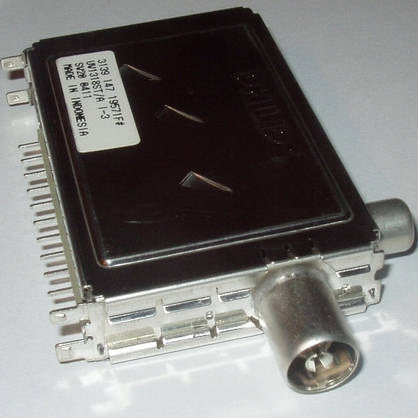
Nice frontal close-up of the standard UV1318ST/AI-Mk3
|
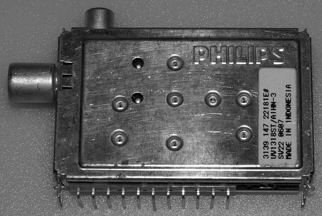
Same tuner as on the left, but now horizontal mounting (H) and N-1 trap (N).
|
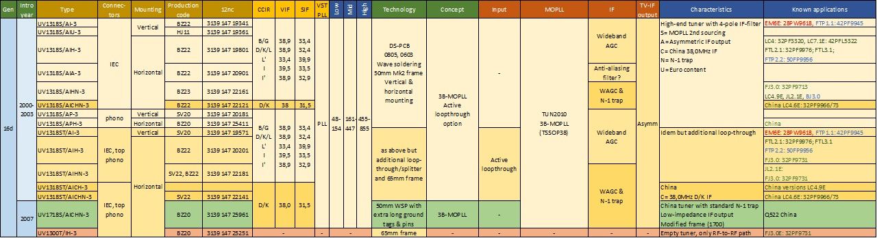
Overview of the Philips family of high-end UV1318S tuners and UV1318ST splitter-tuners. The UV1718S was designed much later, in 2007, for electrical compatibility with the UV1318 but in a different frame. Production codes refer to factories (SV=Singapore, BZ= Suzhou, HJ= Kwidzyn). In the known applications column red= CRT TV, blue= plasma TV, green= LCD TV.
Standard tuner cost reduction investigations
Almost from the start of the World Standard Pinning (WSP) it was clear that the price erosion of the tuners was not going to stop, on the contrary. So even while the UV1300-Mk2 and Mk3 were being developed, parallel projects were started to investigate fundamental cost reductions. Although we won't dive into the details, it is interesting to have a quick look at what type of joint design-technology options were considered for cost reduction, apart fromt he classical silicon integration and component size reduction.
|
One of the options discussed for quite a while within the BU Tuners was laser coil alignment. As we have seen in the CD1300 and UV1300-Mk2 and 3 families, it was possible to replace many of the classical wire-wound air coils by printed coils on the PCB. But the coils that needed alignment obviously could not be printed, unless they could be changed afterwards. This was possible by using a laser to cut the metal of a printed coil. To-be-aligned coils were designed with a large solid inner metal contact, the inductor wire spiraling out to its outer contact, see the lay-out picture. The laser track would essentially cut into the central disk, thus lengthening the spiral and increasing the inductance. Although this construction was necessary to allow inductance increase under trimming, it immediately resulted in one major drawback: the inner part of the inductor was blocked by the inner disk, blocking the free flow of the magnetic flux lines. In practice this lead to a lower Q-factor of the inductor.
Based on the UV1300-Mk2 in 1997-98 a pre-development project ran in Krefeld to investigate the feasibility of the laser alignment concept. Without going into the details, results were disappointing, mainly because it was very difficult to reach the same performance as a standard tuner. Main cause for this was the lower quality of the inductors, as well as parasitic and stray effects. The concept was consequently abandoned. |
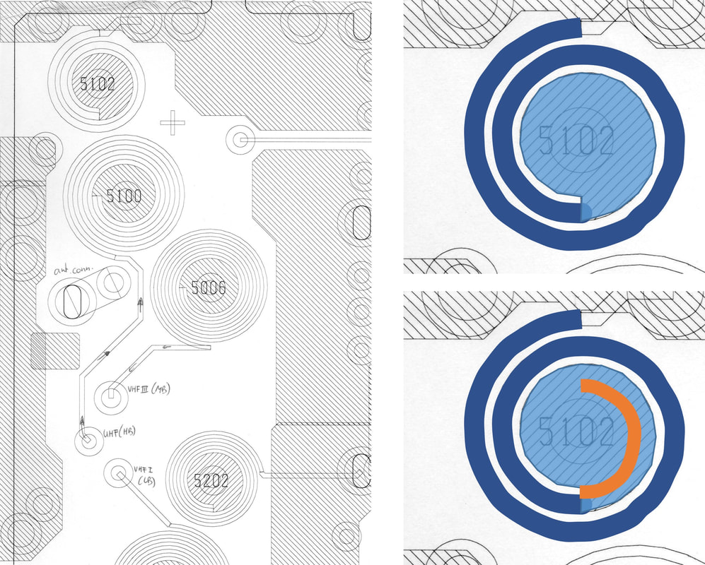
Principle of the laser alignment, with on the left a lay-out example with 4 coils. Upper right coil 5102 is enlarged to show the starting point, with light blue the central disk and dark blue the inductor spiral. At the bottom the typical track of the laser cut (orange) to increase the spiral inductor length.
|
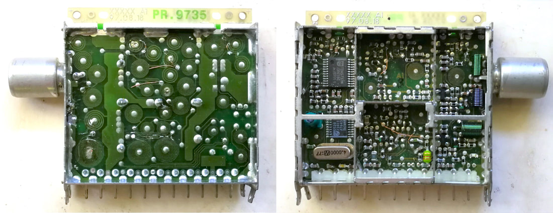
A-side (left) and B-side (right) of the UV1316L prototype with all but three inductors printed, and some laser cut for tuner alignment. [via Martin Barnasconi]
|
By 2001 the pressure was building up again, and a new effort was made to find possible cost reduction solutions. The main topic from this analysis was chip-on-board (COB), using an IC without package, directly wire-bonded onto the PCB. Theoretically this saved the packaging cost of the IC, and was a topic Tuner Engineering had been promoting for a long time. Again a pre-development project was done, using a slightly modified version of the TUN2000, the TUN2001. Like for the laser alignment the conclusions were not positive. The main reason was related to the IC manufacturing flow. In case of an unpackaged IC the final check of an IC can no longer be performed, that requires packaged ICs. The fall-off (faulty ICs) will now not be detected during IC final test, but at tuner final test, with much higher rejection cost. The conclusion was that the migration to smaller packages like the HVQFN would be more cost-effective once they became cheaper. This would indeed happen with the Mk5 generation.
|
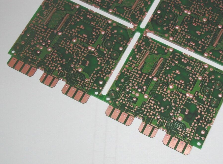
Another proposal that did not make it to production: replacing the pins by (extended) PCB contacts. [via Darko Jancin]
|
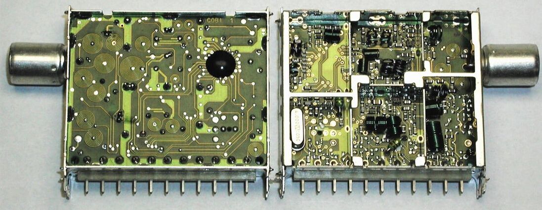
Prototype of a UV1316-Mk3 with Chip-on-Board (COB). The wire-bonded IC has been protected with a so-called epoxy glob top. [via Darko Jancin]
UV1300-Mk4, 2004
By the year 2003 the World Standard Pinning (WSP) had done its devastating effect: tuner prices had reduced almost 5-fold, from just below 10USD at the introduction in 1996 to 2USD by 2003. And it did not look as if this trend would end, requiring a next generation UV1300 with a further structural cost reduction. This became the UV1300-Mk4, with a target cost as close to 1USD as possbile. The main approaches to reduce the cost versus the Mk3 were still according the standard approach, since, as shown, neither laser alignment nor COB provided any cost reduction:
- Return to the single sided CEM3 PCB, as used in the original UV1300-Mk1.
- To avoid the problems of the Mk1 with frame soldering, a new PCB-to-frame atachment was introduced, requiring a frame modification. Holes on the periphery of the PCB fitted on nine pins on the frame, providing mechanical fixation and good RF grounding. With these changes the tuner still passed the critical environmental tests, especially Nb.
- Despite the use of 0603 and even occasional 0402 SMDs wave soldering was still possible, being cheaper than reflow.
- A massive switch to Chinese component suppliers, where the more expensive Japanese quality suppliers (TDK, Murata) were only used for critical components. This required approval of the very powerful Consumer Electronics Supplier Board Management Team (SBMT), but under pressure of the cost targets the new Chinese suppliers were approved.
- The key component was the Philips Semiconductors TDA6508 MOPLL (the mirrored version of the TDA6509 because it moved to the other side of the PCB).
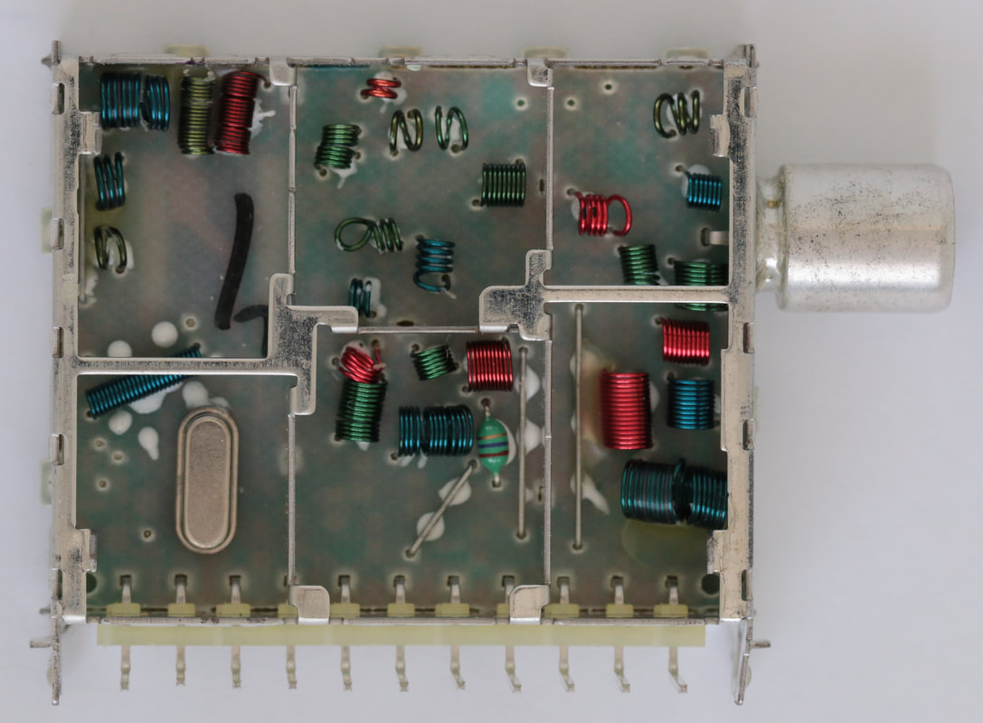
B-side top view of the Philips UV1316E/AIH-Mk4 PAL tuner, that returned to the use of CEM3 single-sided PCB. All inductors have become air coils again. Also note the four long bridging wires to compensate for the lack of tracks on both sides of the PCB. [Henk van der Wijst collection]
|
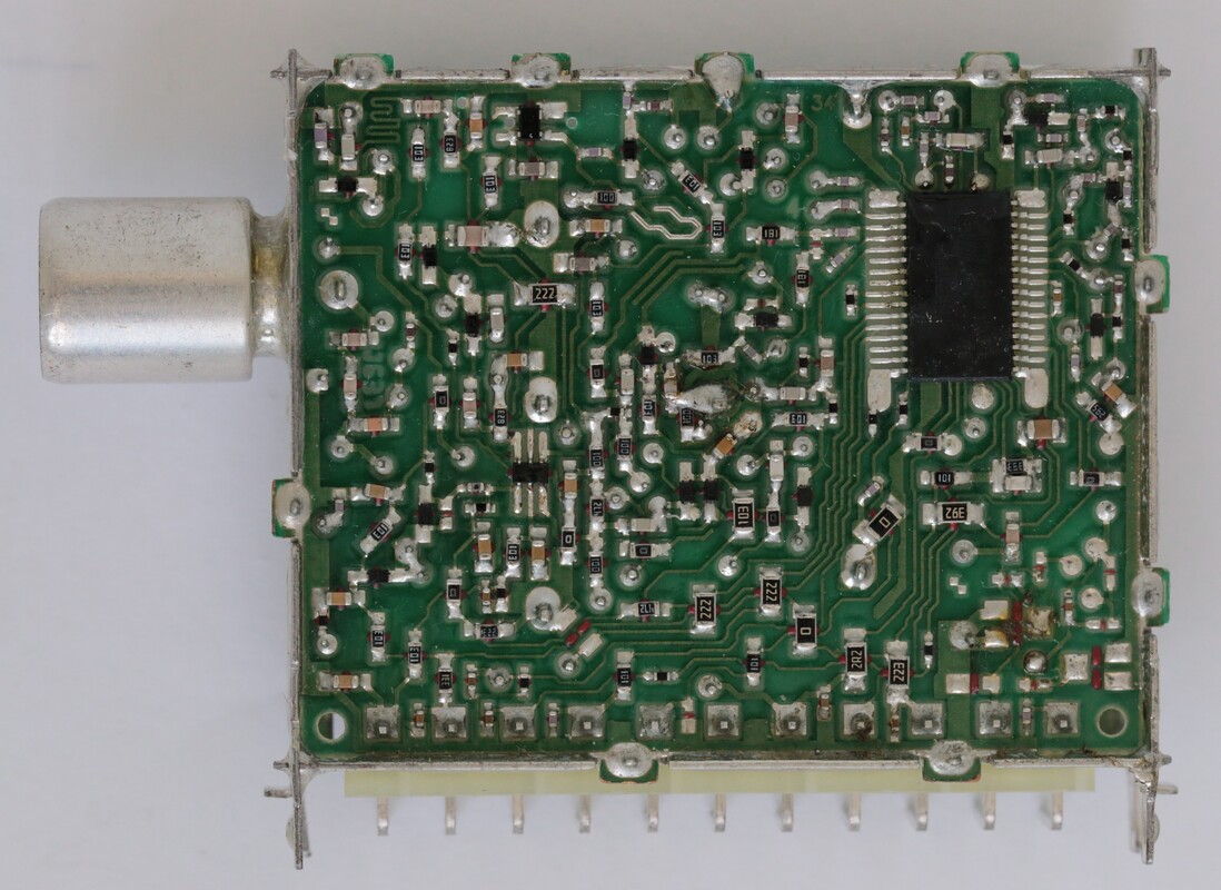
A-side bottom view of the same Philips UV1316E/AIH-Mk4. Noteworthy are the 6-pin dual MOSFET centre-left, the TDA6508 MOPLL and the nine newly designed PCB-to-frame attachments on the PCB periphery. [Henk van der Wijst collection]
|
A non-technical but equally important element of cost was diversity reduction. Where the Mk3 family still counted 40 (known) types, including splitter, loop-through, FM-radio and one VST model, the Mk4 would have none of this. The core model was the UV1316, with a very limited set of options: symmetrical or asymmetrical IF output, three lengths of IEC and one phono connector, and vertical or horizontal mounting. The NTSC tuner UV1336B was available in two versions, the B indicating that for NTSC tuners the Alps band limits still had to be followed. Especially the European 1316 was quite successful, being used by Toshiba/Beko, Daewoo and Vestel for their PAL sets.
However, also this family did not escape some diversification. When Philips BGTV threatened to increase the share of Alps tuners, supposedly because of lower prices, the BL Tuners - remember that until January 2004 the tuner activities were in the separate Singapore-based BL Tuners - defined the UV1316E-Mk4, the E referring to Excellence. This excellence was achieved through an improved 4-pole IF-filter, although this feature might also have been used for other customers too. In any case three Philips versions were produced: the UV1316E (Europe), 56E (China and Russia) and 36BE (US and Latam). These were mainly used in the last Philips CRT chassis L05, L06 and L07 as well as the first small screen LCD chassis LC4. During the life time of the Mk4 generation tuner prices, as expected, eroded further down to 1,65USD. Although the Mk4 allowed more aggressive pricing, it could not stop the structural decline of the analogue tuner market, with the switch-over to digital TV and hybrid tuners starting now. Where from 1995 to 2003 the annual analogue tuner volume produced hovered around 16,5-17Mio units, from 2004 a steady decline set in till only 5Mio analogue tuners were left in 2007. As such the UV1300-Mk4 was the last generation high volume analogue Philips TV-tuners.
However, also this family did not escape some diversification. When Philips BGTV threatened to increase the share of Alps tuners, supposedly because of lower prices, the BL Tuners - remember that until January 2004 the tuner activities were in the separate Singapore-based BL Tuners - defined the UV1316E-Mk4, the E referring to Excellence. This excellence was achieved through an improved 4-pole IF-filter, although this feature might also have been used for other customers too. In any case three Philips versions were produced: the UV1316E (Europe), 56E (China and Russia) and 36BE (US and Latam). These were mainly used in the last Philips CRT chassis L05, L06 and L07 as well as the first small screen LCD chassis LC4. During the life time of the Mk4 generation tuner prices, as expected, eroded further down to 1,65USD. Although the Mk4 allowed more aggressive pricing, it could not stop the structural decline of the analogue tuner market, with the switch-over to digital TV and hybrid tuners starting now. Where from 1995 to 2003 the annual analogue tuner volume produced hovered around 16,5-17Mio units, from 2004 a steady decline set in till only 5Mio analogue tuners were left in 2007. As such the UV1300-Mk4 was the last generation high volume analogue Philips TV-tuners.
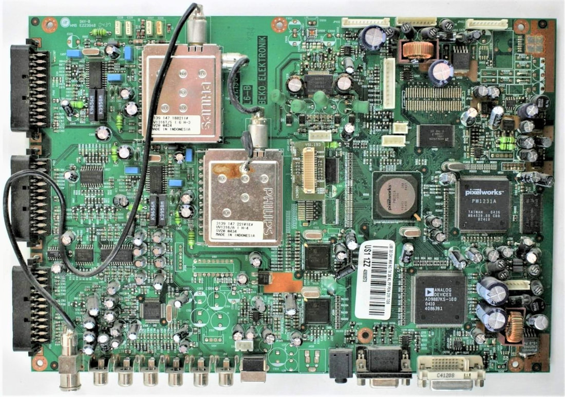
A dual tuner application on a Toshiba/Beko chassis. Since the Mk4 family did not contain splitter-tuners the upper input tuner is a UV1316T/SIGH-Mk3, while the lower tuner is the a UV1316/AIH-Mk4. [Spares2Repair.co.UK]
|
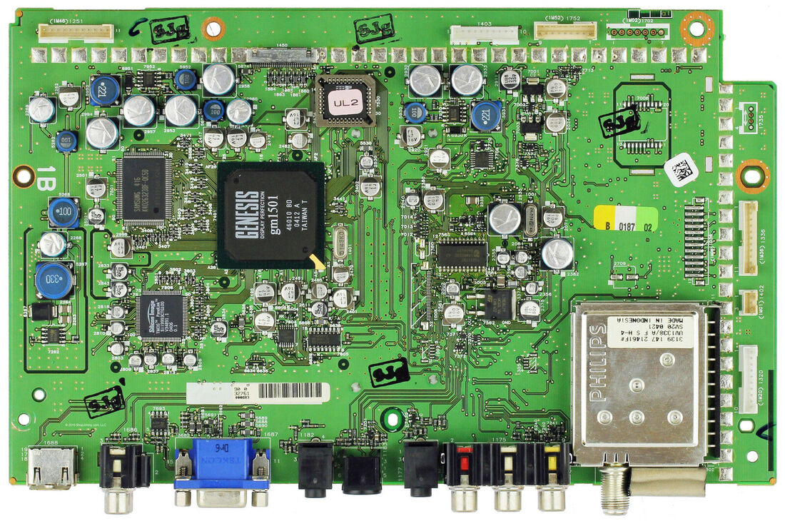
The small signal panel of a Magnavox 30MF200 LCD chassis. The tuner is a UV1338/AFSH-Mk4. The large ICs are a Genesis GM1501 LCD Scaler, a SiliconImage HDMI transceiver and a Samsung memory.
|
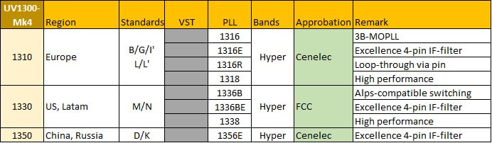
Overview of the main types of the Philips UV1300-Mk4 tuner family. This was the first generation that no longer included any VST types, all tuners using 3-band MOPLLs.
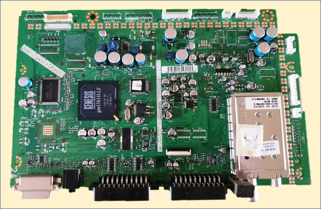
The Philips UV1318SD-ACPHN-Mk4 on the small signal panel of the 26PF5520. This was one of the first LCD chassis, LC4.3 from 2004. The product code says UV1318 high end tuner, with IFX MOPLL (S), dual input (D), Asymmetrical IF output (A), medium long IEC connector input (C), phono loop-through output connector (P), horizontal mounting (H) and N-1 trap (N). This was the only 1318 tuner within the Mk4 family.
|
A last Mk4 family extension were two high performance tuners, the UV1318-Mk4 and UV1338-Mk4 for PAL and NTSC. In both cases the high-performance probably referred to the use of a 4-pole IF filter. THe UV1338-Mk4 used the standard 50mm WSP frame like all other Mk4 tuners. The UV1318SD-Mk4 was the only exception, using the longer 65mm frame to accomodate a dual-input. It was the last high-performance (18 or 38) tuner by the BL.
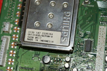
The UV1318DS/ACPHN-4 inside the 32PF5520D TV from the LC4.3 chassis.
|
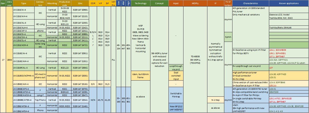
Overview of the Philips UV1300-Mk4 low-cost standard tuner family. After initial launch in Batam (SV20 production code) all tuners moved to Suzhou (BZ21 and 22) for volume production.
Philips Research Silicon Tuner project, 1999
By 1999 it was twenty years ago that the big Weinerth Integrated Micro-Tuner (IMT) project had been cancelled, and the topic of fully integrated tuner solutions was effectively burried for those twenty years. Never had so many engineers (around 70!) worked on a single tuner development and nevertheless it had failed. But in the subsequent twenty years silicon had gone through a tremendous number of improvement cycles, and now Qubic3 32GHz BiCMOS technology was available. End 1998, when I returned from two years Tuner Development in Singapore to become Department Head of the Philips Research group Integrated Transceivers in Eindhoven, there were no people left that had worked on the IMT project, and the taboo on integrated tuners had evaporated. On the contrary, especially Semiconductors Strategic Marketing Consumer was in a slight state of panic due to the emergence of Microtune, a Dallas (Texas) start-up launching US Cable dual-conversion integrated tuners. In that same year Microtune had started sampling an IC that was made using the IBM 0,8um BiCMOS technology, and consumed 4W of power and cost 19,5USD at low volume. Hardly numbers that should scare the Philips IC people, given the power and cost of a regular tuner and its IC. On top of that it showed all the classical drawbacks of the dual conversion concept, especially related to Noise Figure and input dynamic range. Despite all that the Semiconductors Consumer management was very alarmed.
|
The Research group therefore started a fresh study project into the feasibility of an integrated tuner, led by RF architect Jan van Sinderen and filter expert Eduard Stikvoort. In contrast to Microtune the objective was a full off-air tuner performance, and in the evaluation the dual-conversion concept obviously did not survive the selection process. Towards the end of 1999 a proposal had been worked out for an architecture that was on paper fully integratable and should be able to meet analogue terrestrial receiver specifications. But the Semiconductors Consumer management wanted bold steps, and acquisition discussions with Microtune had started! In November 1999 a small team including myself went to Plano, Texas, for a technical due dilligence, with as main question "will the Microtune concept potentially be able to meet terrestrial specs?". Obviously it did not, there were no performance surprises. And although it showed solid performance on many cable tuner parameters, dynamic range and IP2/IP3 were clearly a fundamental problem. Noise Figure was reasonable, but at the expense of very high power consumption. As had the Weinerth tuner! In contrast the MT2000, as it was called, featured some clever adaptive LO frequency management to avoid that any of the many beats between LO1 and LO2 ended up in the signal band. When this was reported back, the Consumer management grudgingly had to admit that an acquisition made no sense. As a result the attention was fully back on the Research Integrated Tuner project.
|
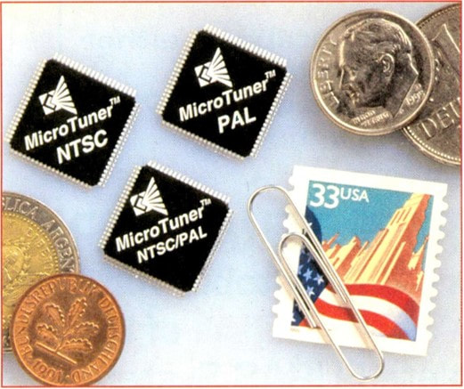
Publicity around the Microtune MT2000 cable Si-tuner, that upset the Philips Semiconductors management. [Television magazine, October 1999]
|
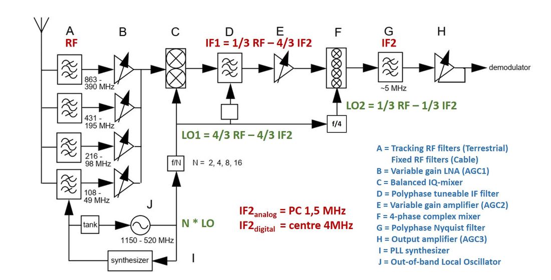
The starting point for the Research Silicon Tuner project, the 6-mixer architecture. Using a 2-step down-down conversion resulted in a very low IF of a few MHz. Polyphase filters were used in the IF (tunable) and 2nd IF (fixed). The latter filtered all negative frequencies including N-1. No SAW filter was therefore required. For good dynamic range and linearity tracking RF filters were still required. The LO was out of band and divided by 2, 4, 8 or 16 for each of the four input bands.
|
So, end 1999 the Integrated Tuner project started, with the same ambition but on a considerably smaller scale than 25 years earlier. The formal team was 6 people in the NatLab group Integrated Transcievers, with support allocated from System Labs Eindhoven (SLE) for RF measurements and Hamburg (SLH) for IF support. The BU Tuners in Krefeld formally sponsored the project and gave system defintion support. Of course the BL Tuners of Semiconductors in Caen was the intended receiving end of the project. Given the emerging Si-Tuner competition there was a lot of pressure from Semiconductors Strategic Marketing, and final prototypes were targeted for 2003.
|
|
The architecture that was selected, targeting off-air reception of analogue TV, was the 6-mixer concept, with first a down-conversion to roughly one third of the received frequency, followed by a fully balanced complex four-phase mixer step to a very low IF. To avoid problems with full zero-IF the picture carrier 2nd IF was at 1,5MHz, and the total low IF band thus from 0 to 7, 8 or 9MHz (for RF channel bandwidths of 6, 7 and 8MHz, respectively). For selectivity the Si-Tuner relied heavily on polyphase filters, which, given complex input signals, are able to have asymmetrical filtering characteristics. Another advantage is that polyphase filters can be made with RC elements, thus omitting the need for high-quality inductors that are difficult and costly to integrate. Some other characteristics and benefits of the architecture were:
|
Tuner Theory 18: RC-Polyphase filters
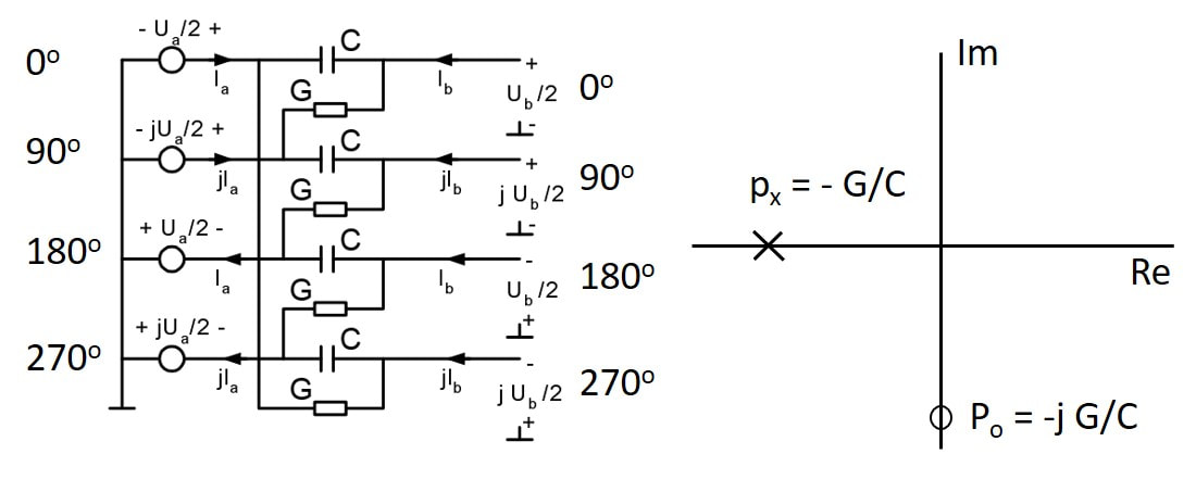
Concept of a single-section passive RC polyphase filter. As shown it requires four quadrature inputs and generates four quadrature outputs. On the right the complex pole-zero image.
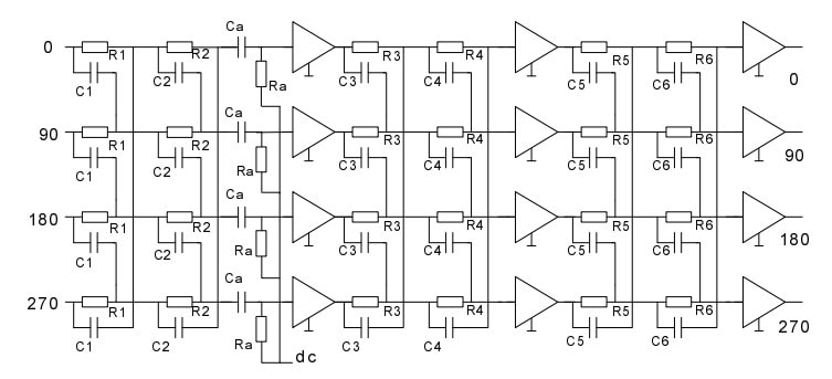
By cascading multiple unit sections as shown above, a "negative frequency reject"-filter can be made. Through successive placement of the poles a rejection band can be created. Because every section in principle has a higher impedance level for proper loading of the preceding section, after two filter sections a buffering impedance level shifter is inserted.
For the Silion Tuner six filter sections are used, that deliver poles at roughly -1, -1,5, -2,5, -4, -6 and -9MHz. Together they result in a rejection band from 0 to -9MHz which is effectively the N-1 channel of the wanted channel. The Ra-Ca combinations insert a hard zero at DC.
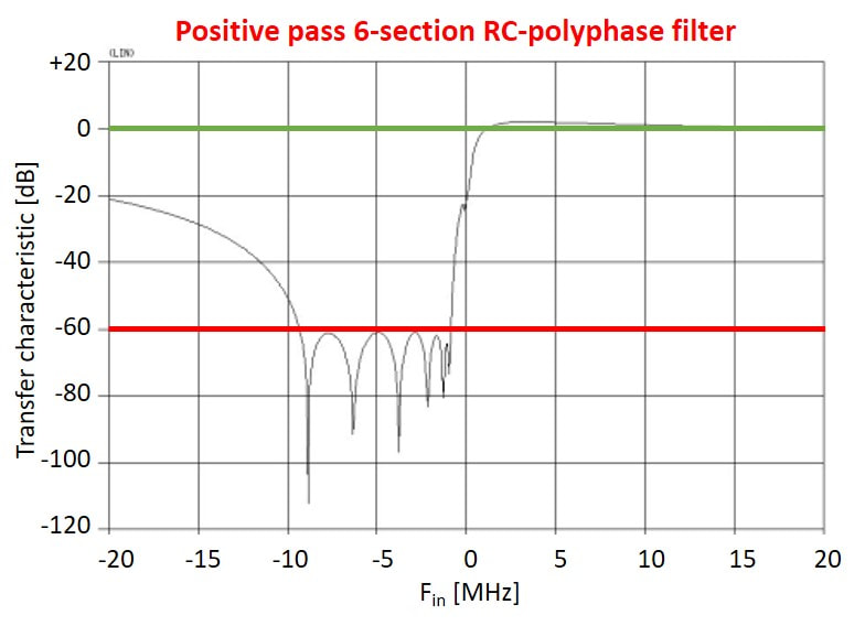
The resulting IF2 "positive pass" or "negative reject" asymmetrical frequency domain filter. The six poles are clearly visible. [All pictures from Eduard Stikvoort "Analog polyphase filters, NERG, 2003.]
|
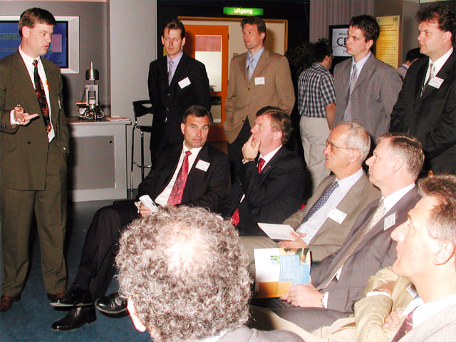
The Silicon Tuner project received a lot of attention from the Philips management. Here the author, left, is explaining the status to a delegation of the Philips Board during the 2001 Corporate Research Exhibition (CRE). Seated from left: Ad Huijser, then Head of Corporate Research, soon the Philips CTO; Hein van der Zeeuw, then head of Philips Optical Storage, later Philips Semiconductors; Marino Carasso, CTO of Philips Components; Gerard Kleisterlee, then Head of Philips Components, later that year the new President of Philips.
|
In 2002 Philips Semiconductors installed, based on a tradition from VLSI, the Design of the Year Award. The joint Research-BL team received the Silver Award, the highest price achievable because the Gold Award had to go, for obvious political reasons, to the TriMedia processor. Here the Research project team around their Department Head: from left Anton Tombeur, Eduard Stikvoort, Pieter Hooijmans, Marc Notten, Hans Brekelmans; front from left: Dennis Jeurissen, Jan van Sinderen (project leader).
|
TDA8270, the first silicon tuner family, 2003-2005
For product development of the first silicon tuner family the centre of gravity moved to Caen. The project was a major challenger, since it was not only an entirely new tuner concept, but also the first use - in parallel with the TDA6650 sigma-delta PLL - of QuBIC3. This was a big step compared to the previous bipolar-only HS5 technology, both in terms of RF performance (a doubling of the ft!) but also the availability of a 50um CMOS, allowing - for RF products - an unprecedented level of digital control on an RF IC.
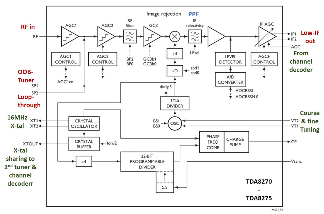
Block diagram of the Philips Semiconductors TDA8270 first generation cable silicon tuners. [TDA8275A - Siliocn Tuner for PC Applications, 2004]
|
The concept went through a number of changes, but in the nd settled on an architecture along the main lines as described in the previous section, and as features:
|
|
To support the higher LO frequency range of 843-1760MHz and to improve phase noise, the TDA8270 introduced a four times higher crystal reference frequency of 16MHz, as compared to the traditional tuner (MO)PLL 4MHz. In the same way that the tuners had been doing for a while already, the IC also provided a buffered crystal sharing output, to be used by the demodulator or channel decoder.
With respect to the application four different sub-versions were introduced by end 2003, all based on the same die:
The initial target of the TDA8270 was to achieve at all cost a (much) lower power consumption than the MicroTune IC's. Although these had started at a whopping 3,5W, the second generation had brought this down to 1,5W. The power consumption of the first generation TDA8270 at 1,3W was indeed lower, but not with a spectacular margin. Almost immediately after release of the first generation a re-design for power optimization was started, based on the same architecture but tuning most of the circuits. One major adaptation was that the original single oscillator with programmable divide-by-2/4/8/16 to create the band-specific LO signals was replaced by four separate VCO's, one per band. This became the TDA8270A family, launched in 2005, with a power consumption of 1,15W. |
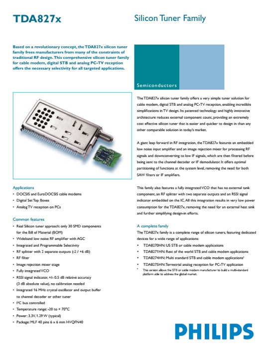
The first announcement of the TDA8270 family. An Alps frontend was used as negative size reference. [2003]
|
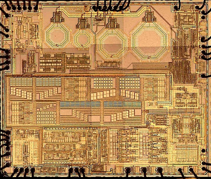
Picture of the TDA8270A die with bond wires attached. At the top the now four separate LO VCO coils. Centrally the very regular structures of the 6-segment IF polyphase filter. The die size is 3,7 by 3mm in QuBIC3.
|
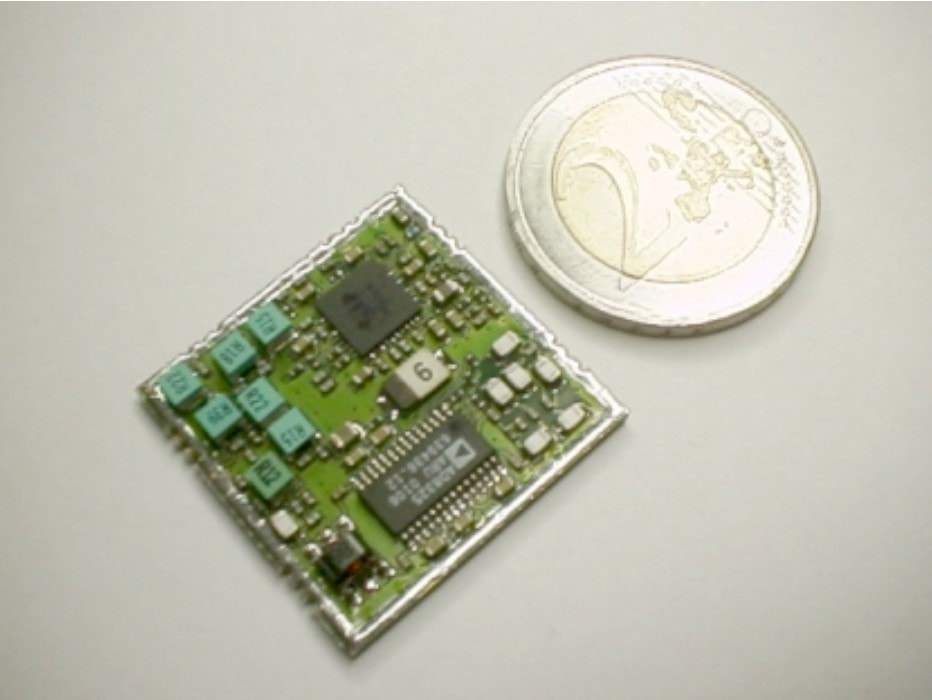
As part of the joint analysis the BL Tuners in Krefeld built a prototype Ball Grid Array (BGA) module based on the TDA8270A, with the same functionality as the CDX1236. At the time they concluded the IC was not yet good enough for analogue reception. [Frank Langenberg, Status Report CDX with TDA8270, April 2002]
|
As soon as the ICs were available, Semiconductors started a major activity to make reference designs around the TDA8270(A) with the clear ambition to sell the ICs directly to set makers (of cable modems, STB or PC PCI card), by-passing the Tuner module makers. "Tuner-on-the-Board" became the Caen strategy. For the digital cable applications the TDA10021 and from 2003 the TDA10023 QAM64/256 channel decoders were used. The TDA10023 contained additional filtering for optimal use in combination with the TDA8270. For applications that also required analogue reception, in practice only the PC off-air, the TDA8290 digital IF IC was developed by the Hamburg IF group. Like the TDA10021/23 it used a 54MHz 10-bit ADC to digitize the low-IF singal for digital demodulation.
One important design win of the TDA8274A was Broadcom, at the time a rapdily growing start-up in the digital SoC domain that was growing to the leading player in the US cable channel decoder and system controller market. Broadcom needed a compact low power tuner for its cable modems and turned to Philips, but insisted on Broadcom-style coding of the tuners, to hide the fact they were not designed by themselves. This became the BCM3420, which ramped immediately to very high numbers and some 25Mio$ turnover per year.
One important design win of the TDA8274A was Broadcom, at the time a rapdily growing start-up in the digital SoC domain that was growing to the leading player in the US cable channel decoder and system controller market. Broadcom needed a compact low power tuner for its cable modems and turned to Philips, but insisted on Broadcom-style coding of the tuners, to hide the fact they were not designed by themselves. This became the BCM3420, which ramped immediately to very high numbers and some 25Mio$ turnover per year.
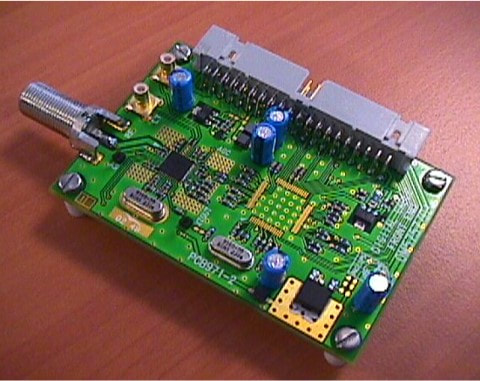
Reference design OM5757 of the TDA8270 tuner and TDA10021 QAM channel decoder.
|
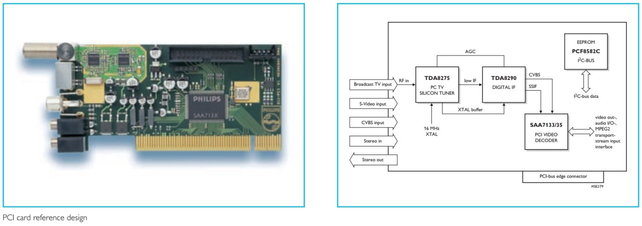
Philips Semiconductors Hamburg System Labs (SLH) reference design of the TDA8275 tuner, TDA8290 digital IF and SAA7131 PCI controller. Although all pictures show the tuner visible, in practice all these designs still required metal caps around the tuner section.
|
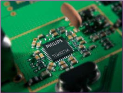
The second generation Philips Si Tuner, the TDA8275A in a tuner reference design. [Si Tuner for PC TV Applications, 2004]
|
And so, 25 years after the Weinerth tuner project, Philips finally had its integrated tuner. Although, obviously, still with its limitations: only for cable applications (and, despite the Semiconductor claims, marginally for PC TV), most suited for digital transmission and, although lower than competition, still with a high 1,15W power consumption. The TDA8270A family clearly needed further improvements. But at the same time it was a major step on the continuing road to higher integration.
|
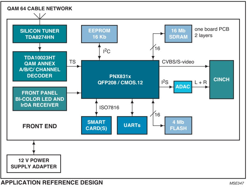
The Philips TDA8274 Si Tuner as part of the PNX8310-based Cable STB Reference Design, together with the TDA10023 QAM channel decoder. [Philips Semiconductors Nexperia Cable STB system solution, 2004]
|
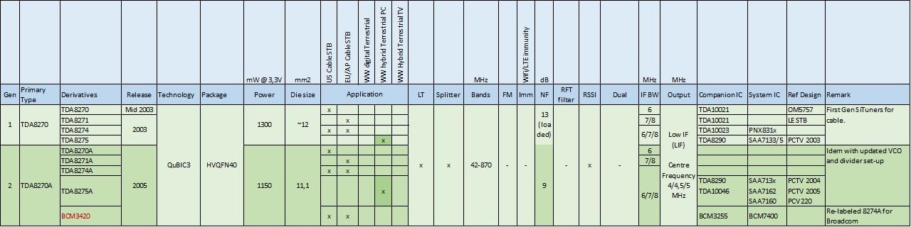
Overview of the first two generations of Philips Semiconductors Silicon Tuners, the TDA8270 and TDA8270A.
Philips Semiconductors Tuner business, 1998-2008
The tuner IC business of Philips Semiconductors originally started as a broader RF-IC business entity in Caen, France, but once the Mixer-Oscillator ICs took off in earnest, a dedicated Business Line Tuners emerged during the 1990's. By 1998 it had reached a healthy sales level of 100Mio$ (around 200MioHfl), roughly one third based on satellite RF ICs and the other 2/3rd on tuner MO and PLL. In that same year the first 3Mio$ sales of MOPLL ICs was made, based mainly on the TDA6400 family of switched 2-band MOPLLs for the UV1336. Like all businesses the BL had a fantastic year in 2000, with 25% growth, but then in 2001 the internet bubble burst. Fortunately the RF consumer business, mainly TV still, was not hit as dramatically as the STB and PC, the BL Tuners survived with a minor decline. Furthermore, in the clean-up of the Semiconductors organization after the closing down of the San Jose Silicon Valley activities, it received the Hamburg IF and Rennes channel decoder activities. Hilde Overath became the new BL manager, who "opened the windows" of the rather inward focussed French organization and intensified the co-operation with the BU Tuners (Krefeld and Singapore) and Research (Eindhoven). Which was urgently needed, because some big changes lay ahead.
|
If we compare the competition overview and leading tuner manufacturers in 2001 with the list of 1994, when the WSP standard was announced, some dramatic changes have taken place in those seven years.
|
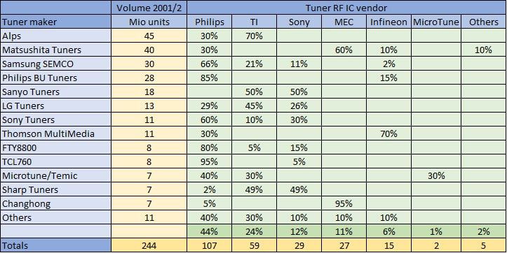
Overview made by the Philips Semiconductors BL Tuners of the leading customers and competitors in 2001-2002. Most numbers are probably accurate to within 5%, but the overall picture is fairly representative of the actual competitive situation.
|
Philips Semiconductor Tuners still held a respectable market leader position with around 44% share, but compared to ten years earlier especially Texas Instruments (TI) had emerged as a serious competitor. TI, a leading analog IC player, had opened or acquired an RF design centre in Japan, close to Alps, obtaining them as their biggest customer. Because TI had a similar or even larger internal industrial manufactuirng base than Philips, they could offer their ICs for very competitive prices and especially with the introduction of the MOPLL TI had taken market share. Despite the strong price erosion, similar to the one experienced by the BU Tuners at module level, the 2nd tier suppliers Matsushita, Sony and Infineon stayed active in the tuner RF-IC segment, although their limited volumes in combination with the low market prices (for most ICs now well below 1USD) must have made it hard to be profitable business. On the other end of the scale MicroTune, which had in the meantime acquired the Temic tuner module business, had established itself as the first silicon-tuner player, albeit with still very modest volumes.
|
There were a number of specific threats to the RF-IC business:
|
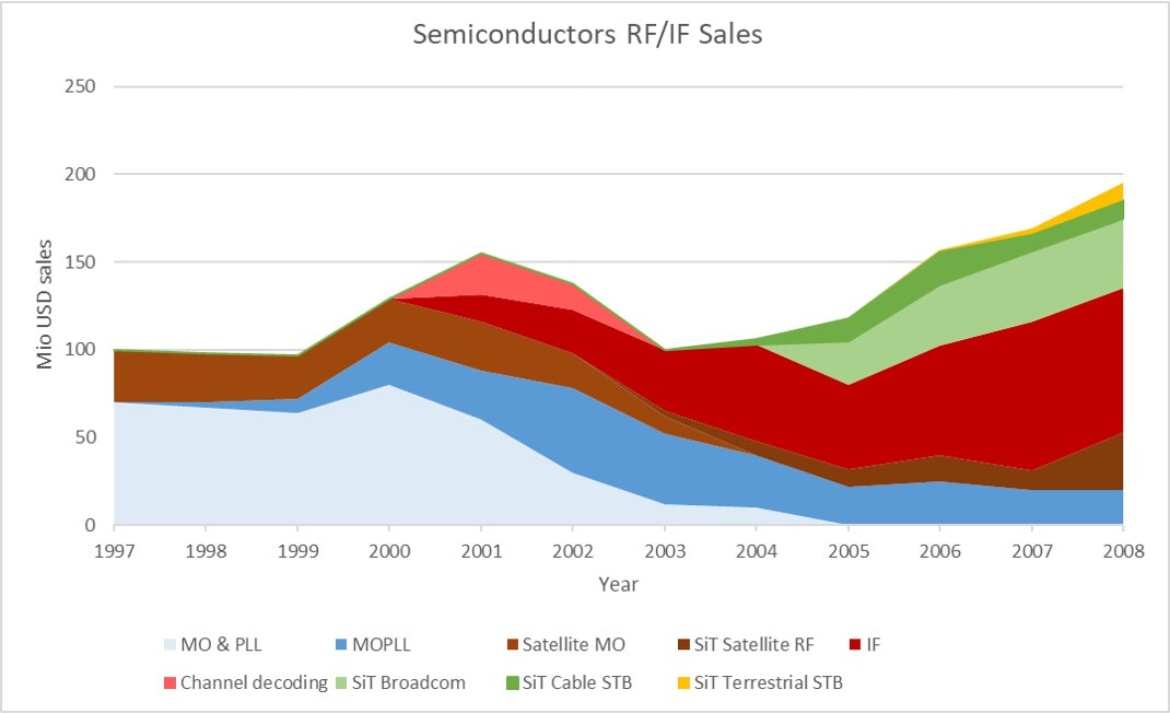
Overview of the Philips Semiconductors Tuner RF-IC business from 1997 to 2008.
|
- under the pressure of the World Standard Pinning, the emergence of TI as competitor, and the fundamental rule that integration should lead to cost reduction, the value of the new MOPLL business was lower than the combined MO and PLL business it replaced. The "classical" business of tuner MO/PLL/MOPLL and satellite RF-ICs thus steadily declined from 130Mio$ in the year 2000 to just 48Mio$ in 2004.
- the Si-tuner developments, however promising they were, took their time to come to finally well-engineered ICs, which was the 2nd generation TDA8270A that ramped in 2005. Only then the business showed a reversal back to growth. In the meantime the TDA6651 fractional-N PLL was volume-wise the main runner of the BL.
Just when the BL was recovering and releasing the TDA8270A Si-tuner, disaster struck: on December 12, 2003 a fire broke out in the main clean room of the Caen fab, destroying the entire production facility. Although a remarkably fast recovery and production catch-up was organized in other Philips Semiconductors fabs, it did have a major impact on the business, reducing the targeted sales in 2004 by almost half. It forced the BL to pronounce end-of-life of almost all its older products, especially those still based on the old Subilo technology from 1980. But everything has a good side, even a devastating fire, since it forced the BL to stop developing local technologies like HS5, and instead use the standard QuBIC4 technology from the East Fishkill (NY, USA) fab. Although the Caen fab was reconstructed, it would never see IC production again, limiting instead to passive integration technology (PICS). In 2007, Philips Semiconductors had become NXP by then, all development activities left the Caen industrial site and moved to a new R&D campus EffiScience at Colombelles, just North of Caen, on the re-developed terrain of a former iron works. The Caen fab was spun-out to the new company IPDia, focussing on the passive integration technology in 2009, which was acquired by Murata in 2016.

The Caen fire brigade trying to extinguish the massive fire in the Caen Semiconductor fab, December 12, 2003.
|
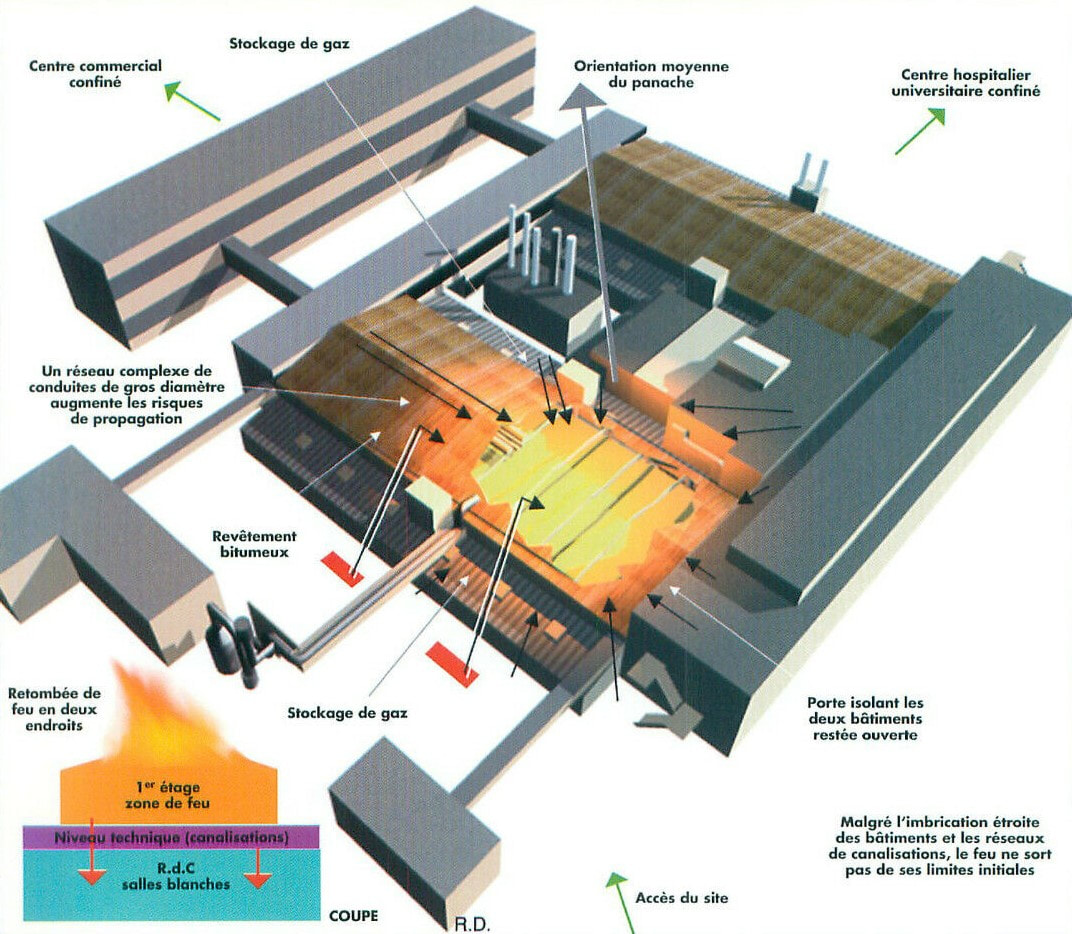
Schematic drawing indicating where the fire occurred. The building upper left is for Development.
|
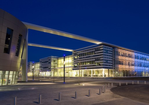
The new R&D Campus at Colombelle, where all Caen development and management moved in 2007.
|
|
In 2005 another round of strategic re-focus took place. After a sales peak in 2003, the MOPLL sales - mainly the very successful TDA6650, saw a dramatic price erosion. Although volumes were still very good (around 100Mio ICs per year, so around 50% market share) sales reduced from 48Mio$ to 22Mio$. Satellite sales, where despite the TDA8260 family of ZIF MOPLLs the market share had become much lower, suffered a similar fate. Both segments were thus declared as legacy, which meant from then on no further development of new products. The same was decided for the IF ICs, although on different ground, because the business was still growing. Here the reason was that TV SoCs were rapidly integrating the IF function, which had started with the One-Chip TV ICs but continued with more digitized ICs like the HIP, BOCMA and MPIF. It was expected that the same would happen in the PC world, the main application of the IF ICs through the FI/FM/FQ1200 Multi-Media frontends of Philips Tuners and its copiers. With the TDA9880 AFRIC family the maximum level of integration had been reached for standalone IF, and no major next steps were foreseen. At the same time the AFRIC family was very successful, also being used in the Philips L06 last high-end CRT and the LC7 LCD chassis. Nevertheless IF ICs were also declared legacy products, and the Hamburg team dissolved and transferred to the BU Automotive.
|

These boys and girl are playing around with a mask layer printed on their flag, but other than that it is difficult to see the link between this picture and advertising high-tech RF ICs. Life was getting tougher and tougher for engineers that thought they were in a technology company. Obviously, they were not, it was about feeling good! [BL TV Frontends presentation, 2002]
|
These decisions did not mean that sales went down quickly, on the contrary. MOPLL business continued till 2010, while IF sales only ended in 2013. In the meantime these segments were real cash generators, with no R&D and sales cost. The cash freed up this way was needed for the Si-Tuner developments, which were finally picking up that same year. From here on the BL TV Frontends, as it was called now, was entirely on Silicon Tuners for Cable and, the strategic target, off-air TV reception.
FQ1200-Mk5, the last analogue frontend family, 2004
Although the FQ/FM1200-Mk3 family had only just been released, in 2003, the Mk4 development was started almost immediately afterwards. The formal trigger of this was the new European Union Directive 2202/95/EC on the Restriction of Hazardous Substances (ROHS), banning such materials as Cadmium, Lead, Mercury, Chromium and a number of compound material like phenyls and phtalates. For RF Solutions this meant lead-free soldering, which became the main element of the new Mk5 family. It was a major project, especially with respect to purchasing and engineering/production, since lead-free soldering really requires different process optimization compared to classical soldering. There was quite some pressure from the market, because customers didn't want trouble and required ROHS-compliance as soon as possible. In the meantime competition on cost was intense, with Microtune/Temic, Samsung and LG continuing to sell almost 1:1 copies of the FM/FQ1200, of course at lower prices in an effort to grab some market share. So, to stay ahead of competition, a step was set by reducing the product thickness from 13 to 12mm, which was promoted as a 10% volume reduction.
|
From the electrical side the changes were minimal, the functionality remained first order identical to the FQ1200-Mk3:
|
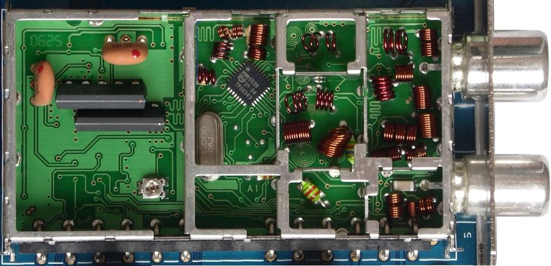
Top-side interior view of the Philips FM1216ME/IH-Mk5. The lower connector is the FM radio input, the two orange 10,7MHz ceramic filters take care of the IF filtering. The two SAW filters are required to cover all PAL standards.
|
- The Mk5 offered the very last FM-radio models, the FM1216ME and FM1236. Since its introduction in 1998 the FM-radio option had been extremely successful feature, and a main differentiator of Philips MultiMedia frontends (and later, as derivative, in the UR1300 tuners).
- To reduce diversity the main products were the FQ1216ME (Multi Europe), covering all PAL standards, and the NTSC FQ1236. Nevertheless, two region-specific versions were created: the FQ1256 for PAL-D/K in China (and Russia) and the FQ1286 for Japan.
- Fom the Mk3 the FQ1216PN (PAL-NTSC) concept was copied, where the TDA9886 for negative (PAL) and positive (SECAM) modulation as used in the FQ1216ME, was replaced by the TDA9885 for negative modulation only. With a different SAW filter the PN could receive all PAL (B/G/I/D/K) and NTSC (M/N), making it a global model except for SECAM. Especially AverMedia used it to substantially streamline their logistics.
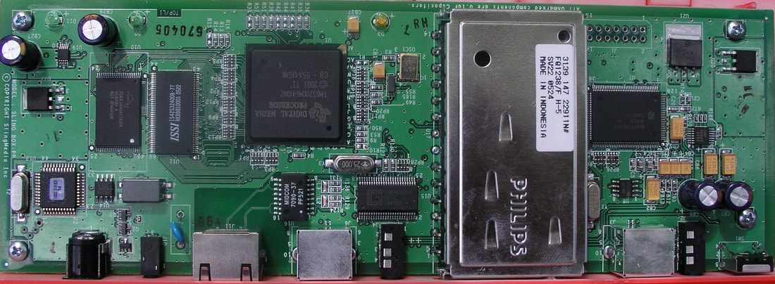
The Philips FQ1238/FH-5 NTSC frontend on a Sling Media Slingbox in-home TV distribution box.
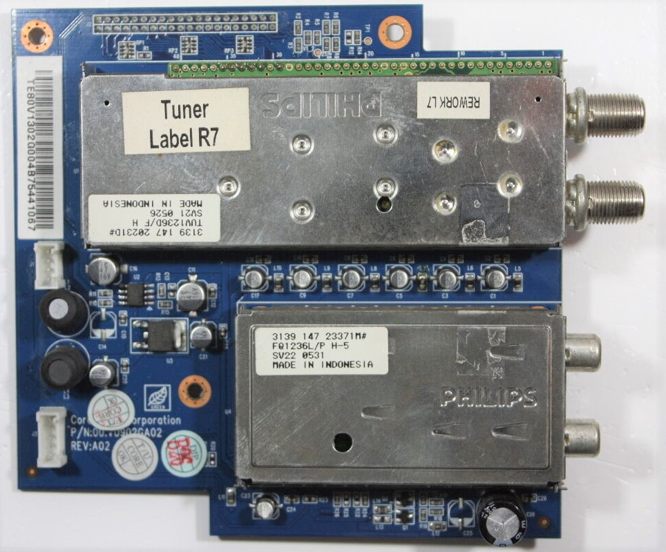
In the 2003-2007 years Personal Computer supplier Dell went into selling LCD TVs, mostly based on Philips frontends. This tuner board from the Dell W4201 contains two frontends: the FQ1236L/PH5 for the analog reception, and a TUV1236D/FH for the ATSC digital standard.
|
Competition in frontends was mainly coming from cheap and lower performance modules. At the same time the internal RF Solutions cost were increasingly determined - and limited - by the key components, especially the MOPLL and AFRIC. To create more differentiation against competition only one option remained: performance improvement, preferably in a not too expensive way. Three different and region-specific improvements were thus introduced, indicated by the high-performance last type number digit 8.
|
|
The FQ1200-Mk5 family continued the solid business of the predecessor Mk3 (and Mk4) generation, where the starting decline in the PC-card business was compensated by the increased use in the first generations LCD flat TVs. However, there were a few trends that worked against analogue (PC) Multimedia Frontends: the migration to digital TV standards; the move to laptops and tablets, that did not use plug-in cards; but more importantly the trend to streaming video IP, making the concept of watching TV reception on a PC obsolete. So, since the first sales in 1991, six generations of FI/FM and FQ frontends, some 35Mio high-valued and good margin products analogue TV/FM frontends had come at the end of their life cycle. The Multimedia frontends, despite regular neglect by BU management that had its fate linked to TV only, had been one of the main external flagship products of the BU/BL. Only two more hybrid generations of frontends were to continue the line of products in the coming few years.
|
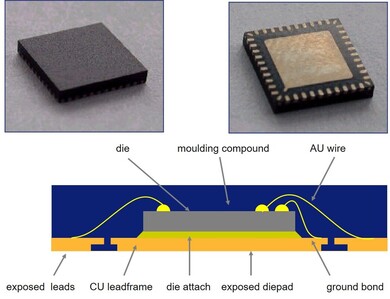
Around 2004 Philips Semiconductors introduced the HVQFN leadless over-moulded package. For good grounding it had an exposed die pad. It was developed for the mobile phone business, but then also quickly adapted by the consumer segments. For Tuners the IF ICs were the first, followed by the MOPLL and channel decoders.
|
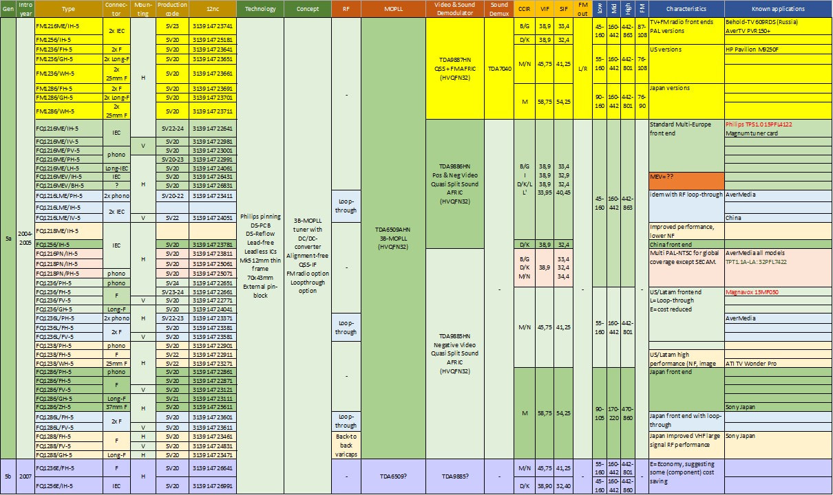
Overview of the Philips FM and FQ1200-Mk5 family of analogue multimedia frontends, the last generation for analogue TV only. Under applications red denotes Philips CRT chassis, green Philips LCD chassis.
FQD1200-Mk5 hybrid frontends, 2004
Where the FQ1200-Mk5 essentially was the FQ1200-MK3 with ROHS-compliance and a thinner frame, so was the FQD1200-Mk5 the successor of the FMD1200-Mk3. Main difference with the latter was that the FM-radio function was dropped, covering just analogue TV (full demodulation) and digital off-air (1st IF after SAW-filtering and AGC). The frontend was also fit for cable reception, for which a wideband input buffer amplifier was added. This guaranteed the required Open Cable CSO/CTB linearity requirements. Like in the FQ1200-Mk5 the basic models were the FQD1216ME multi-PAL and FQD1236 NTSC. In contrast, there was no China version, only a Japanese FQD1286.
|
Interestingly, in the FQD1200-Mk5 family only the PAL FQD1216ME type also had an RF loop-through version, the FQD1216LME. Why the NTSC no longer had a loop-through is not clear. The same Multi-Europe model also appeared with an additional LNA, the FQD1216AME. Although not 100% confirmed, this might well have been based on the NEC NEC2101 transistor, which provided a better Noise Figure than the standard BFG540. This version was only possible after the BL RF Solutions had moved to NXP, because within Consumer Electronics NEC was on the non-preferred supplier list and thus not allowed to be used. Possibly for the same reason a higher performance version FQD1218ME was released in the same period.
|
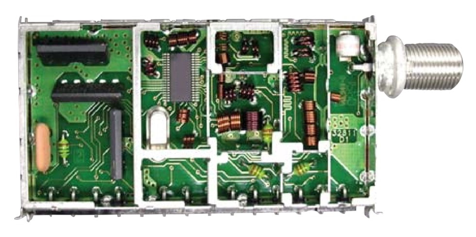
Top-side interior view of the Philips FQD1236/FH-Mk5. From the RF input a the right noticeable elements are: upper right the large ESD surge diode, the TUA6034 MOPLL, in the leftmost compartment the three SAW filters for (from the bottom) sound, analogue video and digital TV. The orange filter is a sound trap. [Philips RF Solutions, "FQD1200 hybrid analogue/digital video module", product leaflet, 2005]
|
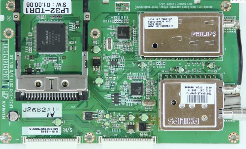
The period between 2005 and roughly 2010 saw the switch-over point of analogue and digital TV. In the meantime many systems contained complete signal chains for both. Here a Humax LT40 terrestrial STB for DVB-T. It contains a TD1316ALF DVB-T tuner with loop-through and an FQD1216ME/IH-Mk5 for analogue reception or a second "play-while-record" DVB-T channel. Each tuner is followed by a Philips TDA10046 DVB-T channel decoder.
|
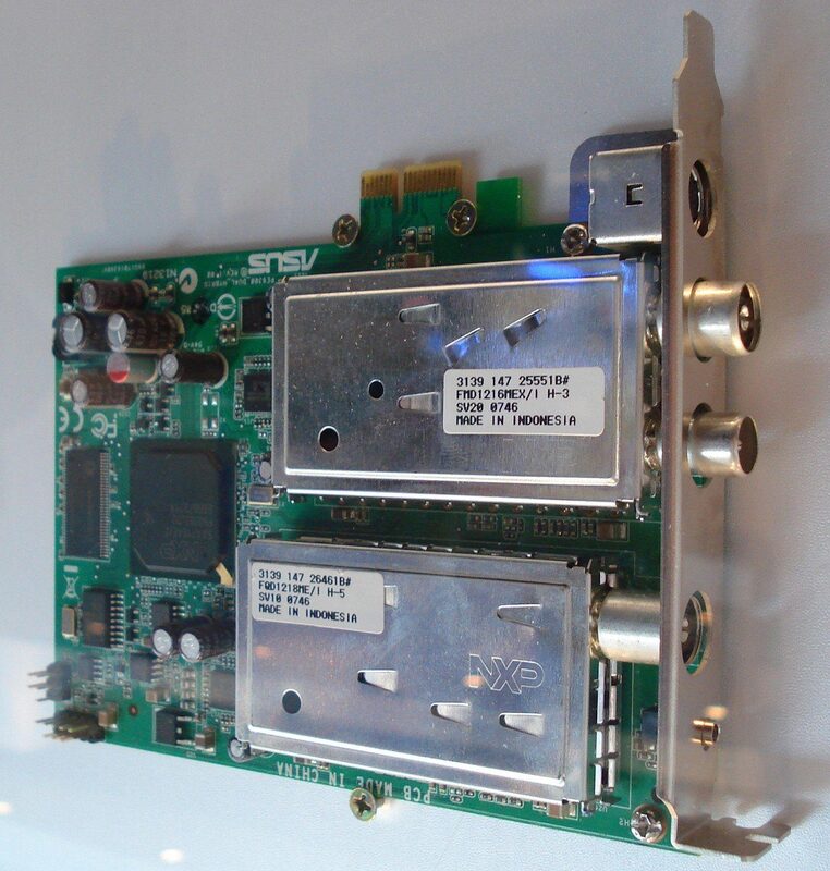
An ASUS PCI-Express card with on top an FM1216MEX/IH-Mk3 (for FM, TV and digital TV) and below the FQD1218ME/IH-5 (for analogue and digital TV). It is not entirely clear why two full hybrid frontends were used in parallel.
|
Like all products in this period, also the FQD1200 performance and functionality was largely determined by its two key components. For the OFDM digital reception the FQD1216ME switched, compared to the FQ1216ME, to the Infineon TUA6034. The FQD1236 for ATSC could stay with the cheaper TDA6509. Since the digital TV 1st IF path did not use the IF demodulator the TDA9886 (ME) and TDA9885 (NTSC) remained unchanged compared to the FQ1200. However, in 2005 a project started with Philips Consumer Electronics for a frontend based on the new MasterIF IC, the TDA9899. This was a "monster" IC, the ultimate in stand-alone TV IF demodulation that covered all analogue video standards and their sound, FM radio including car radio plus digital TV 2nd IF down-conversion. Philips CE apparently had high expectations of the MasterIF, since it was planned for the flagship Brugge chassis Q522 as well as targeted by the DVD business.
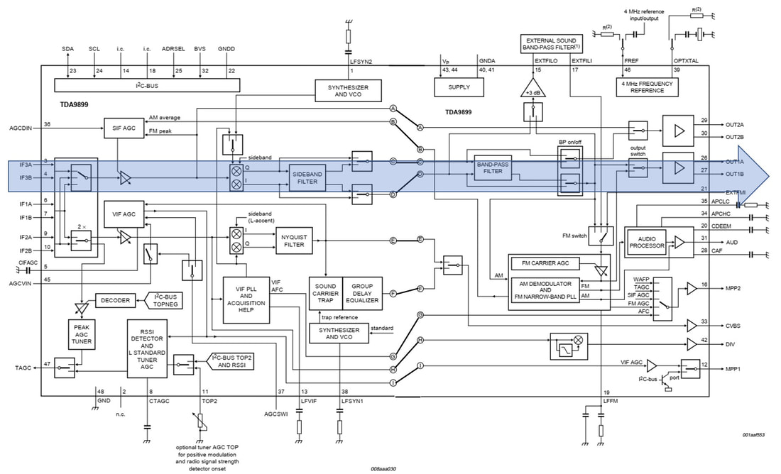
Block diagram of the Philips Semiconductors/NXP TDA9899 MasterIF IC for hybrid analogue/digital IF demodulation or second down-conversion. The IC is very complex, with many switches and configuration control to manage the enormous diversity in standards that was covered. Compared to the previous AFRIC analogue-only demodulator the main addition is digital-TV 2nd IF. The blue arrow indicates the main signal path for this function: IQ down-conversion to either ZIF or LIF, followed by selectable levels of bandpass filtering. [NXP Semiconductors TDA9899 Data Sheet, Rev.3.0 January 2008]
|
The FQD1200C-Mk5 with the MasterIF led to the following changes:
Prototypes of the FQD1200C were ready when, surprise, Philips Consumer Electronics decided they would put the MasterIF IC on the main board, not requiring a frontend. This killed the business case of the module, but being almost ready it was kept alive and other customers were sought, with limited success. |
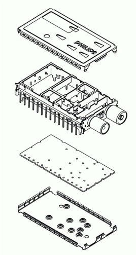
Exploded view of the FQD1200C-Mk5 mechanics. Note the M3 receptacle between the RF connectors. [RFS FQC1216CME PRS Evaluation Report, 2006]
|
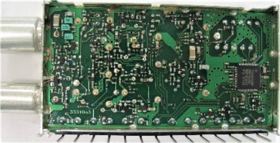
Bottom A-side of the FQD1216CME/IH-Mk5 with far left the TDA9899HN MasterIF and far left the PLT and active loop-through. [RFS PRS Report]
|
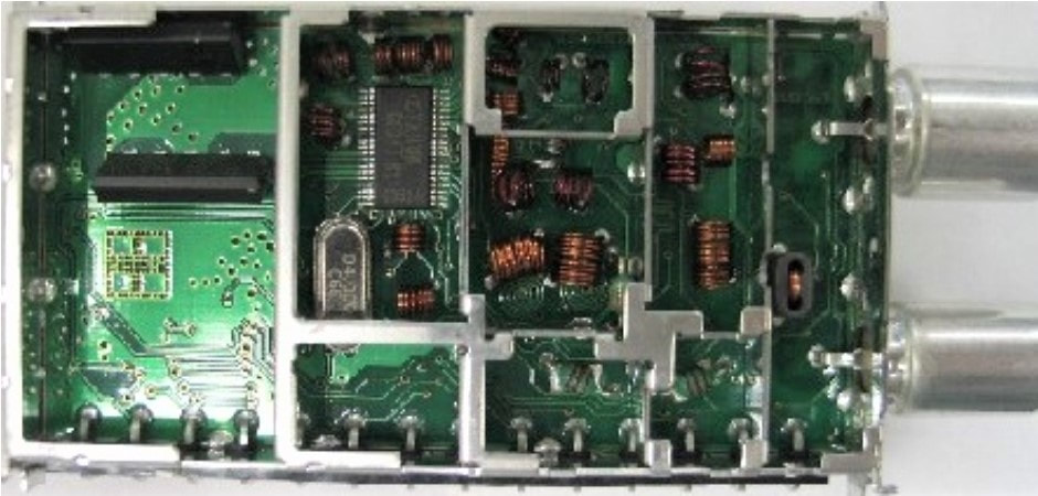
Top B-side picture of the FQD1216CME/IH-Mk5. Most noteworthy are the TSSOP38 MOPLL IC and in the leftmost IF section no longer a DTV SAW. [RFS PRS Report]
|
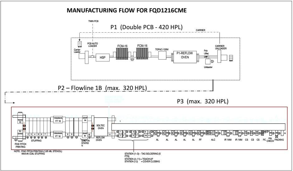
A very instructive picture of the manufacturing flow of the FQD1200CME-Mk5 production in the RFS Batam factory. P1 is the A-side SMD onsertion process. It required only one operator to load and unload the PCB carriers. The carriers then went through HSP (High Speed Printer), FCM (Flexible Comnponent Mounter), the Topaz vision-controlled component mounter (for the HVQFN ICs) and a first reflow oven. As indicated the P1 delivered 420 units per hour (HPL). P2 (B-side component mounting) and P3 (alignment and test) were integrated in a single 320 HPL flow line. P2 required 11 operators of which 8 for component in- and onsertion. The Ekra printer applied the solder paste first. The Yamaha YT-18 did the SSOP IC placement on the B-side. At the snap-in the frame was snapped onto the PCB, followed by the second reflow soldering step. P3 started with 3 stations for soldering the PCB-to-frame tags, followed by visual inspection and touch-up (mostly overflown solder joints) while at station 12 the bottom cover (A-side) was closed. Then followed five RF alignment stations (AL), one fault finding (FF) of tuners that could not be aligned (often due to short circuits of air coils to the frame). ALC was the alignment checker to confirm good tuner performance, before at IF/MM the IF section was verified (no alignment required, but because the MasterIF was new proper demodulation was verified). CS was bottom cover soldering, followed by a final performance check (PC), checking that all pins were straight and packing into the cardboard boxes. In total the P3 required 27 operators. [RFS PRS document FQD1216CME, November 2006]
With this we have reached yet another remarkable milestone: the end of the Philips pinning. Introduced in 1983 with the UV400, this tuner module mechanical standard had established itself as one of the two global references, the other being the Japanese standard. In the 25 years since then hundreds of millions of tuners, frontends and tumods were produced under the 400, 600, 700, 800, 900 and 1200 product families, plus of course all those of the compatible competition (Grundig, Thomson, Temic, Siel, and many more). If we take the 12nc as the timing indicator, below two modules were the last two released using the Philips pinning. Although in tuners the WSP survived, in most other RF functions pinning had almost become a case-by-case solution. In that respect the demise of the Philips pinning was another indicator of the end of an era.
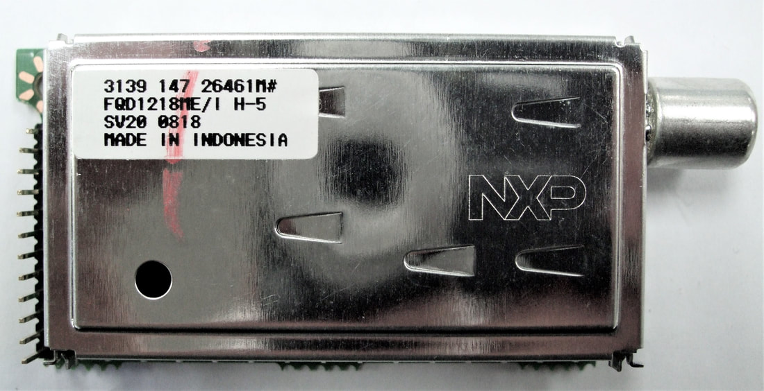
The second last Philips 1200-family module: the FQD1218ME/IH-5. Note that it already no longer uses the typical 1200 Philips pinning, but a - so far unique - series of pins at the long end of the module.
|
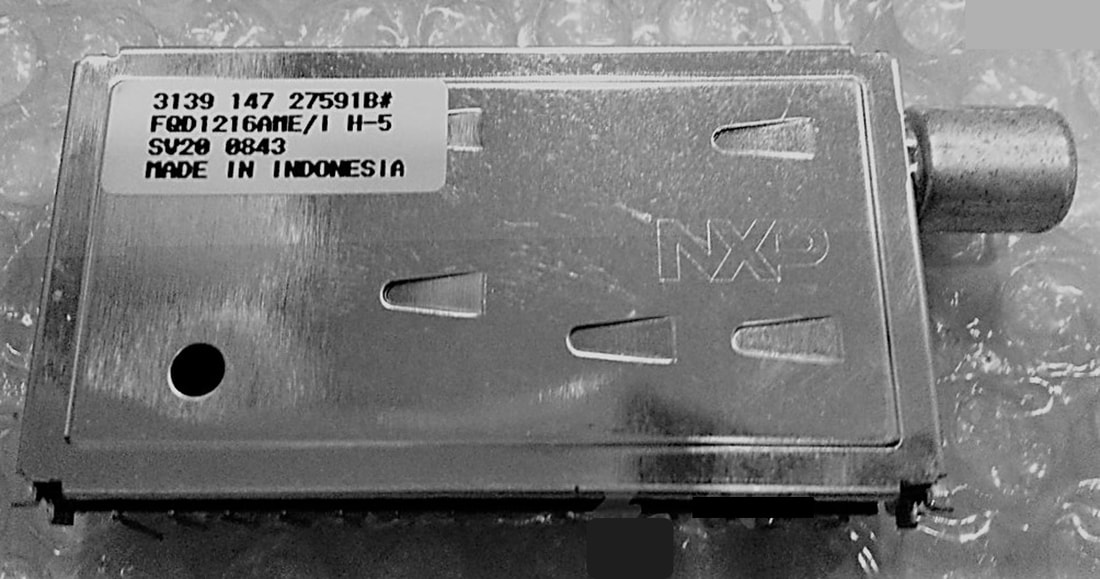
This must be the very last RF module released using the Philips pinning: the FQD1216AME/IH-5 with additional LNA. Release date was probably early 2008, production date of this module was week 43 that year.
|
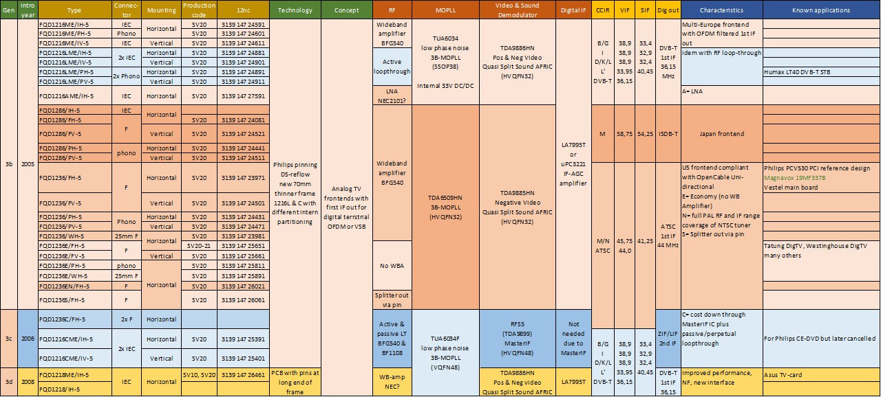
Overview of the Philips FQD1200-Mk5 hybrid front end family. This was the last family of products based on the Philips-pinning. All products were only produced in Batam (SV20).
TD1300, TD1600 and TD1700 OFDM tuners, 2003-2008
Until around 2003 digital television was mainly a satellite (first) and cable application. Terrestrial, off-air digital TV clearly was the slowest of the three, mainly because off-air TV distribution is traditionally a government-driven national service. Satellite TV and cable TV networks, often owned by private companies, are in that sense easier to deploy, much less hindered by government ruling and politics. But around 2003 the digital off-air deployment picked up momentum, driven by two, quite different developments.
- the almost instantaneous switch-over of the TV display technology from CRT to plasma and especially LCD. This quickly pushed the screen size beyond the traditional 29-30" CRT limit, requiring higher picture resolution. In the absence of any practical analog HDTV standard digital MPEG-coded HDTV was the only realistic option. So whereas the MPEG coding was so far used by satellite and cable transmission to squeeze more broadcast channels into a standard channel, with off-air it finally also became a way to carry HDTV signals. (Of course satellite and cable followed suit). For digital off-air the standards were DVB-T (Europe and most of Asia), ATSC (US, Canada), ISDB-T (Japan, Brazil) and DTMB (China). They were based on OFDM, except for the VSB-based ATSC, and from a tuner perspective relatively identical although ATSC was more relaxed on phase noise.
- government decisions on the so-called "Analog switch-off". Maintaining parallel analog and digital broadcast infrastructures is extremely expensive, and many government policy bodies therefore announced their intention to switch off the old analog broadcast. Here the local conditions influenced decisions, mostly depending upon the dominance of off-air TV reception versus the other means. The city of Berlin was the first to switch off end of 2003, followed in 2006 by Luxemburg and the Netherlands. The US announced the switch-off for full power transmitting stations for 2009.
|
As explained in the TD1300-Mk1 section, this first generation off-air tuner was used in what were essentially experimental digital TV sets. Examples are the A10E 28DW6500 and the MG4.1 28DW9625, both widescreen CRT sets from 2001. They both used bolt-on digital TV boards, the A10 with the Philips TD1316L but the MG4 even using an Alps front end! (It seems the MG4 digital board was externally sourced, since it did not contain a single Philips component). The first chassis that had the digital bolt-on as a more structural option was the first LCD chassis LC4 from 2004, still using the TD1300-Mk1. In the meantime this Mk1 family, although not running in very high numbers, was having trouble with its fractional-N PLL TDA6651, which showed some fundamental performance issues requiring a full redesign. The TD(M)1300A(L)-Mk2 was therefore essentially a change of MOPLL, from the Philips to the Infineon TUA6403. Otherwise the function remained identical: optional Motorola modulator (M) and RF loop-through (L). Apart from the new modulator the main changes were the default addition of a wideband LNA (A) for better input matching, CSO and CTB, while the digital IF AGC amplifier moved from the 16-pins the Sanyo LA7793 to the smaller 8-pins LA7795. The Mk2 continued to use the 65mm WSP frame. With the family two new types were introduced that reflected an application trend: the TD1314 real off-air tuner that only covered the classical VHF-III and UHF off-air bands, not the hyperband in between. The TD1344 was a UHF-only tuner for the UK. The fact that the Tuner group was willing to develop this always problematic type - it required a full 3B MOPLL IC of which only one band was used - indicates the importance of the UK market, as one of the first to push for the analog switch-off. And like for Digital Cable, see above, also Digital off-air had its pair of tuners for the "Twin Tuner" application, with the RF signal passing from the first tuner to the second tuner via pins and a short track on the PCB.
|
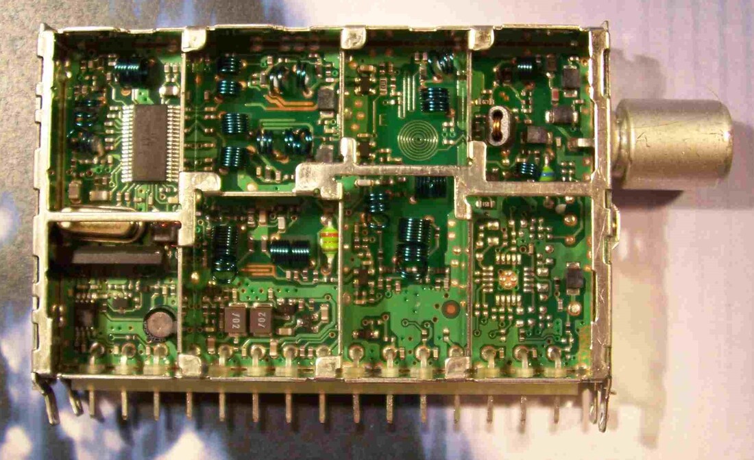
The Philips TD1316AS/IVP-2 DVB-T off-air tuner. Upper right the loop-through splitter trafo is visible, the RF output is on pin 3. The space for the QFP20 modulator IC is visible lower right. Upper left the SSOP38 TUA6403, below it the X-tal, SAW filter and lower left the 8-pin LA7795.
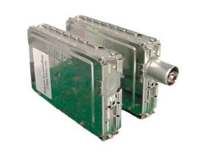
The TD1316A/SRV-2 (left) and TD1316AS/IVP-2 (right) that were used in the "Twin Tuner" concept, with the RF loop-through signal via pins and the PCB.
|
There are no traces of the intial Mk2 being actually used, probably at least partly due to the fact that is was a rather large module. Because by now, 2004-2005, TV sets started to be prepared for both analogue and digital TV reception, set makers demanded pin compatible UV1300 analogue and TD1300 digital tuners that could be replaced depending upon the set features. Therefore the initial 65mm TD1300A-Mk2 was quickly followed by the 50mm TD1300AF-Mk2 in the standard WSP frame. The AF-Mk2 was electrically completely identical to the A-Mk2 except for the fact that the modulator option was dropped. It still contained the optional loop-through, the SAW plus AGC amplifier as well as the 33V DC/DC-converter and the buffered 4MHz X-tal output. The TD1300AF size would quickly become the standard size for the digital off-air tuners.
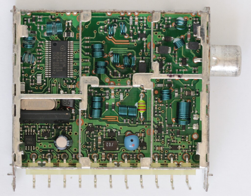
The Philips TD1316AF/IHP-Mk2 in the new 50mm WSP form factor. Apart from the deleted modulator the electrical content is identical to the original 65mm TD1316-MK2. [Henk van der Wijst collection]
|
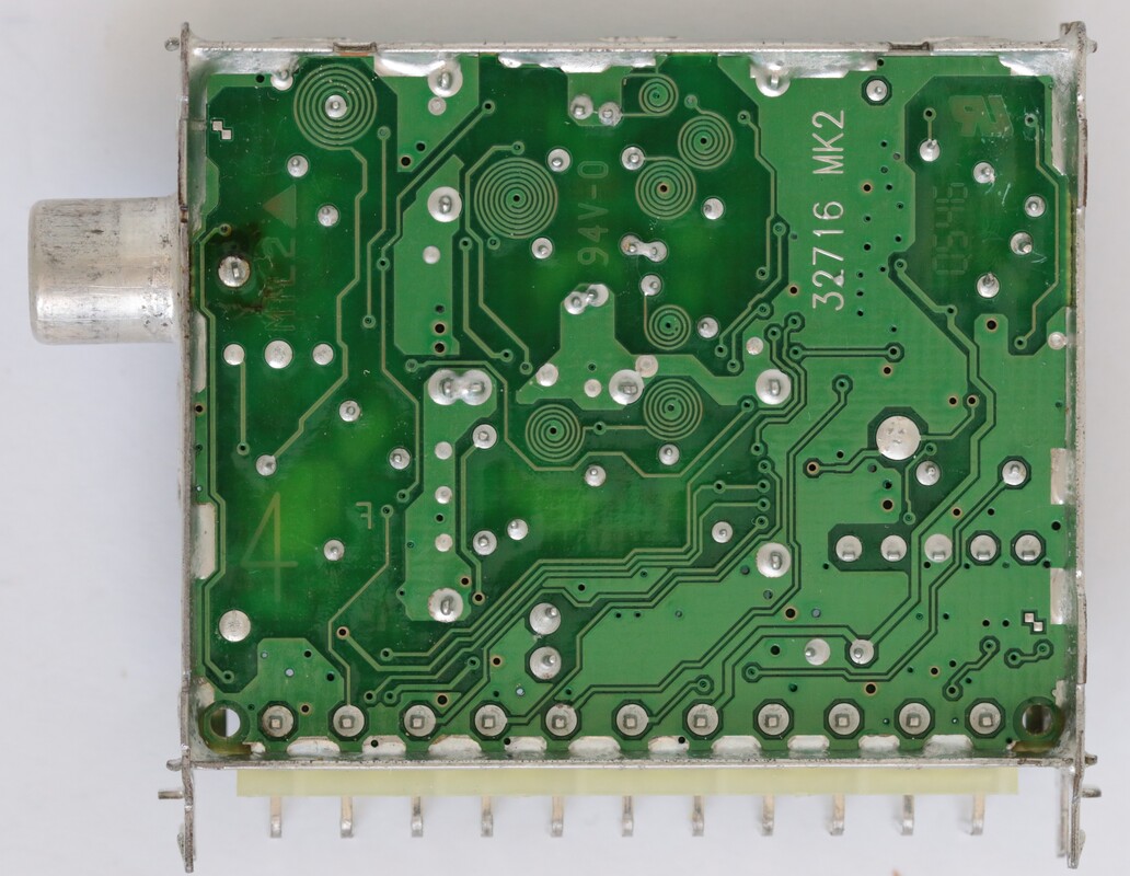
Wave soldering side of the Philips TD1316AF/IHP-Mk2. For good RF performance the number of printed coils is clearly lower than in standard UV1300-MK2 or Mk3 tuners. [Henk van der Wijst collection]
|
|
The TD1316A(L)F-Mk2 was the first DVB-T tuner to become part of the basic chassis design, not as a bolt-on function. The Jaguar chassis launched in 2004 had the TD1316AF as standard digital tuner next to the UV1318 that has been presented already. Interestingly, as shown in the UV1318 section, in case of single tuner configurations of the Jaguar chassis the TD1316AF was the only tuner, not an analogue version! From 2004 to 2007 the TD1316AF was on all versions of the Jaguar platform for plasma, LCD and rear projection displays, while in 2007 it was again introduced on the LC7 LCD chassis. As such the Mk2 marked the start of the turning point from pure analogue to hybrid TV.
|
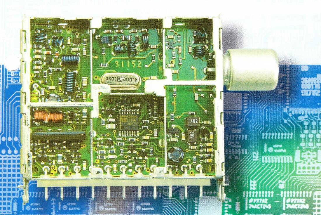
Picture of the Philips TD1344F/IV-2 UHF-only tuner for the UK. It was a single band tuner with a discrete MO (upper left) and PLL IC. The input amplifier was deleted, while the DC/DC converter moved to the lower right compartment. [Philips BL Tuners leaflet TD1300-Mk2, 2004]
|
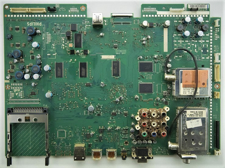
The TD1316AF/PHP-2 as main hybrid tuner next to the UV1318ST/AIHN-3 analogue tuner with loop-through. The chassis is the Full Jaguar FJ3.0 42PF9731 from 2005. Next to the TD tuner are two channel decoders, one OFDM TDA10046 and one QAM TDA10023.
|
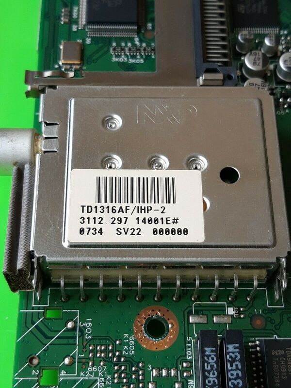
The NXP TD1316AF/IHP-Mk2 on the 2007 Philips LC7 LCD chassis. Below the tuner the two analogue TV sound and video SAW filters are visible.
|
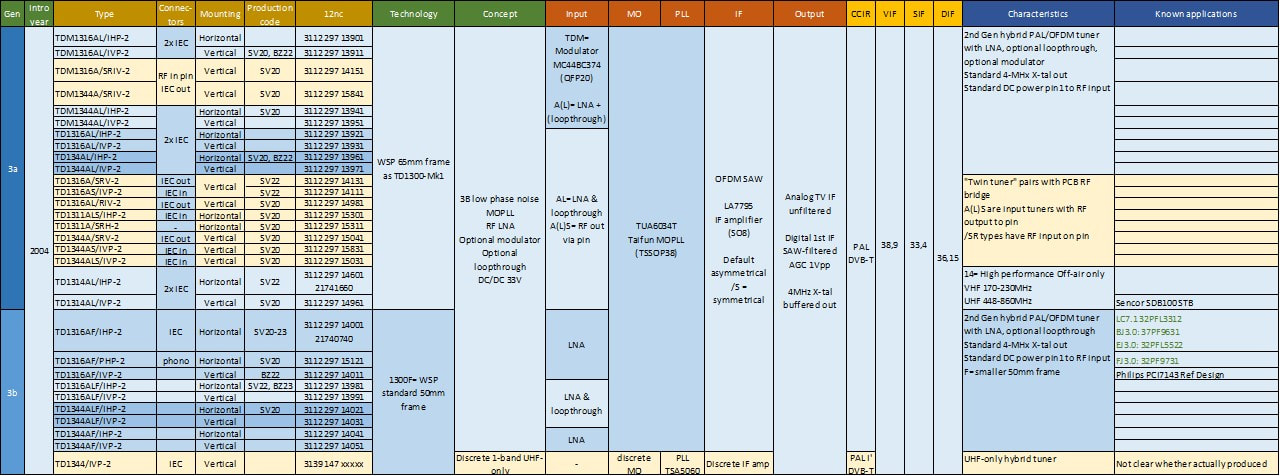
Overview of the Philips TD(M)1300-Mk2 digital off-air (DVB-T) tuners. From the column "Known applications" it is clear that only two models were used internally Philips, all others were for the external market. All modules were produced in Batam (SV2x), with some high runners later also in Suzhou (BZ2x).
Until the start of the TD1300-Mk2 with one or two exceptions all Philips digital off-air tuners were for DVB-T, mainly due to the slow developments of ATSC on the US market and the difficulty to have American set makers decide for a European supplier. However, with the new Philips TV policy to develop hybrid TV chassis, a US tuner solution was required. So, for the first time since the 1998 TD1536 a dedicated ATSC tuner was developed. However, for a standard US TV the requirement was to be able to receive both off-air and open cable channels. In the US the Open Cable alliance had launched a set of requirements for cable TV reception that would standardize cable reception without the need for using a STB. In practice the Open Cable requirements came down to proper impedance matching across the entire band and minimal CSO/CTB requirements. This required a wideband input stage of the tuner, to guarantee proper VSWR also at channels not being viewed. (Remember that for the standard 3-band tuner concept the VSWR is only guaranteed at the wanted channel through proper tuned matching, the VSWR at all other channels is not specified). The TD1336OZ tuner had the following main characteristics:
- because the ATSC requirements are lower with respect to phase noise, the 1336 switched to the cheaper Philips Semiconductors TDA6509 MOPLL, similar to the FQD1200 approach. All tuners had wideband AGC (G) and DC power for an antenna amplifier on pin1 (P).
- the Open Cable requirement was met through a wideband amplifier, followed by a power splitter.
- the second Open Cable requirement was the provision of an Out-of-Band (OoB, option O) receiver path. For this a low pass filtered RF output to pin3 was added, covering the 70-130MHz band.
- the splitter output could go either to a regular second connector (option L) or, not seen earlier on Philips tuners, via a mini phono connector on the side of the tuner (option Z).
- it was the last TD1300 to use the 65mm long frame, mainly to allow the phono connector mounting.
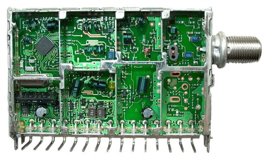
Interior B-side view of the Philips TD1336O/FGHP. The three Cu-lined
mounting holes for the solder tags of the sideways mini-phono connector are clearly visible in the lower right compartment.
|
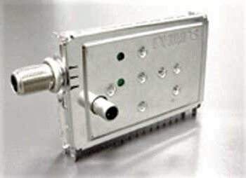
Low resolution but unique picture of the TD1336OZ/FGVP with the side mini-phono connector for the RF loop-through output.
|
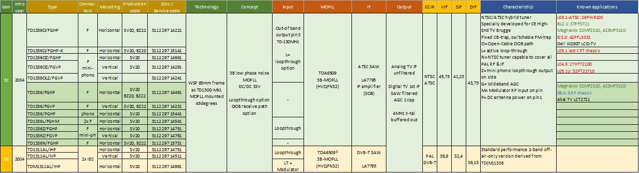
Overview of the Philips TD1336 digital off-air (ATSC) tuners. Effectively they were a transition from the 65mm Mk2 and the 50mm Mk3 family. Size-wise they belonged still to the Mk2, component-wise they were the first Mk3. Since specifically developed for Philips TV they were used in all Philips US chassis.
The TD1300-Mk3, launched in 2006, is a bit of an oddity. Comparison of the TD1316AF/IHP-2 and TD1316AF/IHP-3 shows they are 99% identical, in terms of mechanics, component type and placement and lay-out. There is only one component added in the input circuit. In the old tuner days this would never have been sufficient change to justify a new generation name. But times were changing, with many old hands forced to leave after the re-merger of the BLs RF Solutions and Tuners, and the naming convention, which had been followed quite rigorously and consistently since the UV400, was being modified much more creatively. So, apart from the unclear Mk3 designation more surprising defintions emerged:
- the 1600 generarion was introduced. This was in all aspects identical to the 1300, with the exception of a 2mm mounting hole that was added in the space between the two frontal RF connectors. Again, in the old days a hole in a frame would never have been accepted as reason for a generation change.
- around the same time the TD1700 was introduced, which re-used the 1600 frame hole and additionally offered a 2mm higher stand-off with longer mounted tags and pins. Same story. This allowed to place SMDs between the tuner and the PCB it was mounted on, which was especially used in the Philips Hotel TV digital boards. It also deleted the digital TV IF path with the OFDM SAW and Sanyo AGC amplifier. The IF functionality could be deleted because Philips TVs started using the Semiconductors TDA9899 MasterIF IC that no longer required pre-filtered IF inputs. In effect the TD1716 was developed exclusively for Philips high-end TV in Brugge, which used if for their flagship LC7 and TV520 platform, on the latter covering the 2007 and 2008 Q522, Q523 and Q528 chassis.
|
In terms of the application one of the developments was that under pressure of the DOCSIS developments (DOCSIS3.0 was emerging around this time) free analogue cable was disappearing, being entirely replaced by conditional access controlled cable reception. This despite the Open Cable efforts to counter this. At least in Europe cable reception therefore always required a STB, and the need for cable-ready tuners in TV sets was disappearing. In other words, after 25 years of hyperband cable tuners since the early 1980s, off-air-only tuners emerged again. After a first TD1314-Mk2, the new naming converged on TD1311 from the Mk3 onward. These tuners only covered the VHF-III off air and UHF channels. At the same time the Mk3 family also saw the TD1318 type, the 18 indicating high performance full band. The high performance was probably identical to that obtained with the UV1318-Mk4 and due to the introduction of the BF1212 UHF MOSFET, providing a serious UHF NF improvement.
|
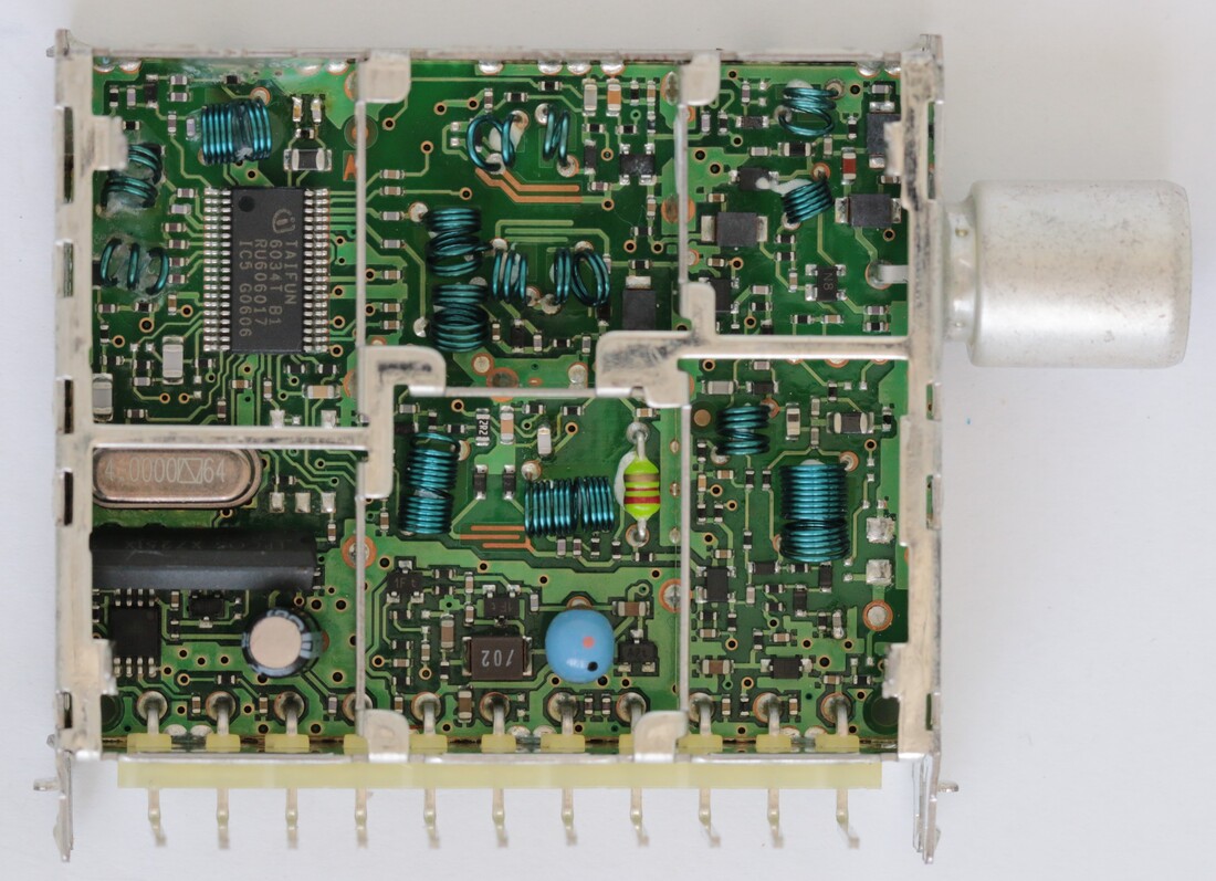
The Philips/NXP TD1318AF/IHP-3. Visible differences with the TD1316-Mk2 are minimal. [Henk van der Wijst collection]
|
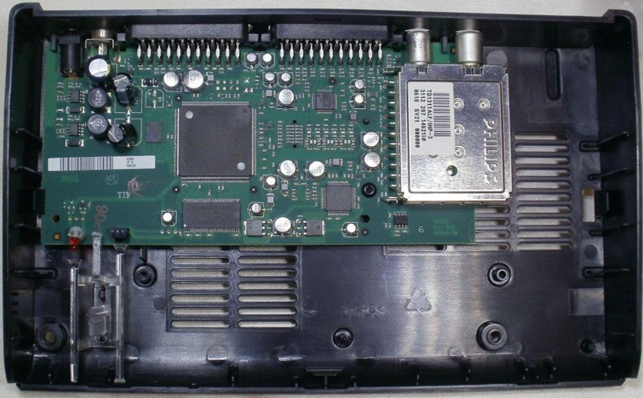
One of the first applications of the new off-air only DVB-T tuners, the TD1311AF/IHP-3 in the Philips DTR300 DVB-T STB. [Radiomuseum.org]
|
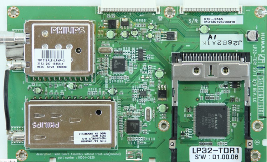
In the years before the actual analogue switch-off many devices had to be hybrid, using multiple tuners. Here a Humax LT40 DVB-T STB from 2006, containing a TD1316ALF/LIHP-3 (the first L indicating the RF Loop-through, the second L a long IEC input connector) and an FQ1216ME/IH-5 analogue frontend.
|
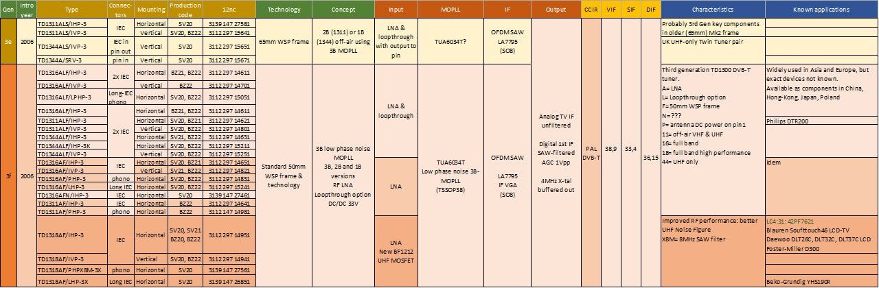
Overview of the Philips/NXP TD1300-Mk3 family of digital off-air tuners. This family was very successful, and ran in high volumes, but the majority of customers were Asian cable modem and STB makers that are difficult to trace back. After initial volume ramp-up in Batam (SV20) most products were transferred to Suzhou for volume production (BZ22).
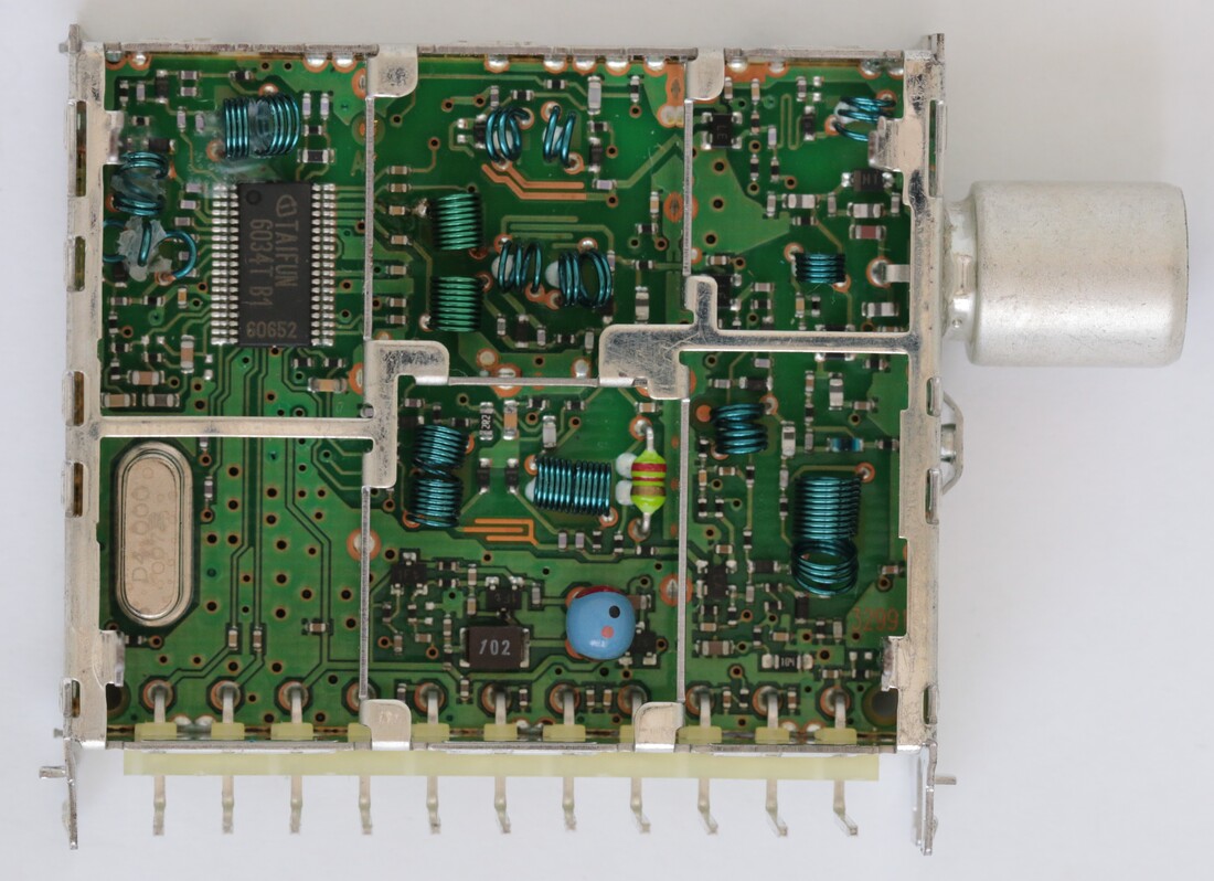
The Philips/NXP TD1716AF/IHXP-3. Note in the lower left compartment the deletion of the SAW filter and Sanyo AGC amplifier. The X indicates it has no SAW-filter and IF amplifier, a Philips TV specific product. Below the RF connector the protrusion for the mounting hole is also visible. [Henk van der Wijst collection]
Another innovation, this time in the mechanical domain, that was introduced in the Mk3 generation was the vertical (if we take a horizontally mounted tuner as reference) or orthogonal (if we take the A-side cover as reference) RF connector. It was introduced with the TD1716F-Mk3 on the special request of Philips TV. Using such a construction the tuner no longer needed be at the periphery of the Small Signal Panel, but could be placed anywhere on the board, providing much more design freedom. For vertical IEC connectors the suffix was B, for vertical F connectors N. The concept became more dominant in the next Mk4 generation, and was introduced for full mechanical compatibility with the UV1300-Mk5 and HD1800 hybrid tuners. The first application was again the Philips TV520 platform, the Q522, Q523 and Q528 chassis.
The tuners with the vertical connector marked the beginning of yet another (internal) development: transfer of the TD product responsibility from Eindhoven to Singapore. Initially only the tuners with vertical connector had Singapore 12nc's, but within the next generation TD-Mk4 already half of the products had the same origin. |
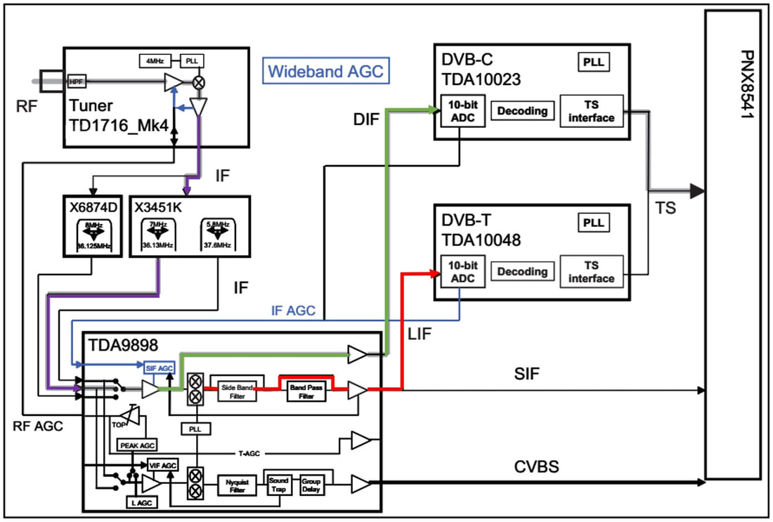
Block diagram of the Philips Q522 chassis, using the TD1716-Mk3/Mk4, the MasterIF TDA9898, DVB-T and -C channel decoders and the PNX8541 digital video one-chip. The red signal path for DVB-T shows the 2nd IF down-conversion and filtering in the MasterIF. [Philips Q522 Service Manual, 2008]
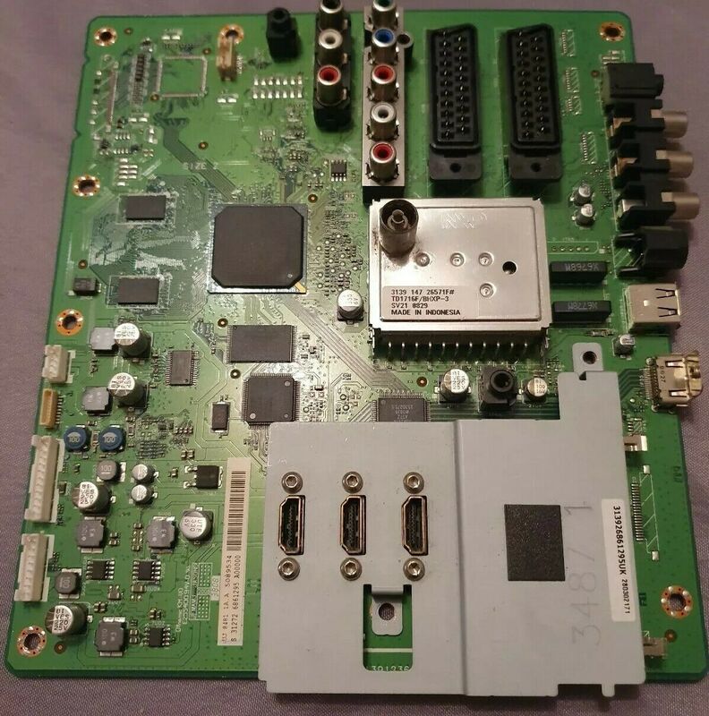
One of the first applications of the new vertical connector concept, here the NXP TD1716F/BHXP-3 on a Philips TV520 Q522 chassis.
|
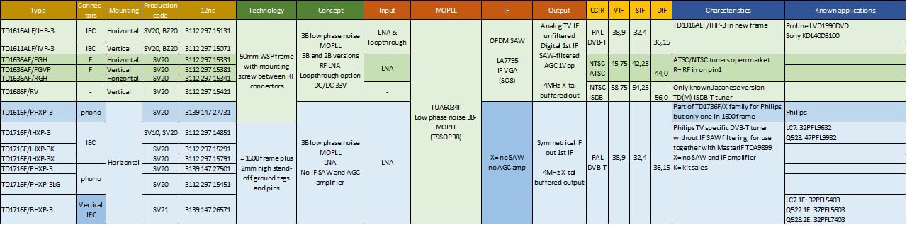
Overview of the Philips/NXP TD1600-Mk3 and TD1700-Mk3 families of digital off-air tuners. Both the 1600 and 1700 were minor mechanical changes compared to the TD1300, although the TD1700/X was specifically for Philips TV and no longer had the digital SAW and VGA.
The last generation in this series of digital off-air tuners is the Mk4. Like with the previous changes of generation, the differences were not huge, but mostly the continuation of trends that had started already. For the Mk4 these changes were:
- Focus on real off-air tuners for VHF-III and UHF (the TD1311/1611) or UHF-only (TD1344/1644). Diversity of these models was reduced to vertical vs. horizontal mounting, all tuners were standard ALF, so with LNA, loop-through and short 50mm frame. Only one TD1316 full band model.
- These PAL tuners switched from the Infineon TUA6034 to the NXP TDA6651, which was now the cheapest MOPLL available, and still high-performance based on its fractional-N dividers. NTSC tuners continued with the TDA6509. At the same time the Sanyo LA7795 IF AGC amplifier was replaced by a discrete transistor solution.
- For Philips High End TV Brugge the TD1700 without the digital-IF SAW filter was continued, with the TD1716 and TD1736-Mk4. The Open Cable requirement was disappaering and requested on only one model. For the US versions of the LC8 chassis the off-air only TD1331 was designed, but all TD1736's remained full-band.
- The TD1636 was the tuner for the open US ATSC market, and very successful with many US LCD set makers. It seems that several customer-specific versions were made too. The TD1636 was the first TD tuner designed in Singapore.
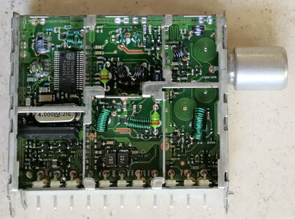
A tuner sample with no label, but likely the TD1316F/IVP-4. Note the TDA6651 MOPLL and the absence of the Sanyo AGC amplifier. [Pieter Hooijmans collection]
|
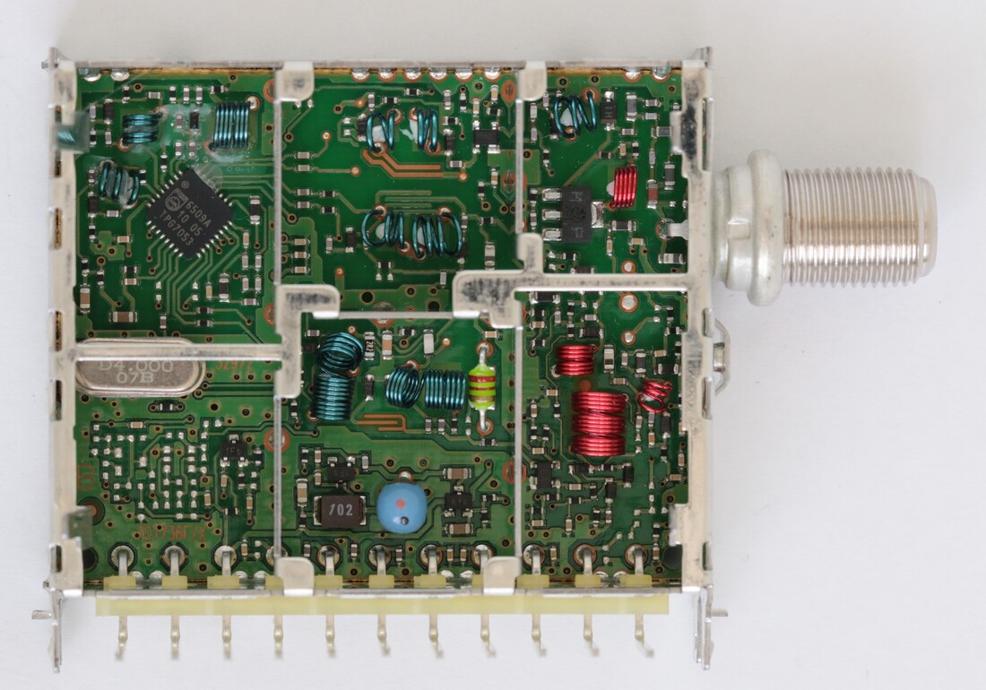
The NXP TD1736F/FHFXP NTSC tuner. Like all HVQFN ICs the TDA6509 has been rotated 45 degrees for optimal soldering. Note the very thick LNA transistor upper right. [Henk van der Wijst collection]
|
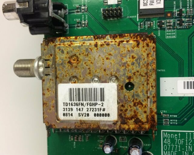
An NXP TD1636FN/FGHP-2 that has survived severely humid environmental conditions in a Westinghouse SK32 LCD TV. Despite the rusted cover tuner performance was guaranteed!
|
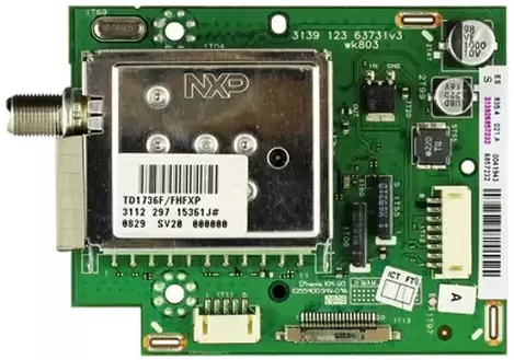
The same TD1736 as above was used for a number of years in Philips Hotel-TV sets like this 22HFL5530. Especially this application used the 1700 family with the 2,2mm vertical stand-off from the PCB, such that SMD components could be mounted underneath the tuner module.
|
|
The TD1300/1600/1700-Mk4 generation ended a series of developments of the off-air tuners that was most remarkable by the quick succession of generations. Where normal tuner generations easily lived 3 to sometimes 4 years, the TD tuners saw four generations in four years. At the same time it is fair to say that the changes between generations were much lower, if not to say minimal. So it seems that some generation changes were more marketing than technology. It should also be remembered that real TD sales only took off in 2003, with minimal quanties up to then. In 2005 and 2006, with the analogue switch-off starting in multiple countries, the TD1300 family became the fastest growing product segment within the BL, with 39Mio€ sales to the STB segment and 23Mio€ to the TV. With these quantities the TD segment had grown to become the single biggest family, generating 35% of the BL sales. A major business success and the result of an analog-to-digital migration that started 10 years earlier.
|
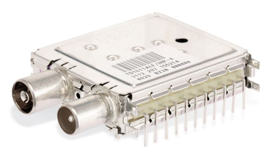
The TD1611ALF/IHP-4 off-air tuner with LNA and Loop-through. The mounting hole between the RF connectors, identifying the 1600 family, is clearly visible.
|
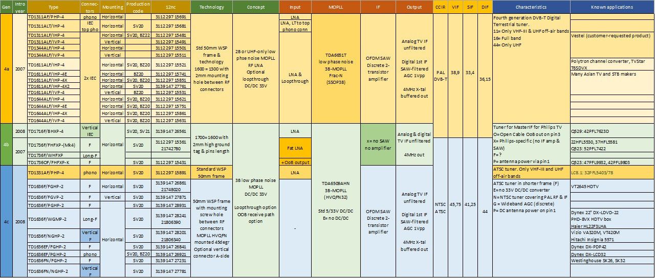
Overview of the 4th Generation Philips off-air tuners. Although it still contained some TD1300, the standard external market family became the TD1600 while Philips internally used the TD1700. Especially the TD1636 ATSC tuner was very successful in the US.
Philips Semiconductors becomes NXP, 2005-2008
Since his coming to power as the new president of Philips in 2002, Gerard Kleisterlee had been focussing on only one thing: re-establish the trust in Philips financial performance. His single-biggest objective was to have an as stable as possible Philips share. Growth and entering or playing in emerging markets were always secondary at best, and allowed as long is the share price stability was not endangered. Kleisterlee therefofre quickly fell in love with the single remaining non-consumer business within Philips: Medical Systems (PMS). This Product Division delivered roughly 20% of the Philips sales, 5,9Bio€ of the in total 31,1Bio€ in 2004. PMS was active in selling large equipment (e.g. X-ray and Magnetic Resonance Imagers) to hospitals, including the installation, service and data management contracts. In contrast to the Consumer Electronics and Semiconductors divisions, which were playing in highly competitive and cyclic markets, PMS was very stable due to its long-term contracts. Philips was globally number 3 behind General Electric and Siemens, both much larger, and business was tough, with barely 0,6% Income from Operation (IFO) in 2004. But that did not matter in the eyes of Kleisterlee, because a predictably stable and low IFO was much better than an unpredictable (high or low) IFO from for example Lighting (13,5% in 2004) and Semiconductors (8,5% that same year). Because, fair enough, Semiconductors had from 2001-2003 been making losses of in total 1,6Bio€.
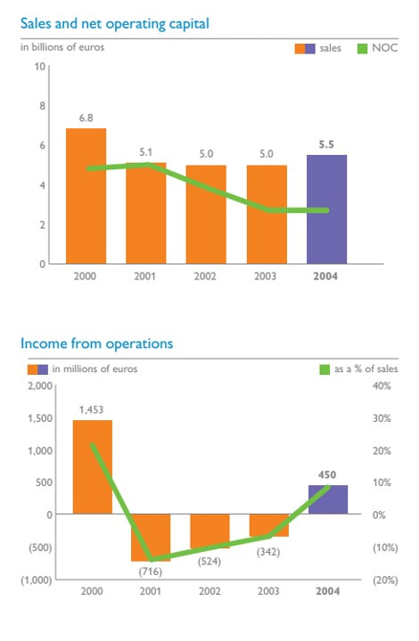
The financial performance of Philips Semiconductors from its record year 2000 through the bursting internet bubble years till 2004. [Philips 2004 Annual Report]
|
So, around the time that the above mentioned 2004 Annual Report was presented (May 2005) it was decided in the Board of Management that Philips no longer wanted to keep its Semiconductor activities, following Siemens (which had spun out its semiconductors to Infineon in 1999) and Motorola (which had spun off its discrete semiconductors as ON Semi in 1999 and did the same with the IC business as Freescale in 2004). In 2001 Kleisterlee had promoted Scott McGregor, until then head of the Emerging Business Unit of Semiconductors, to become the Division Head. Which he did without much exposure and almost at arms length, leaving most decisions to the next level. In 2004 McGregor resigned, formally because of his family, but in reality to become the president of Broadcom that same year. (Non-compete clauses obviously don't apply at that level). He was replaced by Frans van Houten, son of a former Philips CTO and considered member of the larger Philips clan. The intention was that van Houten, at that moment one of the shared managers of Consumer Electronics, would use his role as head of a PD as last test case before becoming Philips president and successor of Kleisterlee. To give him sufficient challenges he got the asignment from the Board to "solve" the Semiconductors problem. In 2005 therefore Project Dolphin started, exploring a (partial) merger with Infineon, where multiple scenarios were on the table. The discussions eventually focused on the Mobile Phones business of both companies, which were stuggeling with high investments and declining market shares. By the end a JV of the Philips-Infineon Mobile businesses was worked out in detail but finally blew, because van Houten and his Infineon counterpart Wolfgang Ziebarth could not agree on who would become the CEO. (Infineon, which was loss-making in 2005 and 2006, thereupon spun out its memory business as Qimonda, which went bankrupt in 2009).
|
|
After the failure of the Infineon merger, efforts were concentrating on bringing Semiconductors to the stock exchange - as Philips would do later with its Lighting business - but then van Houten saw the light (as he explained): private equity. The idea was that PE would come much faster with money to invest and re-structure than shareholders of a public company, and that there would be much more freedom to operate when no quarterly public reporting was required. Both assumptions quickly turned out to be extremely naive. But then it was too late: on August 30, 2006 in an unused U-bahn station in Berlin the new company NXP was launched in the presence of its entire leadership team. The next day it was publicly announced at the Internationale Funk Ausstellung (IFA). The company slogan was "Vibrant Media", referring to the Nexperia SoC platforms. In a classical leveraged buy-out the PE companies Kohlberg Kravis Roberts (KKR), Bain Capital, Silver Lake, Apax, and AlpInvest obtained 80,1% of the shares for 3,4Bio€ cash (that went to Philips) and 4.0Bio€ debt (for the new company, also to pay Philips), equivalent to a total company value of 8,4Bio€. At roughly 1,5 times the sales this was a good value for the business, but the leveraged buy-out loaded the new company under a total debt of 4,5Bio€. So the greed of Philips didn't help its offspring to a healthy start, crumbling under around 600Mio€ interest per year. And instead of the investments van Houten had dreamed of, almost immediately major cost cutting and clean up activities started. Money for investments was not available since the interest had to be paid first. At its launch in 2006, NXP had 5Bio€ sales: 1,6Bio Mobile & Personal (BU M&P: mobile phones, connectivity, mobile speakers), 0,9 Home (TV, STB, Tuners), 0,9 Automotive and Identification, 1,3 MultiMarket Solutions (discretes, logic, microcontrollers, interfaces) and 0,2 Others (including manufacturing services to thirds). Overall profitability was 150Mio€ or 3%.
|

Frans van Houten at the NXP launching event, August 30 2006 in Berlin.
The new company logo, nicely colourful as opposed to most tech company logos. The "Founded by Philips" was allowed to be used five years, but effectively dropped very quickly.
|

The main products of the BU Home as listed early 2007. Note the Silicon Tuner!
|
But not only Philips had been naive in its expectations of the deal, the same was true for KKR and its partners who had no experience whatsoever with the semiconductor world. An in-depth due dilligence was never done! Immediately after the spin-out they were all over the businesses to assess the real situation, only to find out that the sales predictions, which had been inflated to unprecedented levels under the pressure of McKinsey, were totally unrealistic. On the contrary, especially the Mobile and Home businesses, with their very high investments in big SoC platforms and the associated software, were draining money. Already by November 2006, so barely three months after the deal, Project Saturn started, targeting the acquisition of the Texas-based Silicon Labs CMOS single-chip cellular phone business. The BU Mobile management at the time was still convinced that smart phones would remain only a 10-15% niche of the mobile phone market, and that the majority of phones would be cheap, highly integrated low to mid end phones. Since NXP had no internal RF-CMOS solution, the SiLabs acquisition was deemed a necessary addition. In February the deal was struck, based on a 285Mio$ cash acquisition. However, the aim of the deal, as driven by KKR, was not to strengthen the BU M&P internally, but to better prepare it for sale! Almost immediately after completing the integration of SiLabs, on April 10 2008, it was announced that the Mobile Phone business would be sold to French/Italian ST Microelectronics into a 20-80 JV structure plus 1,55Bio$ cash. The deal of what became ST-NXP Wireless was closed in record time by August, thus saving NXP from impending bankruptcy. In effect this was a severe blow to the Going Digital strategy of still CTO Theo Claassen, the burden of the heavy SoC investments now landing entirely on the shoulders of the already loss-making BU Home. The Going Digital SoC strategy had already received another blow when NXP announced early 2007 that it would exit the Crolles alliance for advanced CMOS development, intending to rely entirely on foundries like TSMC, UMC and Global Foundries. In parallel it started a disastrous "Fab Light" strategy, successively closing the Boeblingen (Germany, 2007), Fishkill (New York, 2008), Hamburg IC-fab and Nijmegen ICN4 and ICN6 silicon fabs (2009). Also for Frans van Houten the spin out of the mobile business was a very serious setback, shattering his dreams of becoming a Top3 semiconductor player. But his Philips bosses were happy, because they got rid of the volatile semiconductor business and obtained some 6,5Bio cash.
|
RF Solutions becomes NXP, 2005-2007
Where was the RF Solutions tuner business in all this? As explained earlier, after a short split-up into BL RF Solutions and BL Tuners during 2002 and 2003, since January 1, 2004 the businesses were again combined into a single BL RF Solutions, which still found itself in Corporate Investments, as it was now called. The moment RF Solutions was created it started a strategic analysis of where to go, beyond the classical tuner and satellite modules. One of the conclusions was that portable multi-radio solutions were a good direction. With new emerging standards like IEEE 802.11 WiFi, GPS navigation the need for good RF solutions in small portable solutions would be increasing. This is where the typical RF knowledge of Tuners and RF Solutions could help to create small, good and cost effective solutions. A second domain was TV reception in small form factors.
|
A first step into the latter field was a PC Card DVB-T tuner module, the PCD2016. PC Card was the development of the 1990 PCMCIA interface, introduced by SanDisk for external memory modules in especially laptops and Personal Digital Assistants (PDA). Based on the same architecture a DVB-T receiver module for the new laptop mini-PCI interface was developed, the PDM2016. Although none of these products ran in any siginificant numbers, they were the trigger for technology development driven by much smaller units. Especially the minimal thickness of a few mm required different key components, inductors and shielding technology.
The Philips PDM2016 mini-PCI DVB-T NIM module. It is essentially a low profile TD1300-Mk2 followed by the Zarlink MT352 OFDM channel decoder. The RF input is upper right, the first shielded section contains ESD protection and an LNA, the 2nd section the VHF-III and UHF tuned BPF, the 3rd section the flat 4MHz crystal on the right and the Infineon TUA6034 MOPLL on the left, left of it the SAW filter and far left the IF AGC. Dimensions of the module are 66 x 51 x 5mm while power consumption was 0,8W. [RF Solutions Mini PCI DTV NIM, 2003]
|
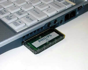
The Philips PCD2016 DVB-T and ATSC tuner module for the PC Card interface. The RF frontend part with the antenna stuck out for proper reception and handling. [RF Solutions, 2003]
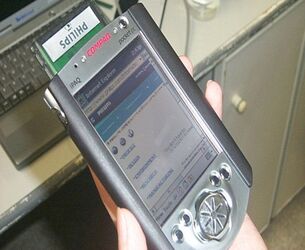
The PCD2016 in a Compaq PDA.
|
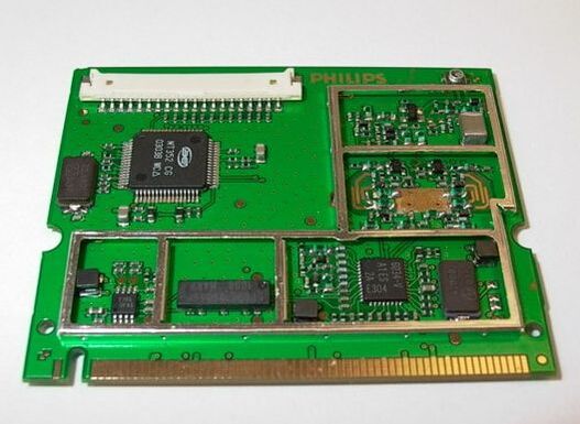
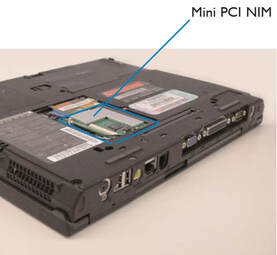
The year 2004 finally saw financial recovery with a modest growth and 15% profit. Although UV1300 analog tuner volumes kept declining, the FQ1200 MultiMedia frontends were are their point of maximum sales, some 45Mio€, while the CD1300 digital cable and TD1300 digital terrestrial tuners were finally taking off. Satellite module sales, in contrast, were by now rapidly declining due to the fully integrated tuner-on-the-board and in 2005 the last 2 Mio units were sold. The portable tuners were taking off very slowly, with the first products in 2005. Most importantly, however, profitability was back at a healthy 7% per year, pushing the BL out of the immediate danger zone.
In 2004, after the re-merger of the two BLs, it was announced to the RFS organisation that it was the intention to sell the Batam factory, which was considered the biggest liability with its 1500 employees. As already shown over the last chapters, owning large factories was increasingly considered as highly undesirable within Philips at large. Bad for Net Operating Capital (NOC), Return on Net Assets (RONA) and other financial parameters, and furthermore expensive and difficult to restructure. Which is all true, but at the same time unfair to the highly efficient and world class operation of the Tuner Batam factory. Nevertheless the effort to spin the factory off continued, which turned out to be very difficult and all three serious candidates in the end declined. At this point discussions started with Philips Semiconductors, where I myself provided the connection between RFS, where I had worked for 7 years and which I knew inside and out, and the Communication Cluster of Mario Rivas, which I had joined in 2003 as Vice President for the RF Program. There were several arguments for such a move:
In 2004, after the re-merger of the two BLs, it was announced to the RFS organisation that it was the intention to sell the Batam factory, which was considered the biggest liability with its 1500 employees. As already shown over the last chapters, owning large factories was increasingly considered as highly undesirable within Philips at large. Bad for Net Operating Capital (NOC), Return on Net Assets (RONA) and other financial parameters, and furthermore expensive and difficult to restructure. Which is all true, but at the same time unfair to the highly efficient and world class operation of the Tuner Batam factory. Nevertheless the effort to spin the factory off continued, which turned out to be very difficult and all three serious candidates in the end declined. At this point discussions started with Philips Semiconductors, where I myself provided the connection between RFS, where I had worked for 7 years and which I knew inside and out, and the Communication Cluster of Mario Rivas, which I had joined in 2003 as Vice President for the RF Program. There were several arguments for such a move:
- Increasingly RF modules were used for new RF functions, like Wifi, Bluetooth, GPS, TV-on-Mobile, WiMax and the likes. This was clearly the expertise of RF Solutions: high volume RF consumer modules. Most relevant for Semiconductors was the involvement of RFS in the Nokia TV-on-Mobile module (which will be discussed in the next section);
- RF Solutions could complete the RF element of integral reference designs for TV, STB and communication solutions. Although this happened regularly, it was never structural, and on the negative side Semiconductors sometimes used competition tuners in their reference designs and publicity material;
- With the emerging Silicon Tuner there was a need to converge as much as possible on a single market strategy;
- RF Solutions with its 120-150Mio€ business could contribute to the Mario Rivas Communications ambition of reaching 1Bio€ RF sales.
|
Early 2005 Mario Rivas decided that he liked the idea, and was interested to receive RF Solutions within his Communications Cluster. This was communicated to Corporate Investments, which was obviously happy to see one of its problems solved. But then the internal politics within Semiconductors started. The Consumer Cluster, led by Leon Husson, now also claimed the business, based on the argument that the main products of RFS were still TV tuners, and that the synergy with the Caen BL TV Frontends (point 3. in the list above) was most important. It took more than a year of wrestling, Mario Rivas had in the meantime left the company for private reasons, and so Consumer won the battle: per January 2006 RF Solutions was moved to what was now called the Business Unit Home. Within a year Philips Semiconductors became NXP, and so that is how, 55 years after the first tuner was built for the TX400, the tuner business was no longer within Philips. As soon as the old stock was depleted the module covers thus changed from Philips to NXP.
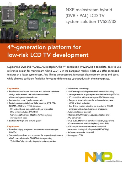
Immediately after becoming part of Semiconductors/NXP the tuner modules were structurally used in platform promotion: here the TD1716F as part of the TV522 LCD platform based on the PNX8541. [NXP, 2007]
|
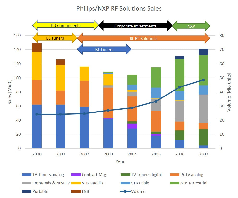
Sales of the Philips/NXP Tuners and RF Solutions businesses, split over the different product segments. The arrows at the top indicate the organisation structure over time; at the top the PD, below it the BL.
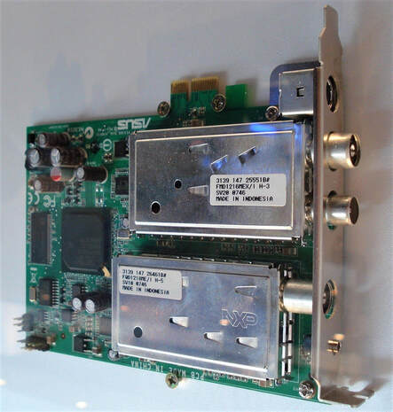
On an ASUS TV-PC Card, two NXP products that before 2007 were labelled as Philips: on top the FMD1216ME/IH-Mk3 FM-TV frontend with digital output, and below the FQD1218ME/IH-Mk5 QSS analogue plus digital frontend. Both were produced the same week 47 (November) 2007.
|
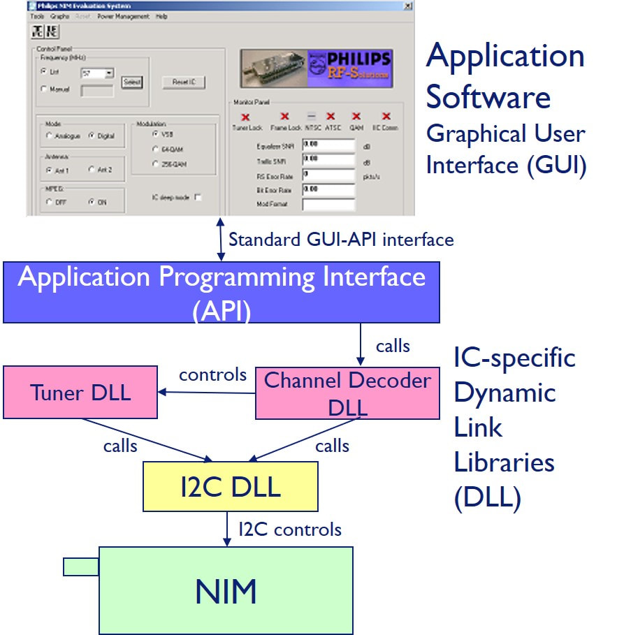
Because the programming features of especially the IF and channel demodulator ICs kept growing, an extensive set of application software was available to customers.
|
Even before joining Semiconductors - or more likely because of joining - the BL went through a round of cost saving restructuring by the end of 2006, reducing some 40 people from a total of 235 indirects. Eindhoven was hit hardest, with most of the former Krefeld tuner developers having to leave. After the restructuring Eindhoven had 25 people R&D left, now only covering Multi-Radio Modules and the IEEE 802.11n Wifi transceivers. Singapore still had its 40 people R&D and covered all can products plus the portable modules. The BL continued desperately looking for profitable new products, indicated by the fact that across the BL 9 engineers were doing system innovation (5 Singapore, 4 Eindhoven) plus another 6 RF innovation in Singapore. The BL now also had 11 software engineers, to cope with the increasing software content of the NIMs as well as the evaluation kits. In contrast only 16 of the 65 engineers were actual product designers: 5 RF and 6 IF in Singapore, 5 MRM in Eindhoven with an equal numer (16) for all design support (lay-out, environmental testing, documentation, component management).
|
At this point it is also interesting to have a short look at the industrial set-up of the BL RF Solutions. As mentioned earlier, all efforts to sell the RFS operations had failed, and it was still entirely under RFS control. Early 2006 the only RFS production site was Batam, Singapore production had been entirely transferred there in the previous years. Outsourcing in Europe to the Kwidzyn fab had stopped after that activity was sold to Jabil by Philips, and the industrial policy was now as follows:
- Batam P1 (SMD onsertion and reflow soldering) was always kept fully loaded. It operated 8 P1 SMD-onsertion lines, 7 FCM and one AX3 for the advanced portable radio products like the Nokia TV-on-Mobile module. In 2006 4,5 of these lines were for the still highly successful MultiMedia products, 1,5 for NIMs and one for STB (cable and terrestrial).
- Because volumes were rising dramatically, especially of the digital off-air TD1300, the majority of P1 was outsourced to local Electronic Manufacturing Services (EMS) suppliers next door in Batam, a total of 11 FCM-equivalent lines in 2006!
- The same approach was followed for P2 (hand insertion) and P3 (alignment and testing): 6 lines were kept in Batam, for new products, ramp-ups, and reference production to guarantee good quality across all sub-contracters. By 2006 these 6 lines were exclusively used for STB products.
- All other P2 and P3 for Multimedia and STB was sub-contracted to local EMS suppliers in Batam: 6 lines for MultiMedia, 2,5 for NIMs.
- Suzhou (Jiangsu Province, immediately NW of Shanghai) was the second largest production site, and the only one apart from Batam that had full P1-P2-P3 capability. In Suzhou the operations were under the Philips China (PCA) and Victory alliance. It operated four full lines that produced all standard and feature tuners for the BL, some 8,5Mio modules in total. It was planned to start moving STB products to Suzhou in 2007.
- For advanced products, mainly the small-size portable radio products that contained 0201 SMD components, sub-contracting to specialised EMS suppliers was foreseen, mainly in Thailand.
TV-on-Mobile, 2005-2009
|
The primary reason for the positive support for RF Solutions migrating to Semiconductors was its involvement in TV-on-Mobile. In this application broadcast TV is received by a mobile phone or other handheld device, for content watching on a small display. In the previous decades there had always been (very) small screen (almost) portable TVs, but these were based on reception of the standard analogue TV broadcast signals. TV-on-Mobile was the logical next step after earlier satellite, cable and terrestrial digital TV. And similar to those segments, also for TV-on-Mobile multiple standards emerged. The leader, ahead of all others, was Korea, which in 2005 launched its Digital MultiMedia Broadcast (DMB) service, both via satellite (S-DMB) and terrestrial (T-DMB). T-DMB would become one of the main contenders for global standardization. In the US the ATSC defined ATSC-M (Mobile), while in Europe the Digital Video Broadcast groep defined DVB-H (Handheld). Whereas DVB-T transmits multiple channels continuously, which are multiplexed using OFDM, DVB-H transmits each channel in time-multiplexed short bursts, so-called slices. This way the receiver only needs to be switched on, in a synchronized way, during the bursts of the selected slice. Depending upon the number of multiplexed channels the receiver is therefore only active 10-15% of the time. In the US the company Crown Castle obtained an FCC licence for transmitting DVB-H in the L-band between 1455 and 1495MHz, strengthening the DVB-H case. Japan, finally, developed the Integrated Service Digital Broadcast ISDB-T standard for mobile TV reception. In Europe, one of the biggest promotors of the new DVB-H standard was the then leading mobile phone player Nokia, who developed an aggressive plan for launching DVB-H enabled phones.
|
TV-on-Mobile
|
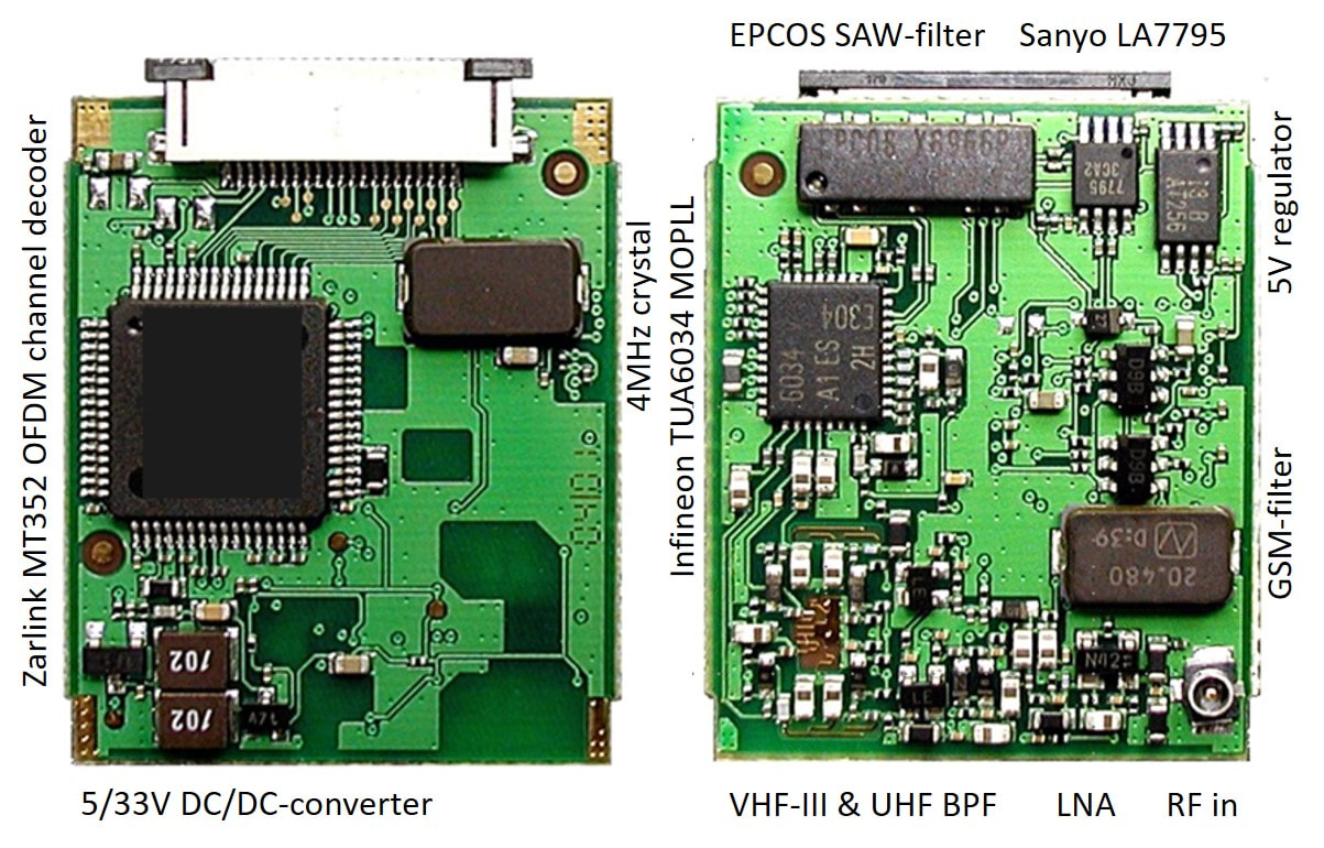
The Philips PDD2016A DVB-T NIM. It measured only 25 by 31mm at a thickness of 5mm. The different key components are labelled around the periphery.
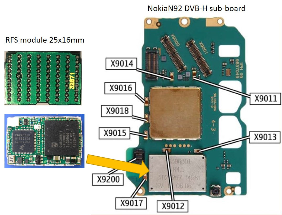
The RF Solutions DVB-H module (left, bottom and top view) and mounted inside a Nokia N92. The markings say R4.5 (the Nokia Release), 3112 297 14581 (the 12nc) SV10 (meaning Singapore/Batam pre-production status) 0606 (production June 2006). [Module picture Thomas Fenkes]
|
To this end they issued a Request for Quotation (RfQ) to which Philips responded with a proposal based on a Semiconductors chips set. But when Nokia demanded a full module solution, and given the recent decision by Mario Rivas to integrate RF Solutions, this BL is added to the project to provide a module solution. March 2005 was the final presentation to Nokia. As reference of its competencies the BL RFS showed the PDD2016A DVB-T NIM which was just released and measured 25 by 31mm. Nokia was impressed, and Philips was selected for what was called the Release 4.5 (R4.5) very first product, with a very tight planning. The module was based on an architecture defined by Nokia, using a Freescale Zero-IF tuner IC (36mm2 large!) and the 11x11mm Esteri OM6395 ASIC developed by the BU Mobile on specifications of Nokia. The module, which never received an official BL name, was released by the end of the year and used in the very first Nokia DVB-H mobile phone, the N92 smart phone that was launched November 2005. At the time this was a major publicity success, being the key module supplier in the first mobile-TV product of the number one mobile phone maker!
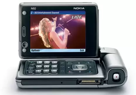
The Nokia N92 smart phone, the first in the world to feature DVB-H TV-on-Mobile reception.
|
In parallel RF Solutions released a last DVB-T only module as successor of the PCD2016, the PDD3016. It used the latest Philips Semiconductors TDA10048 channel decoder, and the new TUA6041 "Lightning" Infineon MOPLL for automatic alignment. This IC integrated three D-to-A converters (DAC) to provide the external varicap tuning voltage based on tuning tables stored in a small EEPROM connected to the channel decoder. However, this architecture was eventually used only once in this PDD3016, because portable TV solutions not including any of the new TV-on-Mobile standards were no longer state of the art. From here on, all RF Solutions TVoM products targeted DVB-H, with the occasional DVB-H/T dual-mode versions.
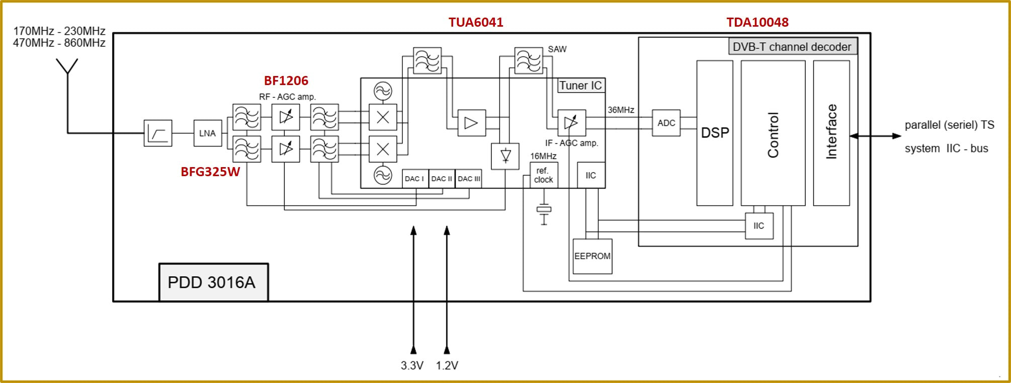
Block diagram of the Philips PDD3016A, the last DVB-T-only portable TV module of RF Solutions. Note the three DACs on the TUA6041, that control the tuning voltages of the input matching and bandpass RF filters. Tuning data is stored in the I2C-controlled EEPROM. [PDD3016A Data Sheet, 27-11-2006]
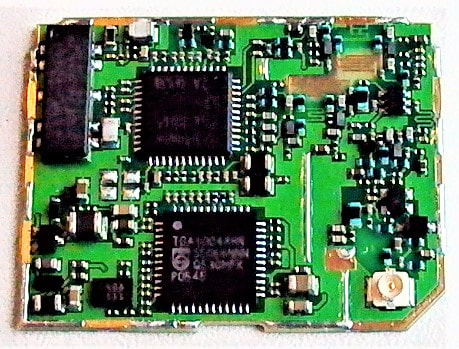
The Philips PDD3016, the last DVB-T-only module by RF Solutions. On top the Infineon MOPLL, below it the TDA10048 channel decoder with lower left next to that IC the small EEPROM for the tuning data. [Thomas Fenkes]
|
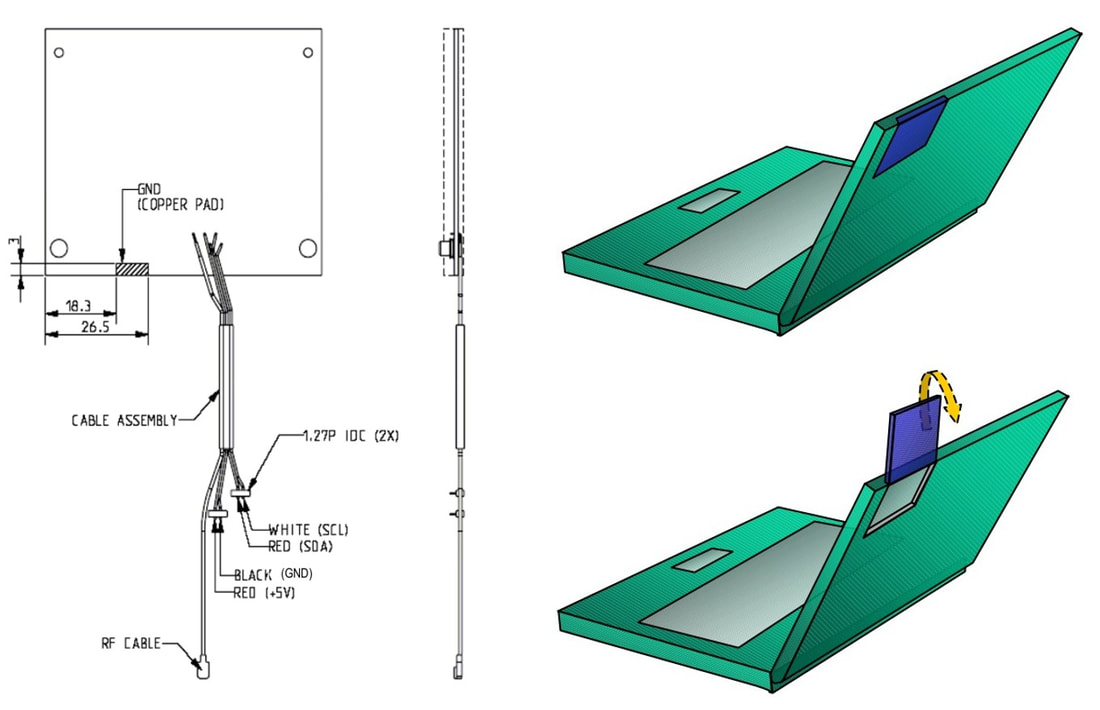
With the PDD3016 came the ANT2216W active antenna. It was developed in Singapore, and contained switched (I2C-control) diversity antennas and LNAs (in which case the LNA on the PDD3016 was deleted). On the right a suggested laptop application. [PDD3016(A) Application Note, 28-8-2006 via Detlef Marbach]
|
Where the first Nokia product was based on a large amount of opportunism to achieve the fast time-to-market, based on the Nokia design-in success a more structured product roadmap was developed, now using Philips components. The first was the TDA18281 DigiMob1 ZIF tuner. This was not an IC specifically architected for DVB-H, but, driven by time-to-market and the necessity to replace the Freescale tuner, a modification of the only ZIF IC available within the company: a 3G UMTS transciever IC. Due to the lack of an input AGC it was marginal on non-linear performance but substantially smaller - and thus cheaper - than its Freescale competitor: 2,2 instead of 36mm2! On the channel decoder side there were two options: a modified DVB-T IC from Rennes, the TDA10101, which was hard-coded and thus very power efficient and small, but not flexible. The latter was deemed a major risk, given the continuously changing Nokia requirements. The alternative was a DSP-based platform, designed in Dresden for WiFi, the TDA10105 Colorado IC which could handle both DVB-H and DVB-T. For the next generation DVB-H for Nokia (Release 6) Philips therefofe offered three options, which were all brought to prototype status by RFS:
- BGT200 System-in-Package (SiP) containing the tuner, TDA10101 channel decoder and a PMU. To save area the tuner IC was mounted on top of a PICS passive integration IC from Caen, so the module contained four Si dies. It measured 9 by 9mm.
- BGT205 module, containing the BGT200 SiP plus the GSM filter and diplexer components. It measured 13 by 10mm and had a metal cover similar to the R4.5 module.
- BGT210 pin-compatible with the R4.5 module. This was a classical RFS module, with packaged ICs mounted on a multi-layer PCB. In contrast to the BGT200/205 it used the Colorado TDA10105. Dimensions were 25 x 16mm.
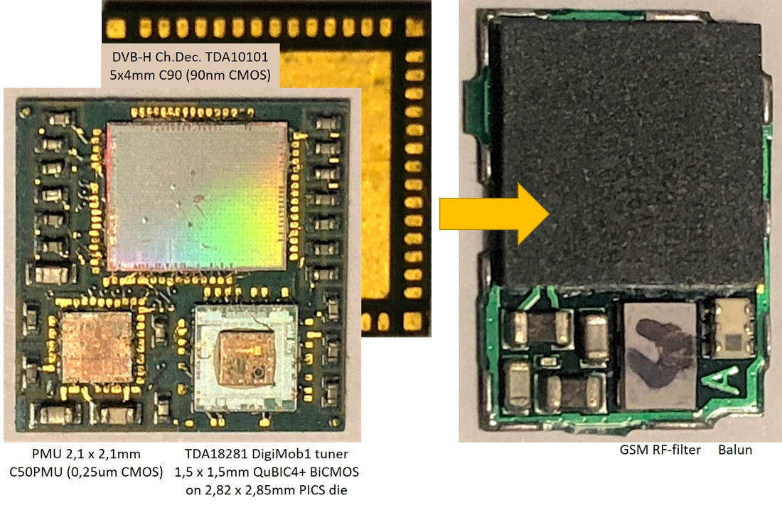
The BGT200 SiP (left) and BGT205 module (right). The SiP used a standard Laminate Platform (LAMP) FR4 base of 9 x 9mm with wire-bonded chips. The BGT200 was flipped and reflow soldered inside the BGT205. [Detlef Marbach collection]
|
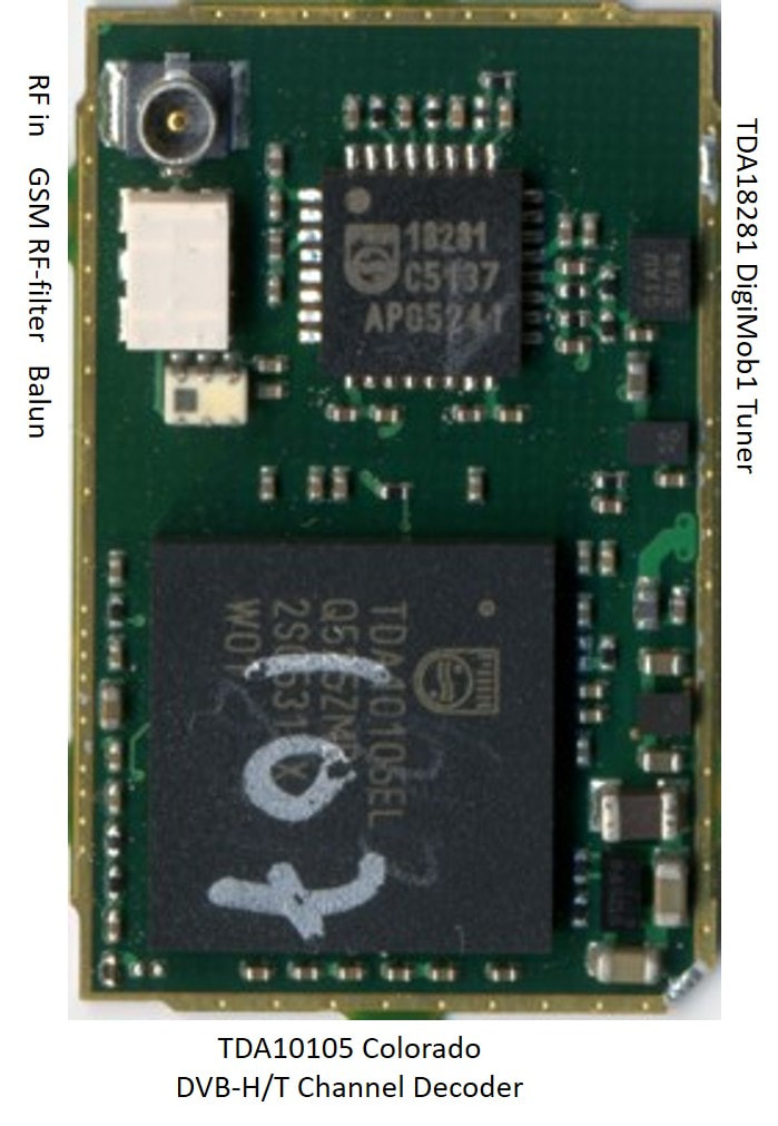
The BGT210, a standard RF Solutions module with packaged ICs mounted on an FR4 PCB.
|
The BGT200-205-210 differences summarize one of the main strategic issues that RF Solutions had been struggling with for more than ten years already: the standard RFS technology of packaged ICs mounted on FR4 PCB inside a metal can was becoming outdated for the type of functions that were now developed. Although the BGT200 SiP clearly did not contain the full RF function (the GSM filter and balun were too big), the unpackaged silicon dies allowed much smaller footprints. But handling naked dies and wirebonding were technologies only available in the Semiconductor back end fabs (more specifically the PSPI fab in Calamba in the Philippines) and not in the Batam RF Solutions fab. Using the PSPI production flow, however, gave a completely different cost and margin model for RFS. Also the product coding reflected that the TVoM products were more Semiconductor-like than RFS-like; similar SiP modules were named BGB200 for Bluetooth and BGW200 for Wifi. It remained a struggle.
|
After missing the R6 slot, Philips (now NXP) continued developments to win back Nokia. To that end the BGT215 was developed as an even smaller SiP: 7 by 7 mm, which was achieved by stacking the three dies on top of each other: the TDA10105, a PICS passive integration die and the TDA18281 (the PMU IC was moved to the outside of the module). Although publicly announced in April 2007 there are no traces of actual use. It was, however, used as SiP-inside-a-module by RF Solutions in the PDD3026, which was a combined DVB-H/T module. In parallel RF Solutions brought out the TV1000 module in the SDIO memory card form factor.
|
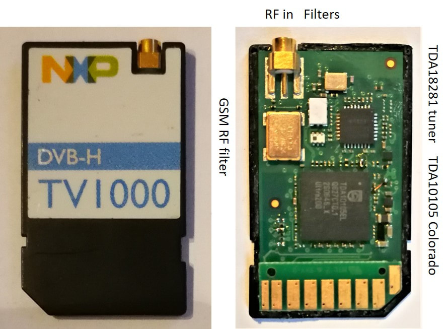
The NXP RF Solutions TV1000 DVB-H SDIO module, using the same architecture and key components as the BGT210. [Jan van Daal collection]
|
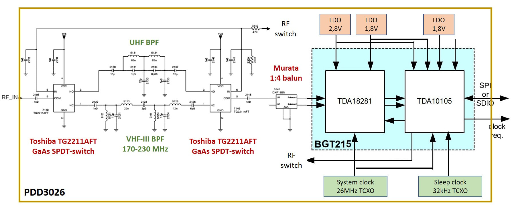
The Philips/NXP PDD3026 combo DVB-H/T module. It contained the BGT215 3-layer SiP, but additionally RF band switches, 2 Temperature Controlled X-tal Oscillators (TCXO) and three Low Drop-Out (LDO) voltage regulators. The BGT215 was a stack of three dies: on top the tuner, then a PICS passive integration die, and below the TDA10105 CMOS IC. [PDD3026 Data Sheet and Circuit Diagram, Thomas Fenkes]
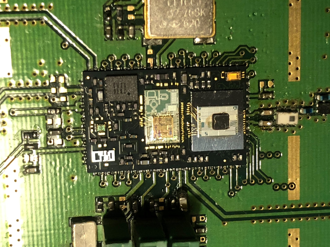
A last TVoM experimental module: a Wifi-TVoM combo module. Basis was the BGW211 Wifi module with the TD10105 Colorado, the TDA18281 DigiMob and its PICS die added on top. This prototype was built jointly with the RF Innovation Centre in Nijmegen. [via Detlef Marbach]
|
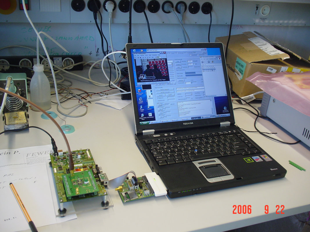
The functions became increasingly complex, also for evaluation. Here we see the Wifi-TVoM combo module on an RF board which is in turn mounted on a system board. This latter board is then connected to the laptop through a PCMCIA digital capture interface card. The laptop shows the application and evaluation software GUI. [via Detlef Marbach]
|
And then it was almost overnight all over. Although by 2006 and 2007 the first countries started DVB-H TV-on-Mobile transmission (Italy, India and the Netherlands were leading) the adoption rate was minimal. Mobile phone users simply did not want to pay for TV on their mobile phone, since the average viewing time was only a few minutes per day. The most important reason, however, was that with the then launching 3G phones, but especially the next generation 4G, video content would simply be watched on-line in streaming mode. In other words, the concepts of Conditional Access paid broadcast TV and the "free" internet access of the smart phone did not match, and the broadcast evidently lost the fight. Interest in TV-on-Mobile, DVB-H and T-DMB collapsed, most experimental broadcast was discontionued in 2008, and of course all product development stopped. For RF Solutions it had been a fruitful exercise, enforcing the adoption of much finer integration technologies, while it had also been the key to being allowed into Semiconductors/NXP. But as a business segment it had been disappointing: despite the many products developed, only a few Mio€ sales was achieved by 2007, most of which the low-margin R4.5 Esteri module sales to Nokia.
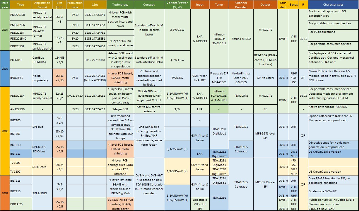
Overview of the many different products developed by Philips/NXP RF Solutions for portable TV DVB-T and DVB-H standards.
TDA18270 3rd Generation Si Tuners, 2006-2010
Although the first two generations Silicon Tuners, the TDA8270 and 8270A, were successful in establishing Philips Semiconductor as a serious contender in this new technology, the customer adoption was still low due to the performance shortcomings. Especially Noise Figure was still high at around 7dB, while the non-linear performance (IP2, IP3) and especially image rejection were not on par with standard can tuners. Furthermore, the die size of 11 mm2 made it a large die, not so much compared to competition which was often even larger, but for internal cost modelling and to make it compete with the MOPLL. The Mk3 SiTuner generation therefore saw some major re-design steps, the first of which was the migration from QuBIC3 to QuBIC4+, which gave a substantial boost in RF performance with a new doubble-poly transistor, but especially a migration to 0,25um CMOS, allowing much denser digital control circuitry. Also functionally quite some optimizations were implemented:
|
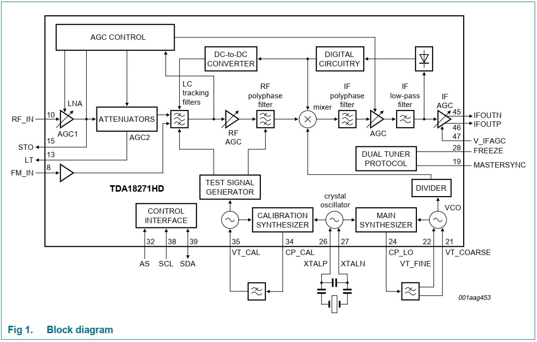
Block diagram of the NXP TDA18271 integrated tuner. [NXP TDA18271HD Silicon tuner IC data sheet Rev.4, 19-5-2009]
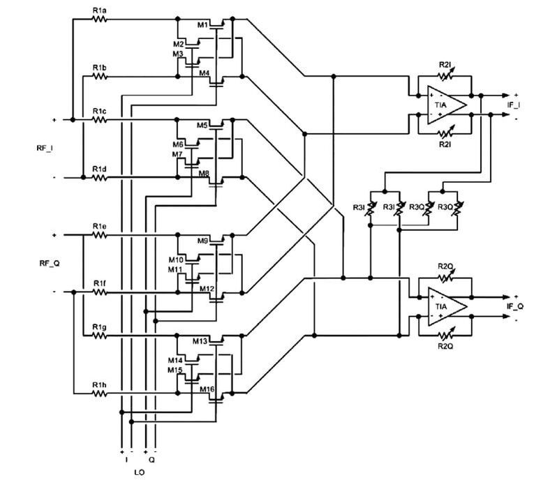
The double-balanced MOS-mixer of the TDA18271. The balanced input signals are generated by the RF PPF, the four adjustable resistors R30 are controlled for optimal I-Q amplitude and phase balance. [IEEE J-SSC Vol.42, No. 12, December 2007]
|
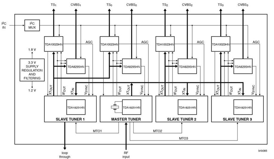
The TDA18251 cable tuner was specifically designed for use in multi-tuner systems, with one tuner serving as Master providing the RF slave output and shared crystal output. The channel ICs were the TDA10023 QAM decoder and the TDA8295 digital analogue TV demodulator. [OM5785C Reference design in NXP silicon tuner TDA18251HN leaflet, 2007]
|
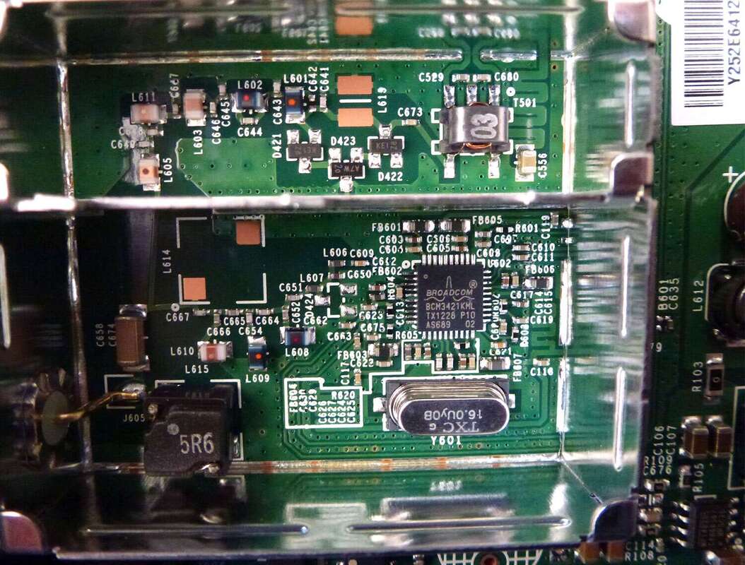
The NXP TDA18251 disguised as Broadcom BCM3421 inside a home-brew tuner can used inside a Motorola Surfboard DOCSIS2.0 cable modem. [EDN Teardown, September 2017]
|
However, the main innovation in the third generation silicon tuner was integrated selectivity, just like a standard tuner! The BL TV Frontends management was obsessed with seeing its silicon tuners replace can tuners also in the TV and STB domain, similar to what had happened for satellite. But as explained multiple times, satellite is a substantially easier RF application than off-air TV, and without pre-mixer RF selectivity no good performance is achievable. As dual-conversion supporters had found out so often. The dream was to grab the margin still taken by the can makers and thus get substantially higher prices for the tuner IC. This BL mentality poisoned the relation with RF Solutions, even after they had joined the same BU Home, since they were seen as competition, not as a valued customer. So, instead of working together with their RFS colleagues in developing an optimal application for off-air reception using the TDA18271, Caen essentially did the tuner design themselves by integrating the selectivity inside the IC package. Because this required coils and varicaps there was only one option short of a tuner: a System-in-Package (SiP) similar to those used for TV-on-Mobile.
|
The concept of the BPF used inside the SiP was not fundamentally different from those used in standard tuners, although simpler and using fewer components due to space constraints. The TV RF band from 45 to 865MHz was split into four sub-bands, each requiring three bond pads on the tuner IC. Most bands used dual varicaps in the latest SOD882 SMD package, the same as used in tuners. These required a 25-33V tuning voltage, which was generated by a separate on-board DC/DC- converter. Because the response of each BPF peaked at the high end of the sub-band, a digitally controlled capacitive divider reduced the input voltage to the RF AGC2 stage. The inductors were all (expensive!) SMD components with a lower Q than typical air coils. Because the coils could not be aligned, an extensive BPF calibration procedure was required.
The SiP used a 9 by 9mm 4-layer laminate substrate and regular 0402 and 0201 SMD components. It was produced, like all Philips/NXP SiPs, in the PSPI Calamba back-end fab in the Philippines until that fab was sold to ST Microelectronics as part of the Mobile JV, and production was transferred to nearby Cabuyao fab. The main runners using this new technology were the TDA18271 full hybrid cable/off-air silicon tuner, and the TDA18211 which was a digital-only off-air drop-out without the VHF-I sub-band. These were the first ICs to benefit from the QuBIC4+DG Dual Gate oxide version, offering a 5,5V transistor for much more efficient I/O-design. This remained the standard technology for all subsequent silicon tuners. It allowed a die size reduction to only 5,2mm2, while the better bipolar transistor drove the integral power consumption town to only 780mW. In performance NXP had taken back the undisputed lead in integrated tuners. However, price remained an issue since the SiP was not cheap, with a price - depending upon volume - around 1,5USD. Also, most customers in the STB and TV world did not dare to drop the protective tuner can. At this point a silicon tuner in a can was not cheaper and better than a classical can tuner! And also the application did not become simpler, on the contrary. The data sheet of a silicon tuner exploded to a 70-page booklet, with endless calibration procedures, to start with the RF BPF and the mixer. But almost every circuit block in the IC was in some way programmable, and the original 5-byte I2C programming sequence of the TUN2000 grew to a 23-byte structure! |
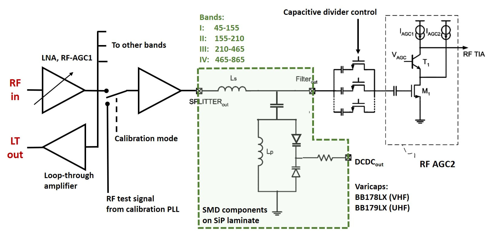
The RF selectivity as implemented in the NXP TDA18211 and TDA18271 silicon tuners. The circuits for one band are shown, there were four (18271) or three (18211) bands in parallel. All components were implemented as SMDs on a laminate SiP substrate. [based on IEEEE article]
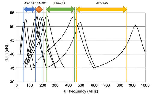
The four sub-band BPF tuning curves of the TDA18271 silicon tuner. [IEEE article]
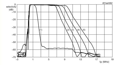
One of the features of the TDA18271 was that it could receive FM radio, for which it had a separate input. Shown are not only the regular 6/7/8/9MHz TV IF PPF curves, but also the 1,5MHz IF-filter for FM. [NXP TDA18271 Data Sheet]
|
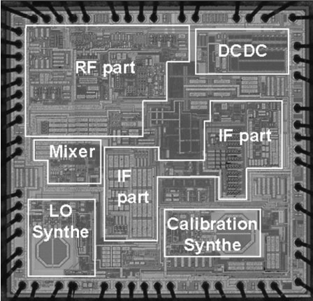
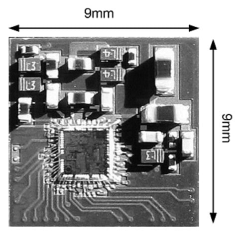
The main question now was of course "is the TDA18271 really fit for its off-air TV application?". Since the BL RF Solutions had solemnly sweared, when joining Semiconductors early 2006, to co-operate with their BL TV Frontend colleagues on promoting and using SiTuners, a thorough evaluation was done by Singapore Development. Basis was the OM5782 evaluation board received from Caen/Hamburg, containing the TDA18271 SiTuner, TDA8295 analogue TV demodulator (PAL, SECAM, NTSC) and TDA10048 channel decoder (OFDM). As reference an FMD1216ME with TDA9887 AFRIC and external TDA10046 OFDM demodulator were used. Although the SiTuner complied with typical requirements on many parameters, there were a number of serious shortcomings:
- integral RF Noise Figure was much higher than the 5dB of the FMD1216, especially at the upper end of the UHF band where some 15dB sensitivity was missing. Loss of synchonisation was also 12dB earlier than for the FMD (at 33dBuV vs. 21dBuV).
- the minimally required analogue input signal was therefore much higher, at least 60dBuV for PAL, 70dBuV for NTSC, as opposed to the typical 50dBuV for a can front end.
- because of the Zero-IF (ZIF) architecture without SAW filters, group delay was less optimal, resulting in ringing in the video signal. Epecially for LCD displays this was an issue.
- due to a lack of selectivity, especially at the upper end of the UHF band, sensitivity for digital reception degraded by up to 15dB.
- for the same reason N-1 adjacent PAL interference rejection was up to 20dB worse.
|
With this third generation at least the performance for cable applications was meeting all requirements, and TDA1825x cable silicon tuners were thus the main runners of the family. One of the cable-specific extensions was the frequency range of 1002MHz, a topic discussed for at least ten years before, especially in the US. However, even despite it now being offered, not many cable networks were in the end upgraded to 1GHz. Another interesting cable version was the TDA18260 dual tuner, which started to make sense since a typical cable box contained 4 or 8 tuners. Dual tuners were also an old BU Tuners topic, which had always been on the wish list, but was invariably blocked due to RF interference and beats. On the TDA18260 this was solved by using two different PLLs: a first one with an LO at 7,17-8,07GHz and a 8/15 divider, the second LO at 6,17-7,06GHz and a 7/13 divider. Other than that it were two identical tuners with a common input and loop-through. The dual tuner worked in combination with the TDA10023 dual QAM channel decoder.
|
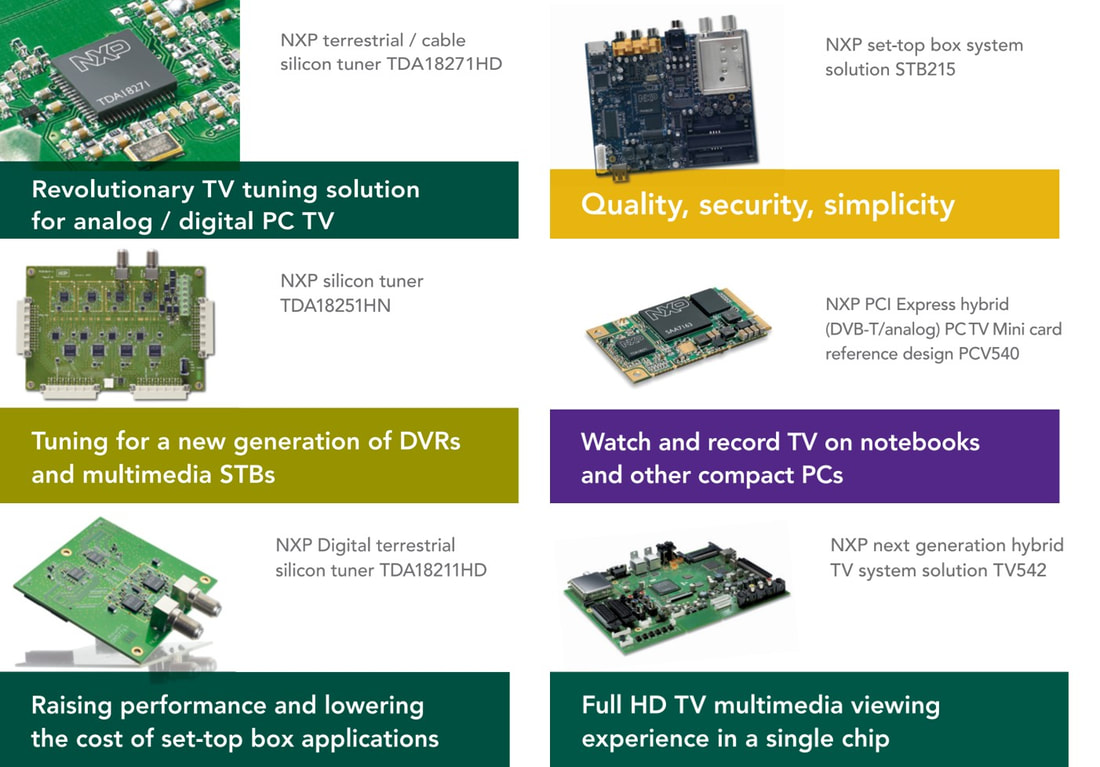
The NXP TDA18271 Hybrid silicon tuner and its family members or derivatives were broadly advertised for the different PCTV, STB and TV applications. [NXP Reference design leaflets, 2008-2010]
|
At this time, around 2009, the next challenges the (silicon) tuner had to deal with were new and more demanding standards. The DVB-C, DOCSIS, DVB-T and ATSC standards, to name the most used ones, were around ten years old, and technology had made steady progress in those years. So most of them underwent some sort of upgrading:
- DOCSIS/EURODOCSIS3.0 (they were now harmonized) introduced, still based on DVB-C, channel bundling, maximum 32 downstream and 8 upstream. This allowed bundled data rates of 1,4 and 1,8Gb/s in the US and Europe, respectively. IPv.6 became the standard for internet data transfer. It was released 2006.
- DVB-C was succeeded by DVB-C2. It took over the OFDM basis of DVB-T, using QAM for the sub-carriers. Cable conditions allowed to use the incredible concept of 4096QAM per carrier, resulting in a 12 by 12 constellation diagram! This resulted in maximum 83Mb/s in a standard 8MHz channel. DVB-C2 was released in 2008.
- DVB-T was succeeded by DVB-T2. Still based on OFDM but with most parameters upgraded: multiple transport streams, advanced coding schemes, 256QAM per carrier with reduced guard intervals, 32k FFT and H.264 instead of MPEG2 video coding. All this still within the standard 7 or 8MHz band, which meant that especially phase noise requirements increased due to the higher modulation scheme. The specification was formalized by ETSI in 2009 and in 2010 the UK was one of the first countries to start transmitting, followed step-by-step by most DVB countries.
- ATSC was first upgraded to ATSC2.0 under standard A/72, mainly covering a switch to H.264 too. Shortly after it issued a demanding upgrade specification, A/74, requiring 56dB N+/-1 adjacent analog channel suppression.
|
The last tuners of the third generation therefore introduced performance improvements linked to these new standards:
|
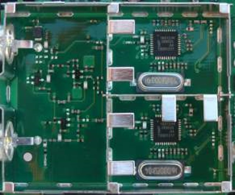
Two NXP TDA18212 DVB-T2 off-air tuners in a Sagem STB module.
|
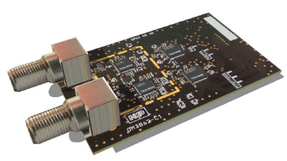
A typical reference design, here the TDA18212 multi-standard digital off-air tuner with the TDA10048 channel decoder. The yellow dotted line is the solder ring for the metal cover. [NXP OM3862 Reference Design, 2010]
|
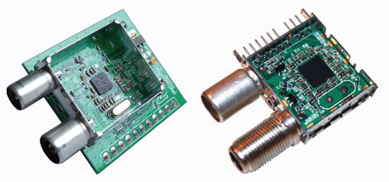
In the end the BL TVFE was forced to deliver complete tuner reference designs, 100% identical to what RF Solutions would deliver, including connectors, frame and pin block. Here examples of the TDA18250 cable tuner for China. [NXP OM3914 Reference design]
|
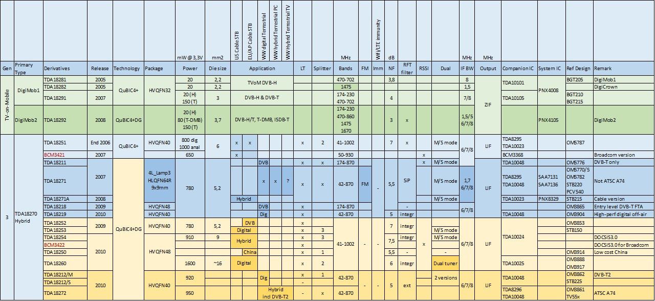
Overview of the NXP TDA18271 and TDA18272 third generation Hybrid Silicon Tuner families as well as the DigiMob tuners for TV-on-Mobile.
UV1300-Mk5 and HD1800, 2007-2008
After the big success of the Philips Jaguar TV platform and its UV1318-Mk3 high-performance tuners, the co-operation between Brugge TV and Singapore RFS continued for the next generation. On the TV side these were two major flagship platforms: the TV520, based on the first NXP PNX8541 SoC and the LC8 for standard LCD. The Q522 chassis, first of the TV520 platform, was targeted to ramp mid 2007, while the next Q521, Q529 and the LC8 ramped up in 2008. Compared to the UV1318-Mk3 - and to a lesser extent the low cost UV1300-Mk4 - the new requirements were limited:
RF solutions translated these requirements into a very limited family, the UV1300-MK5:
|
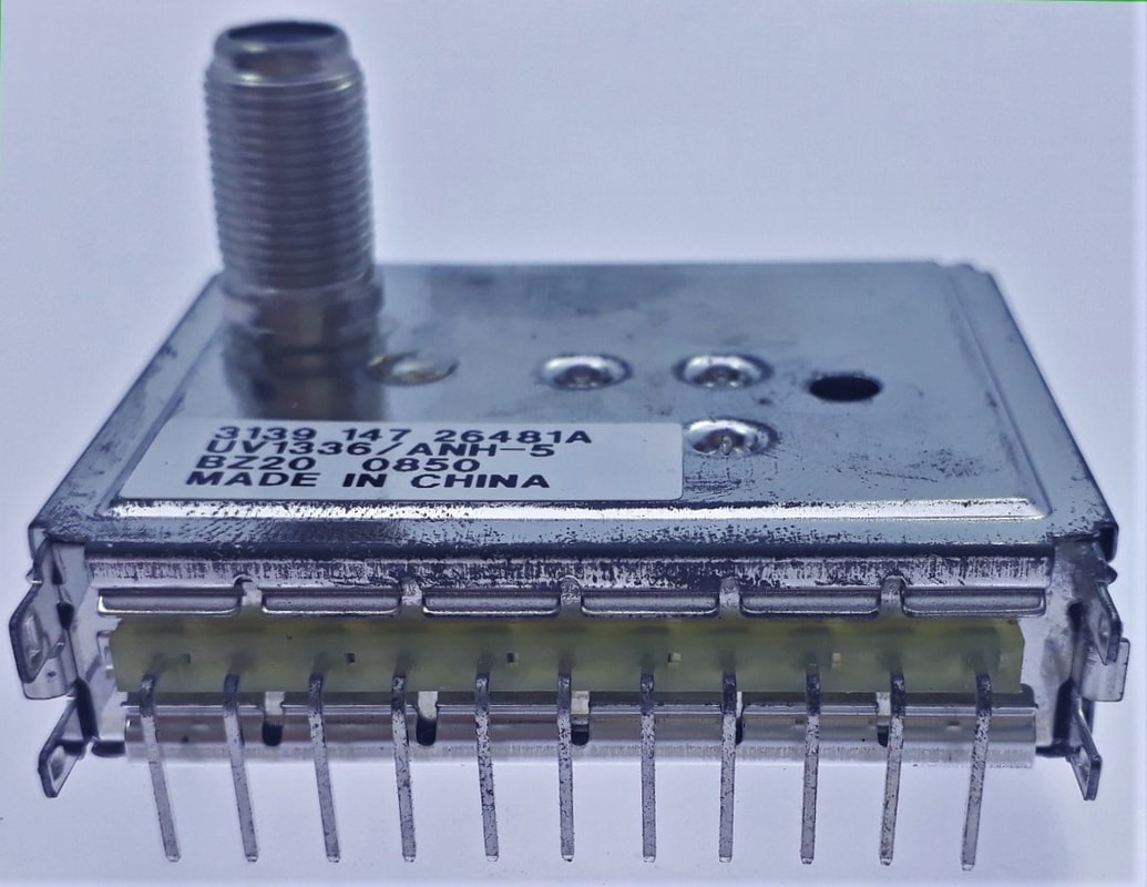
Nice picture of the NXP UV1336/ANH-5 NTSC tuner with new vertical connector (suffix N). All Mk5 tuners were produced in Suzhou, as indicated by the manufacturing code BZ20.
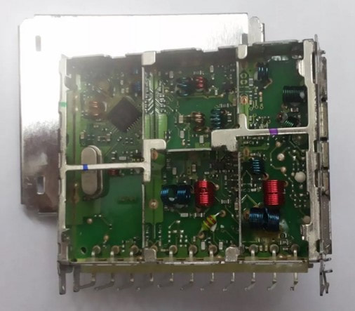
The only available interior picture of a UV1300-Mk5. Upper left the TDA6509 MOPLL, 45degrees rotated for optimal soldering.
|
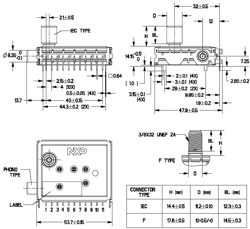
Mechanical outline of the NXP UV1300-Mk5 with the vertical connector. [UV1316E Data Sheet via Lim Kui Yong]
|
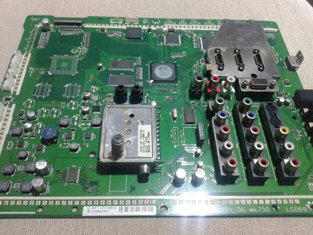
A rare UV1336L/ANH-5 with RF loop-through and phono output connector on the 52PFL7808 large screen LC8 chassis for South America.
|
Although designed to be compatible with the TD1700-Mk4, in practice there was a rather hard split between the two tuner families. The Q520 hybrid chassis used the TD1700 digital tuners, while the L8 utilised the UV1300-Mk5 analogue tuners. In case an L8 chassis should support digital reception a loop-through UV1300L-Mk5 was used, with a TD1700 on a digital add-on board. Chassis for China were the exception, since no digital functionality was required (that was all covered through set top boxes). For the Q522 an analogue UV1318S tuner that was pin-compatible with the TD1700 was made: the UV1718S. It is a rarely seen tuner. For the Q529 and Q540 family it is even worse: the analogue China version was called UV1783S-MK5, an analogue only derivative of the TD1700-Mk4 but without the LNA. Although it is mentioned in all TV Q529 and Q540 data sheets, no practical traces have been found so far. It may well be - this happened more often - that the tuner type indication in the TV data sheet of a still to be released tuner was not accurate, and that the real tuner that these data sheets referred to was the UV1856-Mk5, which was the very last Philips/NXP analogue tuner. It was used in the 2009 LC9 chassis, which probably was a TPV developed chassis but still - as the very last - using an NXP tuner.
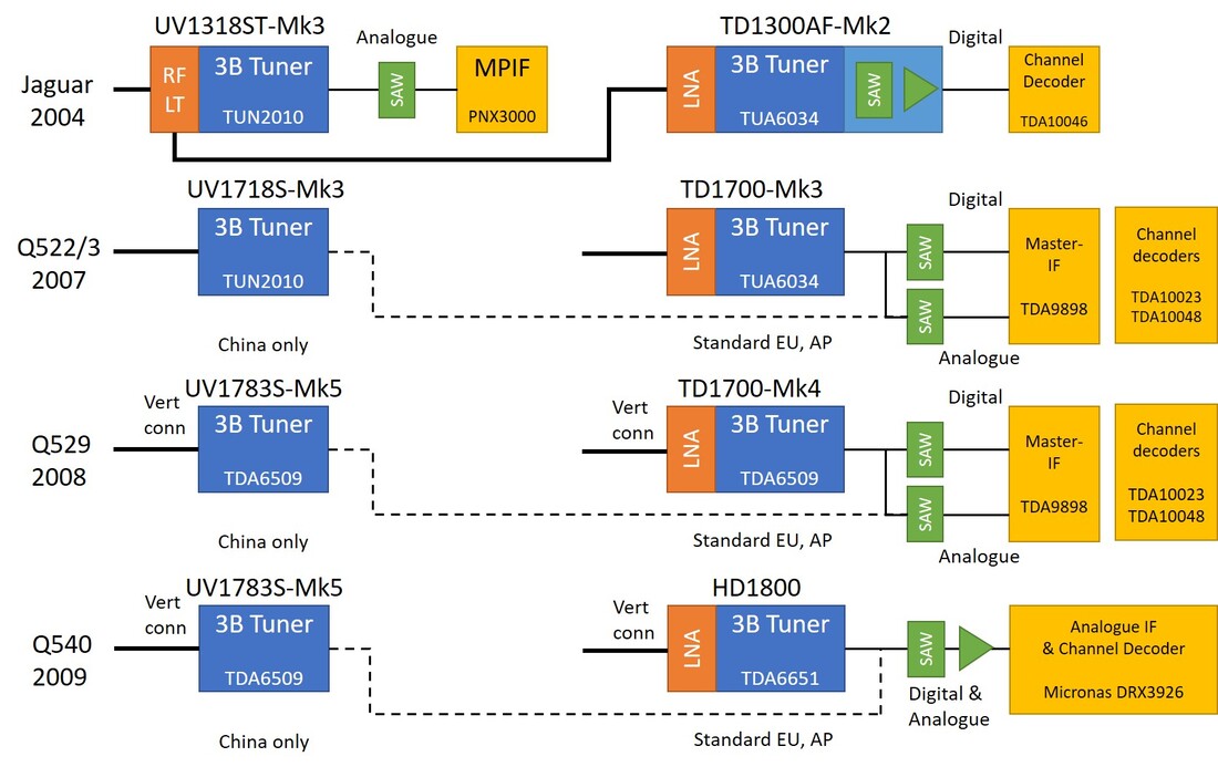
The Jaguar platform (2004-2006) was the last where the analogue tuner was prime, and the digital tuner an optional slave. From 2007, with the Q522 and Q523 chassis, the analogue switch-off started and the hybrid tuner became the single tuner module, only replaced by a classical analogue tuner when digital reception was absolutely not required. The diagram shows that the IF and channel decoder integration also determined the tuner module functionality.
|
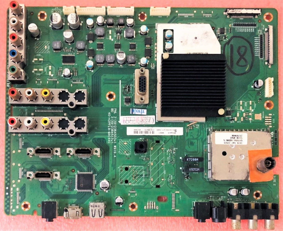
The last purely analogue Philis/NXP tuner, the UV1856/ABHN-5. 56 indicates it is a PAL-D/K tuner for China, A= asymmetrical IF output (unfiltered), B= vertical IEC conncetor, H= horizontal mounting, N= N-1 trap in the IF. The mother board belongs to an LC9 chassis using a MediaTek core processor under the heatsink.
|
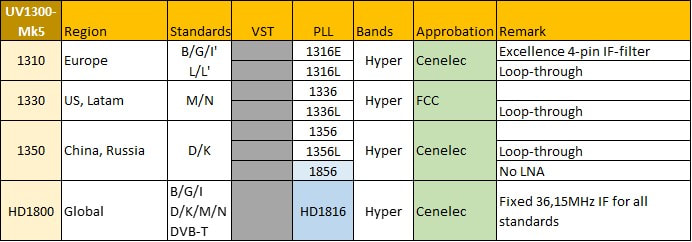
Overview of the very last Philips/NXP TV tuner family, the UV1300-Mk5 and single HD1816.
The very last tuner that can be classified as analogue became the HD1800, although the type naming (Hybrid Digital) already indicates it is a hybrid analogue-digital module. However, because the data sheet explicitly lists all analogue standards the tuner still covers I give it the label of "last analogue tuner". At the same time it did away with the classical analogue standards, because the IF frequencies were all shifted upwards to make them more centered around the 36,15MHz digital TV SAW filter. For PAL B/G, D/K, I and SECAM-L the picture carrier IF now was 39,9 instead of 38,9MHz, while the lowest sound carrier was 33,4MHz (for SECAM L). A single 8MHz SAW centered at 36,5MHz now covered all frequencies between 32,5 and 40,5MHz. Even the NTSC M/N standards were covered with the unusual 38,0MHz for the NTSC picture carrier. The demodulation of all these non-standard IFs was executed in the digital domain by a new Micronas digital demodulator and channel decoder, integrating the Master-IF and separate channel decoder functions. As a consequence of this concept for the first time all global standards could be covered by the same tuner, and consequently there was only one version: the HD1816.
Although the HD1800 had a different name, in essence it was still a classical 50mm World Standard Pinning (WSP) analogue tuner, almost compatible to the first generation UV1300 introduced in 1994. Developments that will be described in the following sections, technically but especially politically and organizationally, in the end made this the last WSP tuner family, the last Philips/NXP analogue tuner family, and the last time a Philips/NXP tuner was used on a Philips-developed TV chassis. A memorable milestone.
Although the HD1800 had a different name, in essence it was still a classical 50mm World Standard Pinning (WSP) analogue tuner, almost compatible to the first generation UV1300 introduced in 1994. Developments that will be described in the following sections, technically but especially politically and organizationally, in the end made this the last WSP tuner family, the last Philips/NXP analogue tuner family, and the last time a Philips/NXP tuner was used on a Philips-developed TV chassis. A memorable milestone.
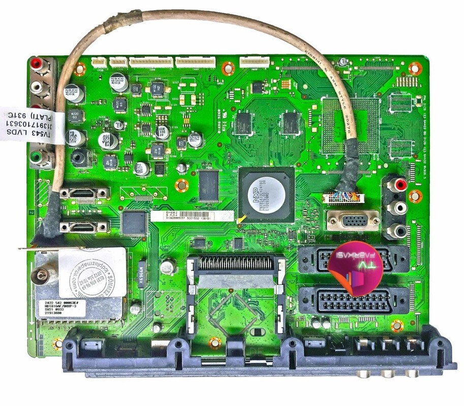
The last Philips TV chassis with RF Solutions tuners on board: the TV540. This is the 42PFL5404 Q543 chassis from 2009 with the HD1816AF/BHXP tuner. A= LNA wideband input amplifier, F= 50mm WSP, B= vertical IEC connector, H= horizontal mounting, X= no digital IF SAW and AGC amplifier, P= RF power on pin1.
|
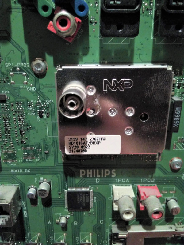
Close-up of the NXP HD1816AF/BHXP hybrid tuner on the Q543 37PFL9604 high-end chassis. Note the single W9969X SAW filter on the right of the tuner, covering all standards.
|

Overview of the last two generations of analogue-centric WSP tuners from NXP, the UV1300-Mk5 and HD1800. The UV1783S, although consistently mentioned in the TV data sheets, remains an enigma, but is included for completeness.
RF Solutions becomes Nutune, 2007-2010
The BL RF Solutions, after much discussions, had barely landed within Philips Semiconductors early 2006, when everything changed as NXP was created. Early 2007 KKR and its allies were all over the BUs and BLs to look in detail to the different businesses, and quickly concluded that they did not want module businesses. (Note by the way that NXP management in these discussions was rather irrelevant). This not only related to the RFS modules, but also to the Nijmegen mobile phone Power Amplifiers, which were completely discontinued. The main reason was that the (RFS) modules, when compared to the typical NXP ICs, made lower gross margins (typically 35-40% vs. 55-65% for ICs) and less profit (10% vs. 15-20%). Which is true, apart from the fact that modules make their lower margin on much higher sales prices. It was rightfully, but unfairly, concluded that modules could never reach IC business targets and therefore had to go. Around June 2007 it was announced internally that it was the management intention to sell RF Solutions, and further restructuring was initiated to prepare the buisness for such a move. By October it was announced that all multi-radio developments would be stopped, including the TV-on-Mobile, GPS and Wifi segments. Only ATOP, an automotive GSM-GPS module that had recently started, and Wifi 802.11n were to continue. In Eindhoven some 15 engineers and supporting staff lost their job, and in Singapore roughly the same number. The most surprising element of the announcement, however, was that the BL would re-focus exclusively on TV tuners! This was undoubtedly pushed by the BU Home management, that did not want any mobile or non-TV developments under its wings. So where the BU Tuners and later BL RF Solutions had been trying desperately to create new business segments, away from the declining tuner market, all this - as far as still alive - was now stopped, at least in terms of new developments. The BL was portfolio-wise back to where it had been during the early 1990s.
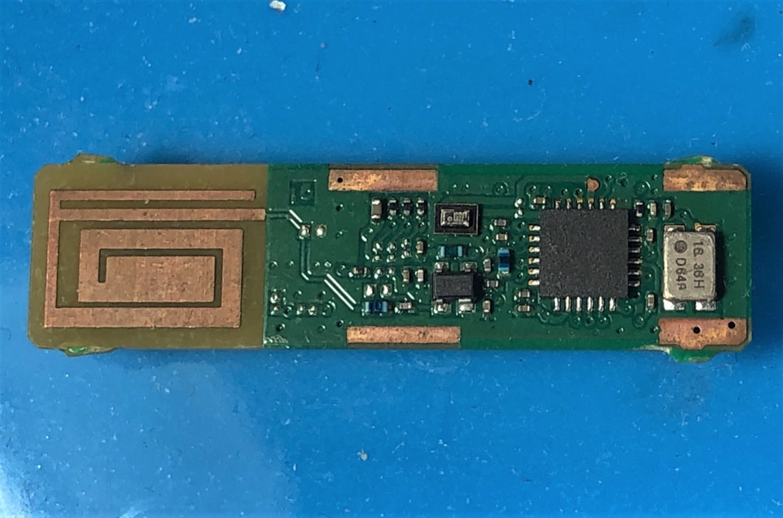
One of the new product categories that did not survive the Nutune creation was GPS modules, the GHA1800 and GHA1801. This is an example with printed antenna for 1,6GHz. The board uses a SiGe4210 IC. [Detlef Marbach collection]
|
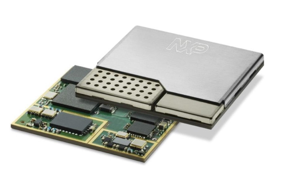
The Automotive Telematics On-board Platform (ATOP) project, a 2,5G Edge mobile transceiver plus GPS, was transferred to the BU Automotive in Nijmegen and Caen, and finally released as the OM12000. It was a very complex module, with multiple internal screens on a BGA. In 2014 NXP sold this business to the Israeli company Telit. [via Thomas Fenkes]
|
Negotiations on the details took almost a year, but then finally in June 2008 a new Joint Venture (JV) was announced:
NXP Semiconductors and Thomson have signed a definitive agreement to combine their can tuner module operations in a joint venture. NXP will have 55 per cent holding in the new venture and Thomson the remaining 45 per cent. In 2007, these operations posted combined sales of over approximately €160m. The new organisation will comprise approxmately 4000 employees, the majority of these being staff from NXP and Thomson manufacturing operations in Indonesia.
NXP Semiconductors and Thomson have signed a definitive agreement to combine their can tuner module operations in a joint venture. NXP will have 55 per cent holding in the new venture and Thomson the remaining 45 per cent. In 2007, these operations posted combined sales of over approximately €160m. The new organisation will comprise approxmately 4000 employees, the majority of these being staff from NXP and Thomson manufacturing operations in Indonesia.
|
Choosing Thomson as the JV partner had some logic in the sense that they were the only remaining European tuner manufacturer. (Remember that Temic had recently been bought by Microtune). But at the same time the Thomson tuner business was much smaller than that of Philips/NXP: at the last known comparison in 2002 it was 28 versus 11Mio units. From that perspective the 55:45 share division was surprising, and probably an indication of the desperation of the new (KKR-directed) NXP management to get rid of the BL RF Solutions at any cost. The deal was formally closed on September 1st, 2008 (almost to a day the same date as the closing of the ST mobile phone JV) and the new company was registered as Nutune Singapore Pte. Ltd. Pieter Paumen, the manager of the BL RF Solutions, became the CEO with a CFO from Thomson. The new company had the following main assets:
For almost a year after the first announcement June 2017 discussions had been ongoing on the structure of the new company, which was mostly along lines of a European and Singapore organisation. However, shortly before the JV was established this was changed into a functional split: all R&D under a former Thomson manager in Villingen and all Marketing and Sales under former RF Solutions management. |
The new Nutune logo.
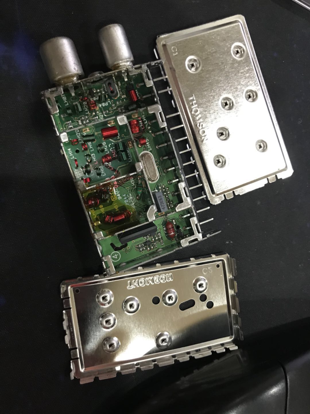
A typical Thomson module from the time of the merger, the DCT7045B digital cable tuner. Although in many aspects similar to RF Solutions products, the main visual differentiator is the use of printed text on the PCB component side.
|
The former Philips and NXP tuner factory at Batam, Indonesia, now marked as Nutune. It produced 2/3rd of all Nutune products. The Thomson fab was immediately to the right of it.
|
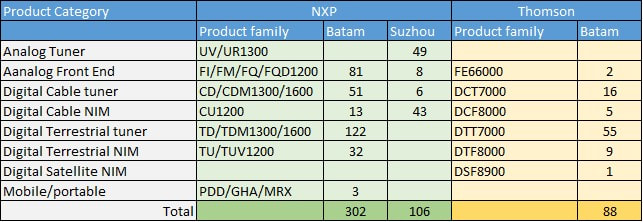
Overview of the product families in production at the start of Nutune, second half of 2008. Clearly the analog UV1300 tuners had been replaced as main product by the digital terrestrial tuner.
|
Nutune inherited a portfolio of some 500 active products, three quarters from NXP RF Solutions , less than 100 from Thomson. However, the portfolios overlapped almost completely, with the majority of the Thomson products being electrically and mechanically compatible to an NXP product. Because Thomson apparently did not use a product coding system compatible to the Philips/NXP 12nc system, a new - so far not de-ciphered - coding system was defined, as well as a new product naming convention. Active products continued to be produced for the existing customers, initially under their old name with the new Nutune code added on the product label. But the main runner TD1600 family was recoded as FT3100 (Front End Terrestrial), as was the CU1200-Mk3 into the NC3270 (NIM Cable). In parallel the NXP FQD1100, CD1100 and TD1100 families, that were already in full development at the time of the merger, were released under their original NXP name, although the TD1100 was later also renamed FT3100. The main runner of Thomson was the DCT707, a digital cable tuner for China where it had a 55% market share. This module was roughly identical to the CD1300-Mk2 (65mm WSP frame) and much larger than the comparable NXP CD1100. Interestingly, Thomson (55%) and NXP (45%) had a virtual monopoly of China cable tuners when combined.
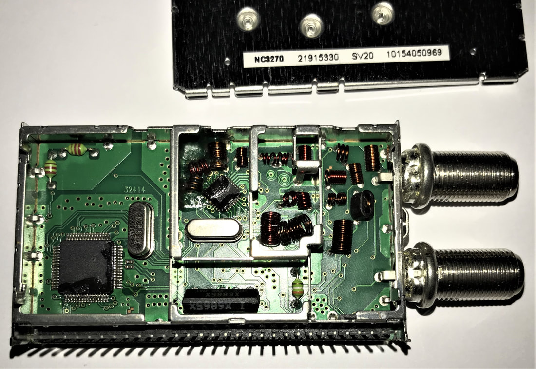
The former Philips/NXP CU1200-Mk3 family of digital cable NIMs was continued by Nutune as the NC3270 family, as far as can be seen without any significant component change. This module was produced in week 15, 2010.
|
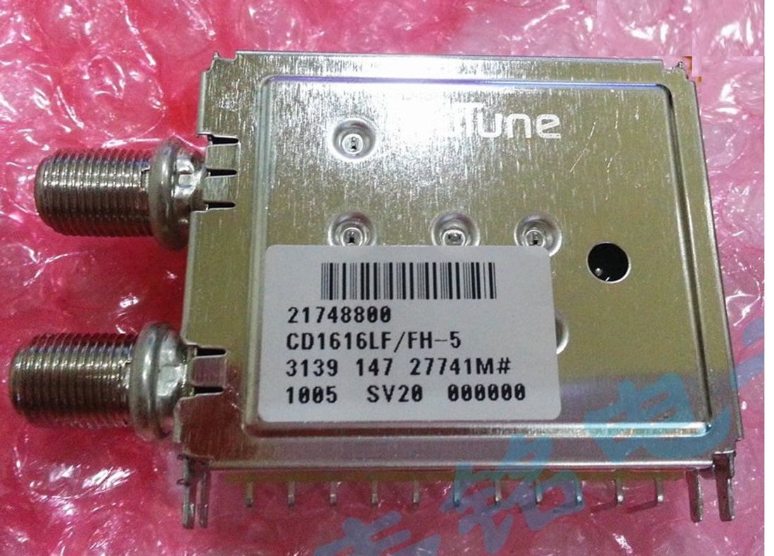
Not all products were re-named from the old Philips/NXP naming to the new Nutune naming convention. This CD1616, while produced in week 5 2010, still carried the original type name, the Philips 12nc (3139 147 xxxxx indicating a Singapore tuner) but also the new Nutune ordering number (21748800).
|
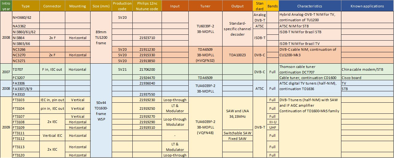
A non-exhaustive overview of some of the main products of Nutune based on original NXP RF Solutions modules (and one Thomson cable tuner).
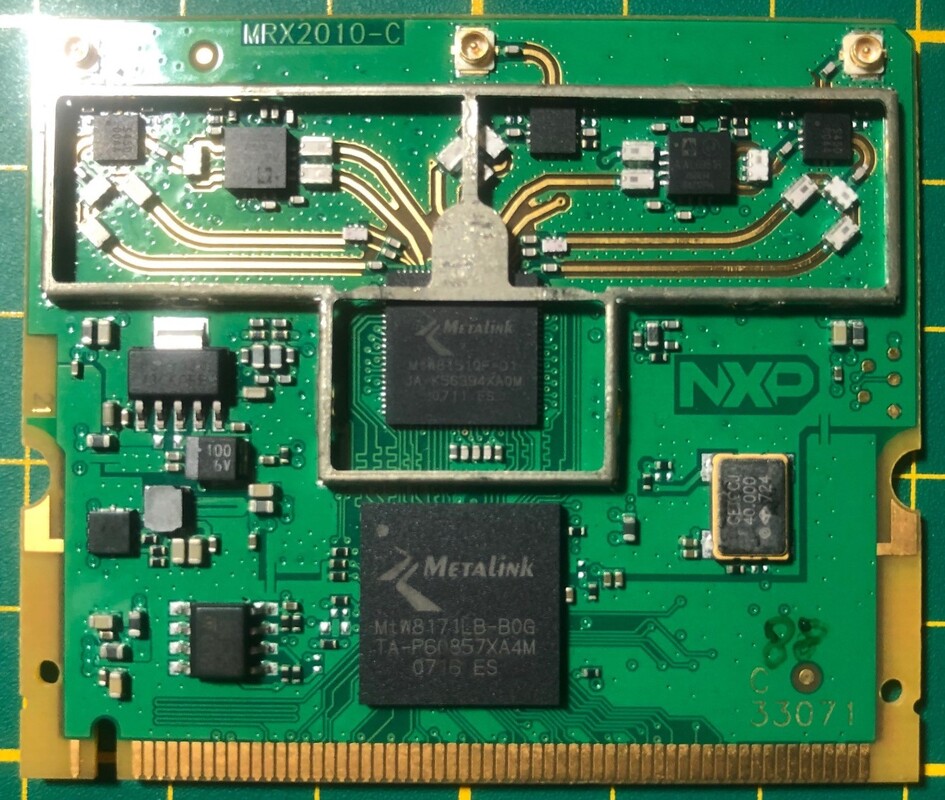
One of the remaining developments in Eindhoven had been the MRX2010 Wifi module, including the new 802.11n 5-GHz MIMO extension. The module was ready for production, and received FCC-approval in October 2008. It is doubtful it was ever produced, given that all experts in Eindhoven had been fired. [Detlef Marbach collection]
|
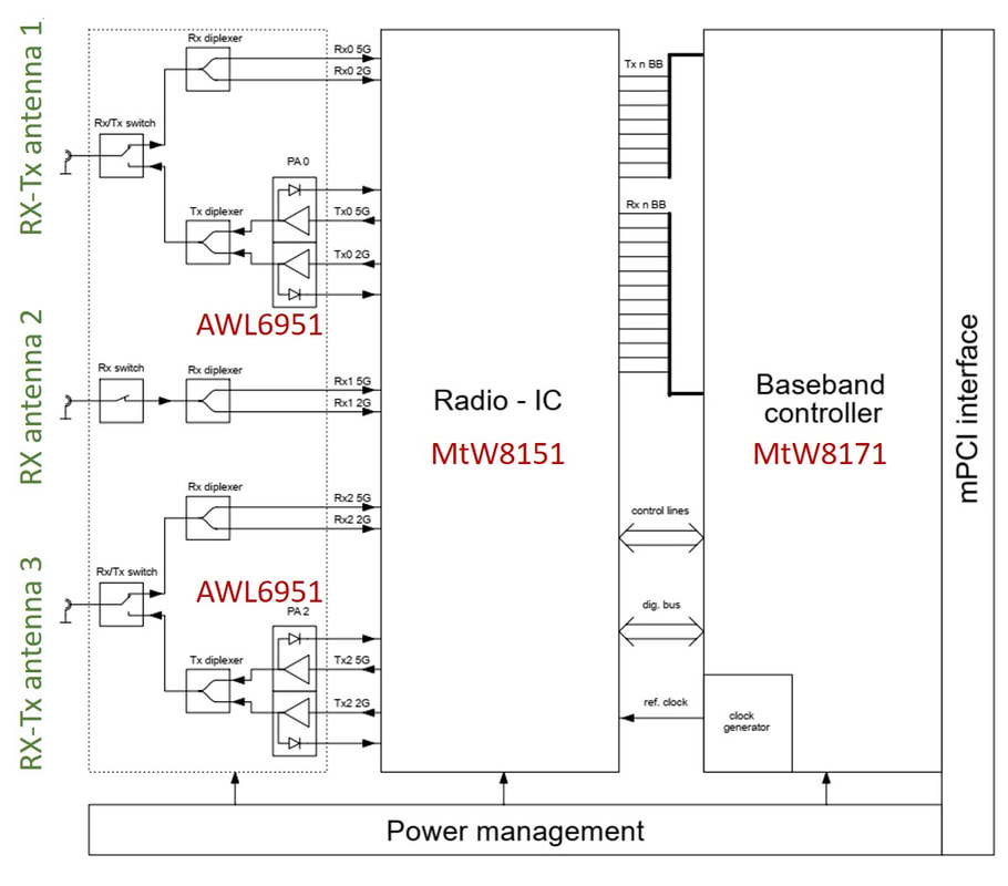
The MRX2010 was based on the Metalink MtW8151 triple radio and MtW8171 MIMO baseband ICs. It used two Anadigics Power Amplifiers and multiple diplexers and RF switches. With around 25USD sales price it was the most expensive product of RF Solutions at the creation of Nutune. [MRX2010 Manual, 2008]
|
Nutune started on the wrong footing from the beginning. To start, establishing a new company in the market takes time, while it immediately lost the premium label of being "Philips-Quality". Especially in China, where NXP and Thomson had been fierce competitors and were seen as alternative sources, where now all of a sudden a single company and many customers looked for another 2nd source. So the combined company quickly lost serious market share in China. But the most important problems were related to the company cultures, which were quite different in Philips/NXP and Thomson. Although Pieter Paumen invested a lot of energy into creating a single team, in practice there were still many islands and a lot of mis-trust. Also the classical title and salary inflation took place to avoid key people from walking away, while the company had to establish all functions that were normally covered by the large mother company (fiscal, legal, etcetera). All in all the bottom line was simple: less sales and more costs. Almost immediately after the creation of the JV sales in the 3rd and 4th quarter of 2008 almost halved, bringing the 2008 sales down to only 180Mio$. So in six months the sales growth from the joint venture had evaporated! NXP management, which had to consolidate the financial results, was shocked.
By May 2009 Pieter Paumen was replaced as CEO by Mark Foley, the first time an outsider became the tuner business leader. He essentially got the assignment from the NXP management to asses the viability of the Nutune JV and advise on the best way forward. To start, he reduced the sales outlook for 2009 to 100Mio$. With now a portfolio of only tuners, and no new higher margin products to compensate for the price erosion, this should have been no surprise. But unexpected or not, a next round of restructuring followed, resulting in the closure of the headquarters and development site Eindhoven. After 60 years tuner activities had stopped in the Netherlands too. Also Villingen and Singapore R&D were cut back to the bare minimum, leaving only 11 engineers at each site. The remaining non-tuner developments were stopped, while the ATOP automotive GSM module was transferred to the BU Automotive in Nijmegen. With this skeleton crew Nutune ambitions had to be reduced, obviously, and the strategy became focussed on an two tracks: cable multi tuner modules, which was the focus of Villingen, and aggressive size reduction of tuners, driven from Singapore. Because these two tracks were almost independent the interaction between Villingen and Singapore remained minimal.
By May 2009 Pieter Paumen was replaced as CEO by Mark Foley, the first time an outsider became the tuner business leader. He essentially got the assignment from the NXP management to asses the viability of the Nutune JV and advise on the best way forward. To start, he reduced the sales outlook for 2009 to 100Mio$. With now a portfolio of only tuners, and no new higher margin products to compensate for the price erosion, this should have been no surprise. But unexpected or not, a next round of restructuring followed, resulting in the closure of the headquarters and development site Eindhoven. After 60 years tuner activities had stopped in the Netherlands too. Also Villingen and Singapore R&D were cut back to the bare minimum, leaving only 11 engineers at each site. The remaining non-tuner developments were stopped, while the ATOP automotive GSM module was transferred to the BU Automotive in Nijmegen. With this skeleton crew Nutune ambitions had to be reduced, obviously, and the strategy became focussed on an two tracks: cable multi tuner modules, which was the focus of Villingen, and aggressive size reduction of tuners, driven from Singapore. Because these two tracks were almost independent the interaction between Villingen and Singapore remained minimal.
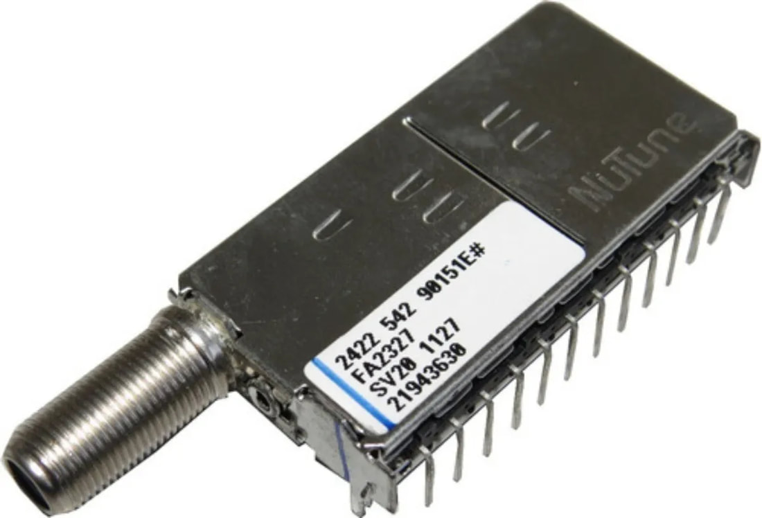
The Nutune FA2327 ATSC/ISDB-T half-NIM. Note the new frame with 12 pins and the long F-connector.
|
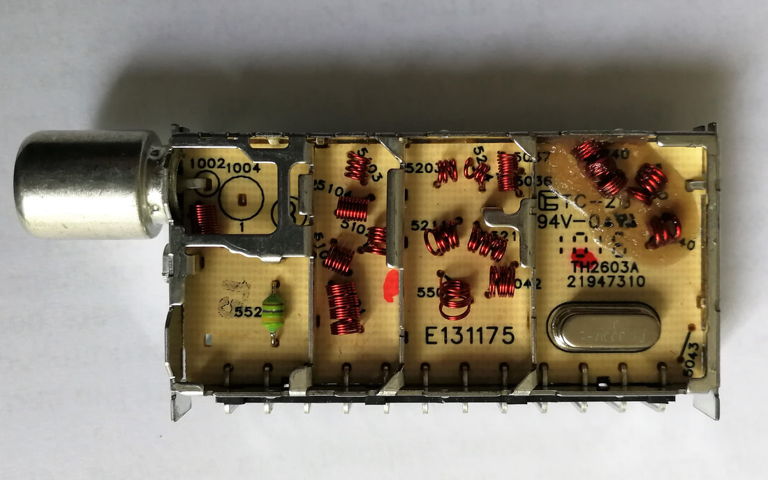
The Nutune TH2624 hybrid off-air tuner. The frame design and printed CEM PCN clearly indicate this was not an RF Solutions design. [Pieter Hooijmans collection]
|

The SMD component side of the Nutune TH2624, with the NXP SSOP38 TDA6651 MOPLL as most dominant component. [Pieter Hooijmans collection]
|
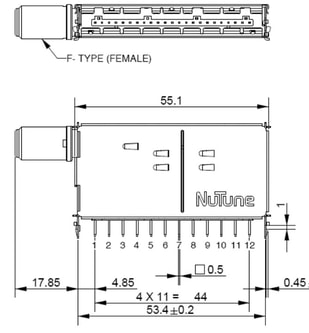
Mechanical outline of the Nutune FA2328. Pin spacing is still according WSP but mechanics not. [FA2328 Data Sheet, 2010, via Chee Eng Soon and Toh Kong Lim]
|
The first generation products developed under the Nutune name were the TH2600 hybrid tuner and FA2300 digital terrestrial half-NIM. (Nutune marketing consistently called the digital tuners with SAW filter and first IF AGC as "half NIM", a rather confusing and misleading name but apparently accepted in the market). Like the NXP 1100 generation they discarded with the WSP standard, and defined a new frame: 62 by 31mm with 12 instead of 11 pins. The pin distance still used the WSP 4mm spacing. The TH2600 tuners used the NXP TDA6651 MOPLL, while the FA2300 the Infineon TUA6037. The only known interior picture shows single-sided PCB with component identifiers printed, suggesting a Villingen design. Which makes sense, because the remaining NXP crew in Singapore was fully loaded with rolling out the FQD, CD and TD1100 families. It is also plausible that Thomson was already working on this smaller size generation at the time of the merger.
|
|
Apparently Nutune had not lost the connection with Philips TV, because the modules became part of the standard tuner set for the new TV550 platform chassis Q551 and Q552 that were launched in 2010. Although as before competitor tuners were used too, the TH2603 hybrid NTSC/ISDB-T tuner was used in the Latin-American versions of the chassis, as well as the FA2307 half-NIM. The FA2327 was also used in one of the TPV chassis for South America, the TPM5.1. The same year a modified generation came out, the FT2100 and FH2600, with twice as many pins (25) at half the pin spacing. At the same time a shorter 47mm frame allowed 17 pins. Noteworthy is that Nutune was no longer an internal supplier to Philips - in contrast to NXP, which kept the same 12nc Philips coding system - and the Nutune modules therefore were coded with the 2422 542 xxxxx 12nc's identifying them as 3rd party RF products. (Still the same codes as used in the Elcoma period, it was a very consistent system!)
|
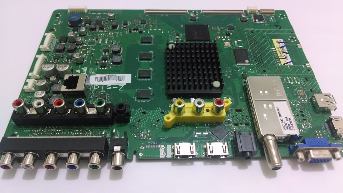
The Nutune FA2327 ISDB-T half-NIM on a Philips Q555 chassis for Latam, the 40PFL6615 TV set. The reason for the long F connector is obvious.
|
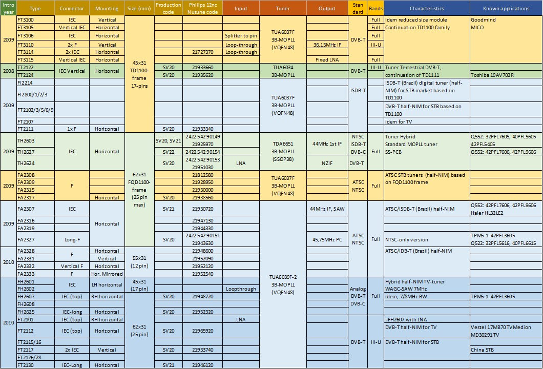
An overview of the known Nutune modules based on MOPLLs and based on the NXP 1100 families frame.
FRH2000 and FQD1100, the last multimedia families, 2009
Over the last ten years or more the BU Tuners and BL RF Solutions had been making many different products, but all of them using the standard 1200 (Philips) and 1300 (WSP) frames and pinning, with only the length of the module, and therewith the number of pins, as a variable. In the Philips tuner strategy backward pin-compatibility with previous generations had always been an important element. Miniaturization did take place, but essentially by putting more functionality into one of the existing frames. A good example is the TD1300F, where the LNA-diplexer, the tuner and the IF SAW plus VAGC were step-wise squeezed into a standard 50mm 1300 WSP frame. Similar trends were applied to the CD1300 and FQ(D)1200 families. However, this strategy could not be applied forever, and competition started to release smaller modules, driven by e.g. the ever smaller size of the key components (HVQFN-style IC packages, 0402 SMDs and 0603 transistors and diodes). RF Solutions therefore also needed a smaller sized family.
The discussions to come to a smaller mechanical module structure did not go easy, since mixed with the application-driven functionality to fit into the mechanics. The first trial was the 2000 family, which started in 2006. The FRH2000 family targeted the following functionality:
- a full-band hybrid analogue-digital front-end based on the new Philips Semiconductors Master-IF. All PAL, SECAM plus DVB-T conversion to (N)ZIF in the FRH2016ME. Infineon TUA6034 for good phase noise.
- For the NTSC and ATSC/QAM US version the Master-IF was too expensive, and the older TDA9885 AFRIC was used. This had as consequence that in this case the digital IF SAW filter and Sanyo VGA were again required. A Japanese FRH2086 could easily be derived.
- FM-radio using the standard dual-input from the FR1200, an IF of 38,9MHz and demodulation in the Master-IF.
- Wireless Remote Control (RC) receiver using a narrow band 433MHz receiver based on the TDA6509.
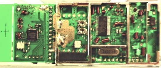
Not very good but unique picture of the FRH2016ME prototype in its new frame. On the far left outside the frame the 433MHz RC receiver. Due to the very low frame the SAW filters had to be bended, as previously in the FQ1200-Mk4. [FRH2000 PRS document, March 2006, via Edward Ng]
|
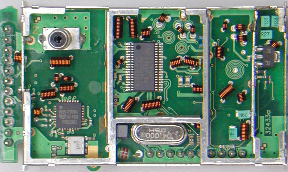
Picture of the TWH2016 prototype, only containing the tuner and wireless receivers. Both MOPLLs are visible. Note the vertical pin row on the left. [idem]
|
Although the FRH2000 project was started early 2006 it never passed the Design Release gate, mainly due to troubles with the new Master-IF and SAW filter performance. The Remote Control also gave many headaches with respect to RF approbation. The project was stopped, and the Master-IF was introduced, with delays and after a re-design, in the FQD1200CME-Mk5 the next year, which has already been presented.
Discussions around a smaller and thinner frame did not stop there, however, but it took till end of 2007 for the next round. In the meantime, RF Solutions had become NXP, and gone through another round of restructuring. In the market it had become clear that the PC Multimedia convergence was not going to be in the direction of multi-standard and hybrid tuners in PC Media Centres, but that everything would become streaming content. In contrast hybrid frontends were increasingly used in low to mid end TV, but much less feature-driven than the PC market. TV wanted small size and lowest cost while the module should cover the required standards. This became the 1100 family, slightly bigger than the 2000 concept because the TV world was less size driven than the PC card world.
Discussions around a smaller and thinner frame did not stop there, however, but it took till end of 2007 for the next round. In the meantime, RF Solutions had become NXP, and gone through another round of restructuring. In the market it had become clear that the PC Multimedia convergence was not going to be in the direction of multi-standard and hybrid tuners in PC Media Centres, but that everything would become streaming content. In contrast hybrid frontends were increasingly used in low to mid end TV, but much less feature-driven than the PC market. TV wanted small size and lowest cost while the module should cover the required standards. This became the 1100 family, slightly bigger than the 2000 concept because the TV world was less size driven than the PC card world.
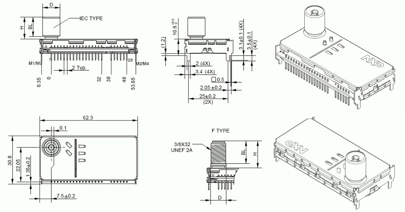
New mechanics of the FQD1100 family. On the right the two mirrored horizontal mounting versions. [via Thomas Fenkes]
|
The 1100 was essentially a mechanical standard only, with the following main characteristics:
|
The first three elements were not dramatic and could easily be handled. The mirrored versions, however, was a major issue with respect to type diversity. Seven different frames were required: the normal and mirrored versions of three different horizontally mounted frames: single input, dual input and vertical connector. And the single vertically mounted frame. These different frames also required serious modifications of the alignment and test jigs in P3 operations. What makes it all the more surprising is why this was deemed so important. Which application requirement made it important to have the pin row on the left side instead of the right side of the frame?
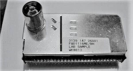
The NXP FQD1116ME/BH. In this (lab sample from April 2008) B-side with large components is above. The production ramped mid 2008.
|
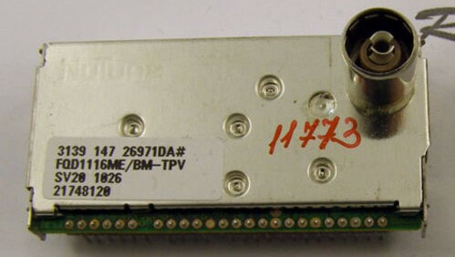
The same product, but now as mirrored version FQ1116ME/BM in production (wk26 2010). In this version the same PCB is flipped, and now the SMD A-side is on top.
|
Electrically no dramatic changes were introduced in the FQD1100. Even more stringent than in the predecessor FQD1200-Mk5, there were only two basic types: the FQD1216ME Multi-Europe PAL/SECAM with DVB-T ZIF output, and the FQD1136 NTSC model with 1st IF ATSC output. The 1216ME re-used the TDA9899 Master-IF IC introduced in the FQD1200C-Mk5, still labeled as RFS5 to mislead competition. The IF IC covered all analogue standards as well as the DVB-T down conversion to (Near) Zero-IF, and the previously standard digital IF SAW filter and Sanyo VGA could again be deleted. However, this solution was deemed too expensive for the single standard FQD1136 model, which fell back to the previous generation Alignment Free AFRIC IF-IC, the TDA9881. As a consequence, the 1136 did require a SAW and Sanyo VGA. Because of the different phase noise requirements, the 1116ME and 1136 also continued to use different MOPLLs: the TDA6651 fractional-N for DVB-T and the new Infineon TUA6039 for ATSC. The input circuitry was common and used the BF1201 (VHF) and BF1202 (UHF) MOSFETs for further improved noise performance. In 2010 an updated version with LNA (FQD1116AME) was released.
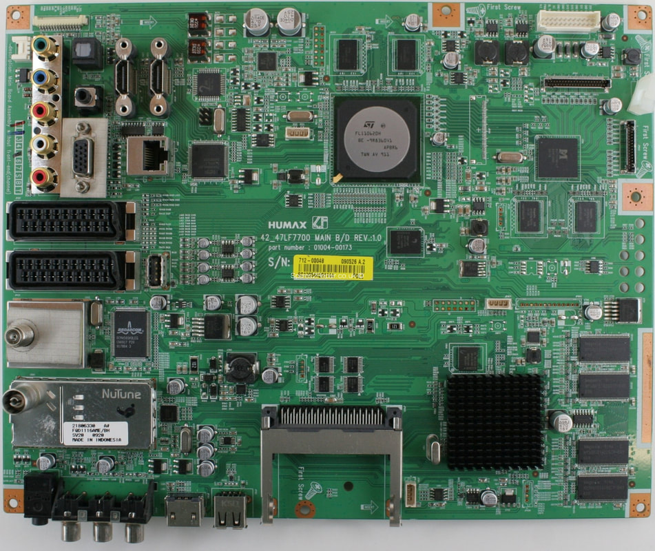
The NXP/Nutune FQD1116AME/BH on an LG (and Humax) 42LF7700 TV board.
|
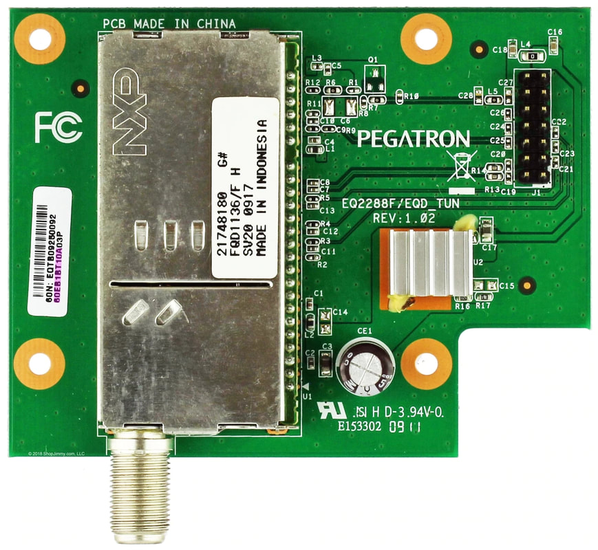
Hybrid TV add-on card of the Taiwanese ODM Pegatron, based on the FQD1136/FH, one of the rare versions with a classical side connector.
|
The FQD1100 development started still under NXP, and the products were released mid 2008, just before the formalization of the Nutune JV September 1st. However, production was under Nutune, and most products can be found under that brand. By this time the main application of the (hybrid) frontends had moved away from PC Multimedia to low/mid end TV. Quite some Japanese set makers like JVC, Sanyo and Hitachi used these modules in their smaller screen size LCD TVs. TPV, now developing the low end Philips LCD TVs, also used the FQD1116ME in its TPM2.1 to 5.1 chassis, although not as the primary tuner since many LG modules are seen too. The interesting conclusion is thus that, since the 1990s FQ900 TV frontends, Philips TV always refused to use Frontends (Tuner plus IF) let alone NIMs, once their development was taken over by others, TPV in this case, frontends appeared inside the chassis. Apparently, it was not such a bad solution after all!
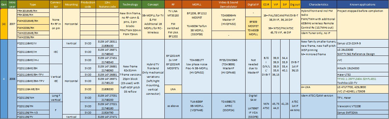
Overview of the NXP FRH2000 and FQD1100 hybrid frontend families. The first one was never released. The FQD1100 in contrast was very successful in standard LCD TV of Asian TV makers. The FQD1100 was sold most of the time under the Nutune brand. The first FQD1116ME in the list is the product with the highest known 12nc number, and thus the last product coded in the Philips/NXP coding system.
|
With the FQD1100 comes an end to the almost 20 years of Philips - and the last two years NXP - RF Frontend business. It started with the big and expensive (35-50Hfl) FQ800 and FQ900 familes for high end TV, but with a very unwilling BGTV customer. The FI1200 and later FQ1200 PC Multimedia fronteds were, however, from the beginning a big success. Initially not in absolute volumes, but Philips Tuners took a leading market share of around 60-65% from the start, which it never gave away thanks to a continuous stream of innovative upgrades: multi-standard, FM-radio (a major hit!), quasi split sound IF and later hybrid solutions for many combinations. However, after the recovery from the 2001 internet bubble, the PC MultiMedia segment really took off, becoming 45-35% of the total RF Solutions sales. And when TV-on-PC started to decline after 2005, LCD TV took over. From that perspective it is a big question why Nutune did not continue this segment, making the FQD1100 the last Frontend family.
|
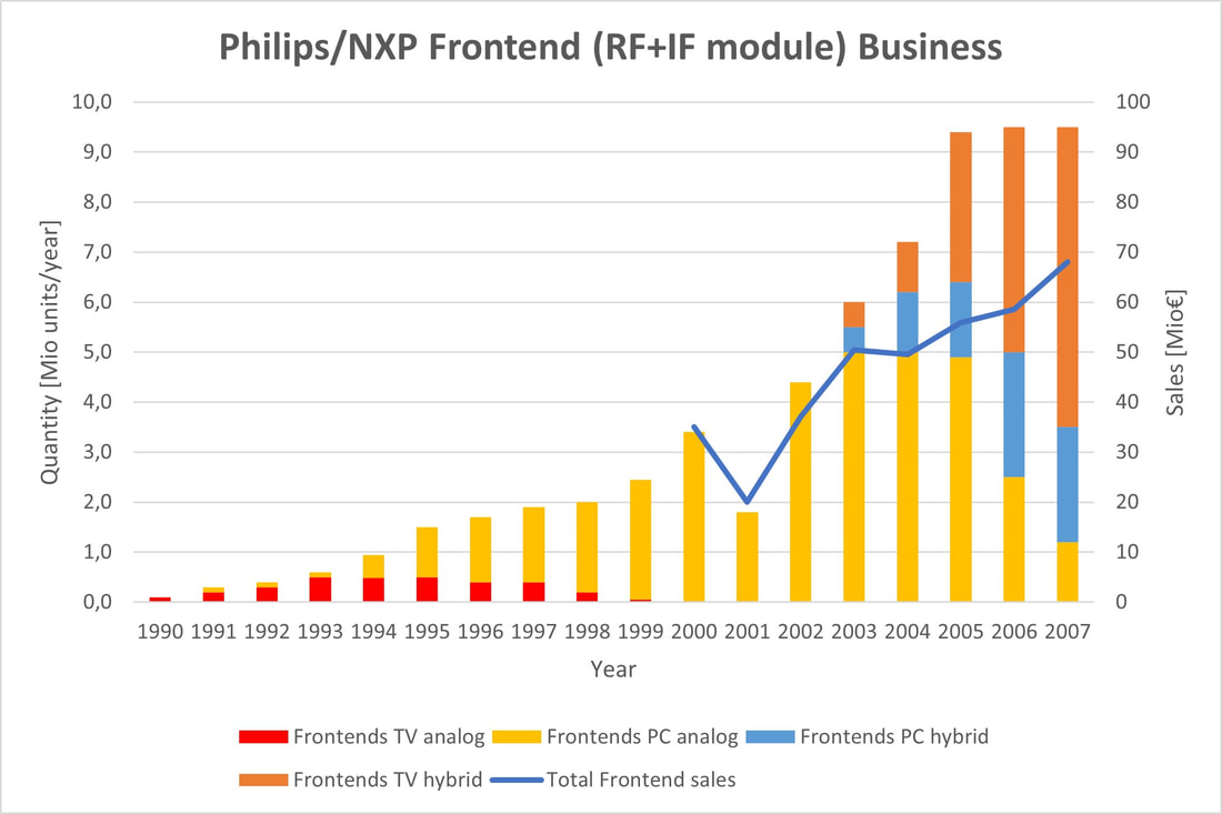
Volume history of Philips/NXP TV and PC Frontend sales from the introduction in the end 1980s till 2007.
|
CD1600 and CD1100, the last digital cable tuners, 2006-2008
Developments for cable tuners essentially followed those of terrestrial. The cable tuner function differed in only one aspect from the off-air tuner: it featured a wideband buffering LNA to properly terminate the cable impedance across the full band, as opposed to the off-air tuner that used a real LNA to improve weak signal reception. Although they were both called LNA, the cable LNA was optimised for non-linear performance (good CSO and CTB) whereas the off-air LNA was optimised for NF. A second difference was that cable tuners often contained a modulator to re-modulate the digitally received signal to an analog carrier for in-home distribution. The CD1300-Mk1 to Mk3 cable tuners discussed so far all used the long WSP frame of 65mm to accomodate for the more complex LNA-loopthrough-modulator input section.
|
However, also the cable tuners were forced to follow the size reduction set in by the TD1300F, where the entire tuner was squeezed into the standard 50mm WSP frame. In practice this was combined with the switch to the 1600 frame with the mounting hole, and the first version was the CD1686F-Mk3, a Japanese cable tuner without any LNA, loop-through or modulator. For compatibility with NTSC tuners, it re-used the standard US IF of 45,75MHz analogue and 44MHz digital. The first full generation was the CD1616LF-Mk4, effectively a redesign of the CD1316L-Mk3 into the smaller frame. It continued to use the Philips (now NXP) TDA6509 MOPLL. For size reduction the Sanyo IF VGA becoame the LA7796 in an SSOP8 package, while the LNA-loop-through became a single Toshiba MT3S150P wideband transistor.
The main application of these tuners were the DVB-C European and Asian, especially Chinese, cable modem and cable STB markets, with many different local players. Competition in thse markets was fierce, also because there was not much featuring possible in these tuners. Within the Mk4 the only option was the internal wideband-AGC. (The real value added featuring happened in the CU1200 cable NIMs, which continued to run quite successfully in parallel). By this time a TD1600 cable tuner was only slightly more expensive than a standard off-air tuner, with market prices around 2,50USD. |
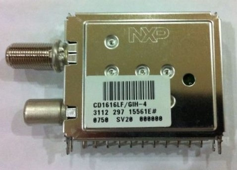
An NXP CD1616LF/GIH-4 hybrid cable tuner, the main runner from this generation. CD= Cable Digital, 1600= frame with mounting hole, 16= PAL/DVB-C type, L= RF loop-through, F= short 50mm frame, G= long-F input connector, I= IEC output connector, H= horizontal mounting, 4= Mk4. This module was built in Batam (SV20) in week 50 2007.
|
It turned out that the step to the CD1600F was not enough, the market asked for even smaller solutions. This was then translated into two parallel developments:
- the CD1100, a standard CD1600 cable tuner function in the new (short) 1100 frame.
- the CDM1600, with now also the modulator squeezed into the standard 50mm WSP frame. This required a change of key components.
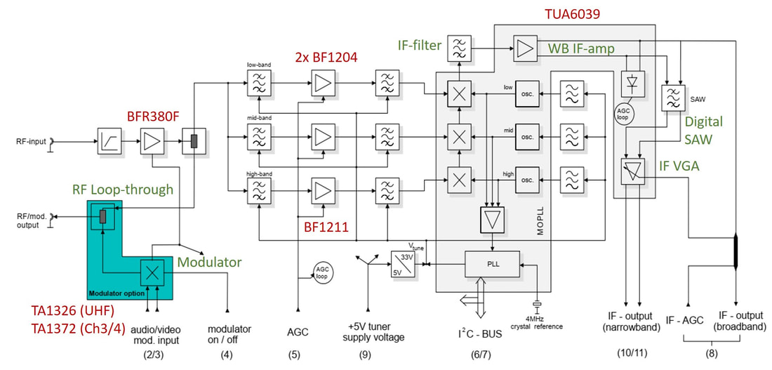
Block diagram of the NXP CDM1600LF-Mk5 cable tuner-modulators. The wideband IF output (unfiltered analogue IF) and the external input for the IF AGC (usually coming from the channel decoder) share the same pin 8, where the signals are separated using a LPF for the IF signal. [CDM1636LM-Mk5 Preliminary Data Sheet, October 2008, via Thomas Fenkes]
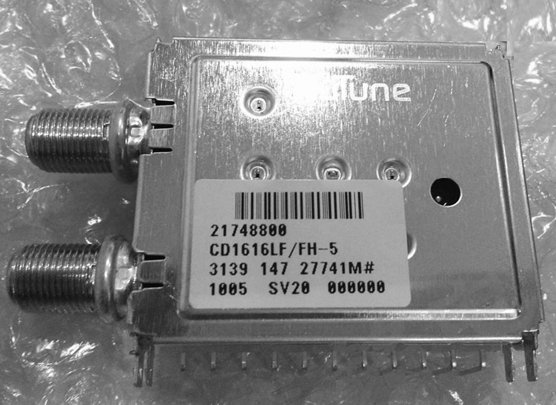
The CD1616LF-Mk5 ran for a number of years in production. This module was produced week 5 2010 by Nutune.
|
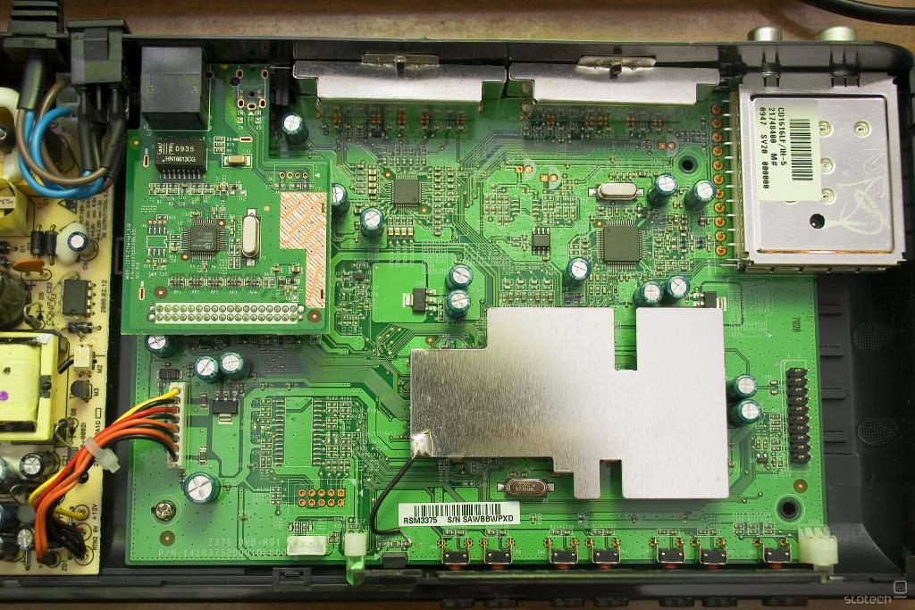
The NXP CD1616LF/IH-5 inside a Cisco cable STB.
|
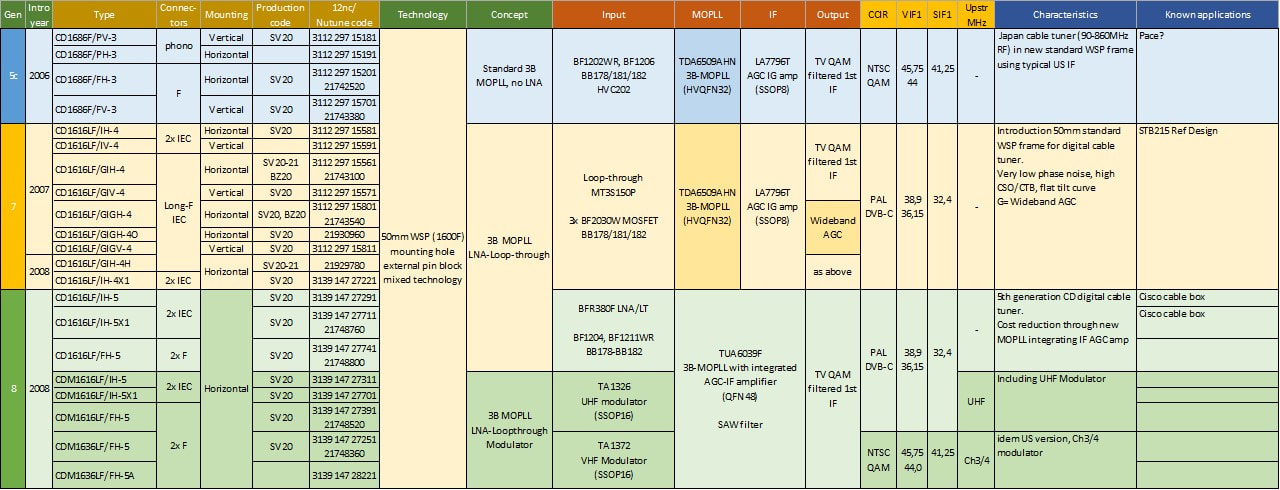
Overview of the Philips-NXP-Nutune CD1600-Mk3 to -Mk5 families. All modules were produced in Batam (SV20). Most customers were in the Asian and European cable modem and STB market, including many smaller companies that are difficult to trace back.
|
Parallel to the CDM1600-Mk5 the CD1100 was thus developed, using the short version (45mm length) of the new 1100 mechanical frame design. It was essentially the CD1616-Mk4 ported to a new frame size and a new technology. Apart from the broadband LNA, which once again changed, this time to the NXP BGW540W, the TDA6509 MOPLL and LA7796 VGA remained unchanged. One of the main technology changes with the 1100 family was that the mixed wave-reflow technology that had been used so successfully for ten years was replaced by a modified 1200 double-sided reflow process. The main reason for this was that it allowed ICs to be placed on both sides of the PCB, and the Sanyo VGA was indeed moved to the A-side.
The main versions were the CD1116AL with LNA and loop-through, whicle similar to the CD1300 and C1600 a CD1100ALS (RF out via pin) and CD1116/R (RF in via pin, no LNA) "Twin Tuner" pairs were available. The CD1100 was the last digital cable tuner developed by Philips/NXP and was ramping when RF Solutions became Nutune, and most modules are found under that brand name. |
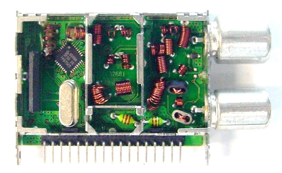
The NXP/Nutune CD1116AL/IV hybrid cable tuner top view (B-side). The tuner uses the new short 45x31mm 1100-frame. Especially the leftmost compartment has become very crowded with the TDA6509 MOPLL, SAW and crystal, and the Sanyo LA7796 VGA has consequently moved to the A-side.
|
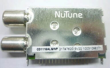
The Nutune CD1116ALS/IVP, part of a Twin-Tuner set with the CD1116/RV. Note that the former NXP 12nc is no longer carried. This module was produced week 3 2010 in Batam.
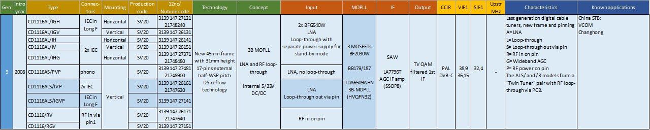
The NXP/Nutune CD1100 family of digital cable tuners in the new 45x31mm 1100 frame.
The last digital off-air tuners, 2006-2008
The developments for the Digital Terrestrial tuners were not different from those in Digital Cable, with the same price pressure, roughly the same sales prices around 2,50USD and declining, and the same need for smaller modules. However, in the TD portfolio one interesting development took place that was not copied in Digital Cable: the TD800 and TD900. At this moment I still have no information on the TD811, but assume that it was verysimilar to the TD911, of which at least some things are known. The TD911 - the only type that made it to production - was the next, and final, effort to make a tuner using Automatic Tuner Alignment (ATA). Back in 1990 it had been seen as the next step in tuner cost reduction, but the UV936AA never made it beyond the prototype stage. The basic idea remained intact: store the actual tuning curve data (the required optimal tuning voltage for the pre-stage and BPF at a given frequency) in an EEPROM and read that data when setting a tuner frequency. The potential advantage was that no longer manual alignment of the tuner coils was required, a cost reduction given the many manual alignment steps. That was 1990. By 2006 the main reason for using ATA was that the coils could be fixed and very small, even embedded in multi-layer PCBs. Infineon took the step to develop an ATA MOPLL, the TUA6041 Lightning, clearly focussed on the then "hot" TV-on-Mobile application. The TUA6041 was therefore also fit for the 1,5GHz L-band, and was amongst others used by RF Solutions in its PDD3016 DVB-T module for portable consumer applications.
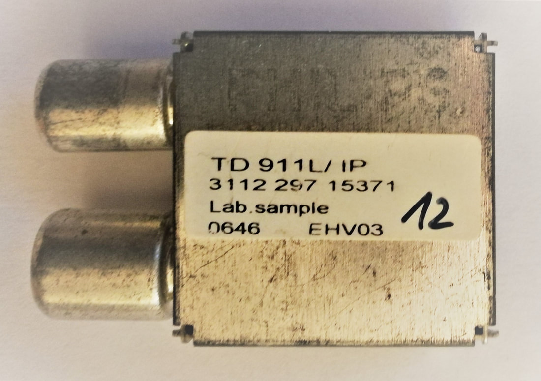
The unique TD900 module, the smallest ever developed by Philips. Size was 30 by 30mm and a thickness of only 7mm. As the label says, this was a lab sample from Eindhoven, week 46 in 2006. [Jan van Daal collection]
|
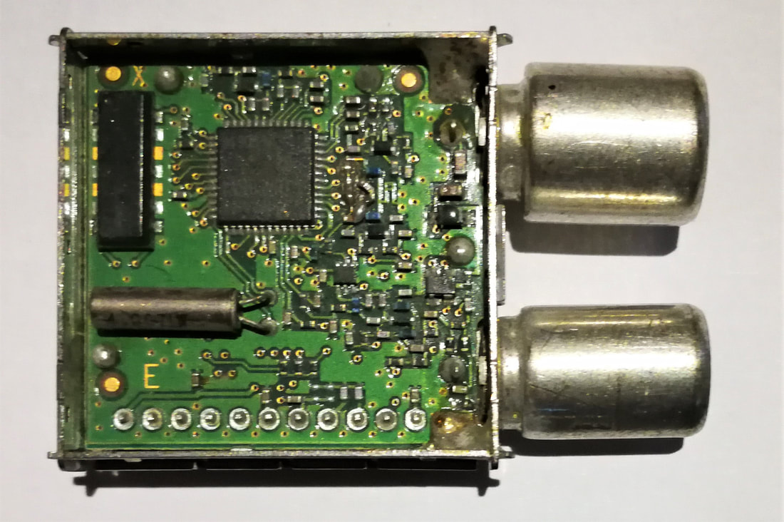
Top B-side interior view of the TD911L/IP with an SMD SAW filter (left) and watch crystal below. Note the total absence of air coils. [Jan van Daal collection]
|
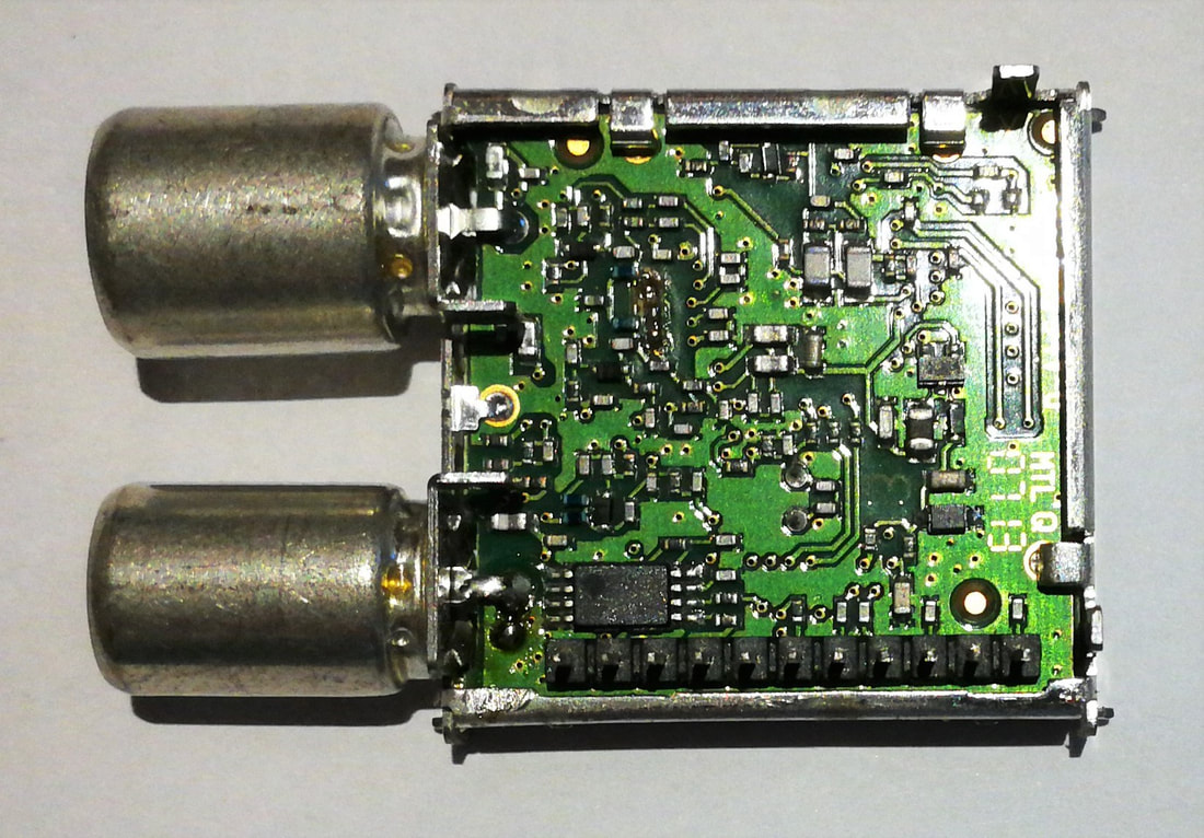
Bottom A-side interior view of the TD911. Lower left the 8-pin SSOP EEPROM. On this side also no air coils, all inductors are on the inner PCB layers. [Jan van Daal collection]
|
The TD911L thus had the follwoing main characteristics:
- 2-band off-air tuner (911) with RF loop-through (L)
- TUA6041 3-band MOPLL (only VHF-III and UHF used) with embedded DACs for tuning voltage, and I2C-controlled EEPROM with tuning data. The MOPLL also had the digital IF VGA integrated, so only an external SAW was required. This was an expensive low-profile SMD SAW.
- To fit everything into a 30 by 30mm frame it used a QFN IC, 0402 SMDs and double-sided reflow soldering.
|
The mainstream TD1600 ran in parallel with the CD(M)1600-Mk5 and used the same key components:
|
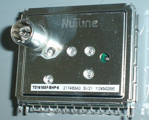
A Nutune-produced TD1616EF/BHP-5. This module (production status 21) was produced in Batam week 24 2011, so must have been one of the last produced there before it all came to a standstill.
|
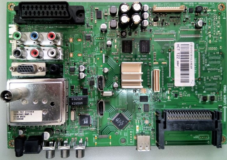
One of the big users of the TD1600-Mk5 was Beko, in Turkey, which produced Beko, Arçelik and Grundig-branded sets from the same 190 platform.
|
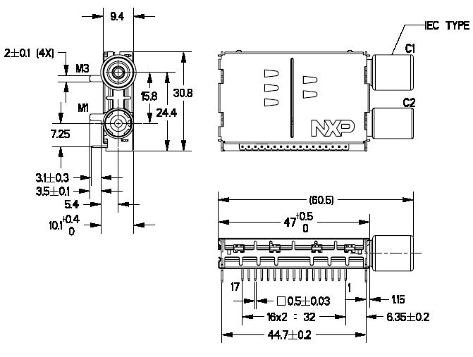
Mechanical outline of the TD1100 digital off-air tuners. [TD1136 Data Sheet, 2008, via Lim Kui Yong]
|
The final digital off-air family developed by NXP was the TD1100, again running in parallel and very much identical to the CD1100. However, because the off-air volumes were so much larger (roughly 10x) the diversity in the TD1100 family obviously also was. The basic model was the TD1100AL, with DVB-T full band (TD1116), DVB-T off-air (TD1111) and ATSC (TD1136) versions, and a number of by now standard sub-versions for Twin Tuner pairs (ALS with the loop-through out via a pin and /R with the RF input on a pin). To meet the DVB-T phase noise requirements it used the latest Infineon TUA6037 3B-MOPLL which also integrated the IF VGA. Although from a specification perspective not strictly necessary due to the more relaxed ATSC phase noise requirements, the ATSC version used the same MOPLL, thus allowing a single design. However, it seems the TD1111 2-band model was the most widely used version.
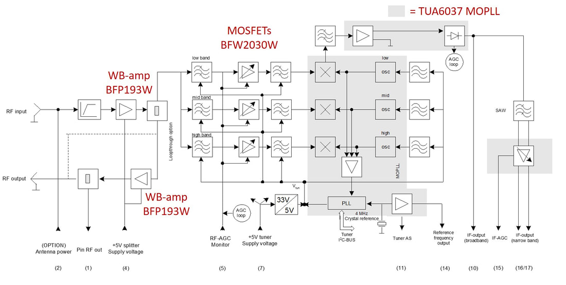
Block diagram of the TD1100AL, with wideband input amplifier (A) and RF loop-through (L). [TD1100A(L)(S) Objective Data Sheet, October 2007, via Lim Kui Yong]
|
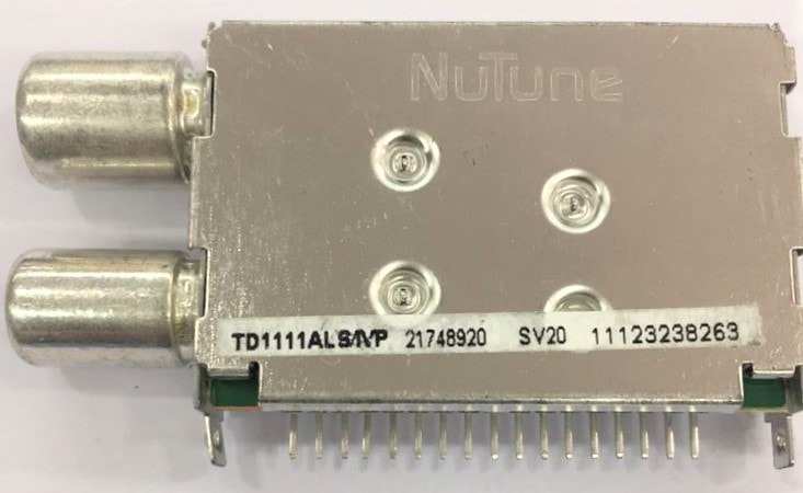
One of the most seen models of this family, the TD1111ALS. This is the 2-band off-air DVB-T Twin Tuner half with loop-through output on pin1. Most TD1100's were sold under the Nutune flag.
|
|
With the TD1100 we have reached a sad but historic milestone: the last family of tuner modules developed and produced by Philips or NXP. From this moment onwards all products would be from the Nutune JV. But it is appropriate to end with the TD1100, because this family of digital off-air tuners was extemely successful, replacing the main product of the BU Tuners and BL RF Solutions, the UV1300 standard analogue tuners, as the primary product of the business. And a spectacular replacement it was! In the year 2000 the UV1300 (Mk3 at that time) was the absolute main product, with some 13 Mio produced that year. That same year only a few handfuls of digital tuners were sold, the large but high-performance TD1500's. Only in 2003, so seven years after the BU Tuners had launched its first digital tuner, did a real market for digital tuners develop, linked to the breakthrough of large screen LCD TV. But from that moment onward it went fast: already by 2006 the volume of digital tuners had become bigger than the analogue tuners, with the Set Top Box almost 100% over on digital, but also TV now switching massively. By 2007, the last year with reliable numbers, the TD1600/1700 digital tuner volumes were 85% of the tuners and 55% of all products sold by RF Solutions.
|
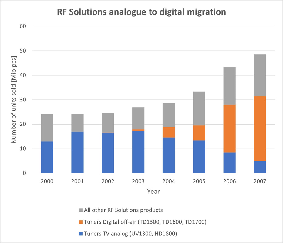
The volume share of Philips/NXP tuner business for standard analogue (UV1300 and the last HD1800) tuners and digital off-air tuners (the TD1300/1600/1700 families) during the years of the analogue switch-off.
|
A last observation that should be made, especially respectful to the BL RF Solutions, is the incredible volume growth of the last years: from a fairly stable 24Mio modules around 2000-2002, to 48,5 by 2007. And growing! As discussed earlier, that gave enormous challenges to the Operations of the BL, pushing increased outsourcing and fully loading of Batam and Suzhou. Throughout all these years the BL maintained a healthy 8-15% profitablility, a number I doubt was matched by most of the competitors. A large part of this volume increase was due to the integral market growth, with especially Taiwanese, Korean and Chinese new players, but in this fierce cost down and volume battle RFS was always able to stand its ground and maintain its market share. A major achievement, with the TD tuners (and the FQ1200 frontends) the core of it all.
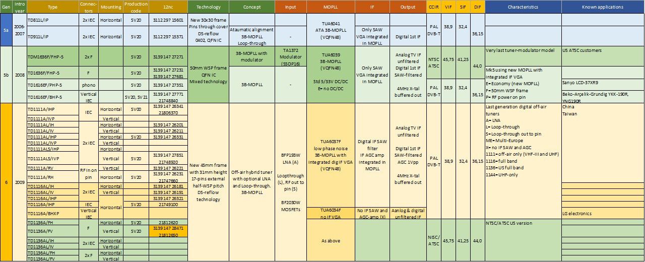
Overview of the last Philips and NXP TD900, TD1600-Mk5 and TD1100 Digital Terrestrial DVB-T and ATSC tuner families. The TD1136A/FV, marked in yellow, has the highest known 12nc number, and was thus the last of the hundreds of Philips and NXP products coded using this system.
NXP BU Home sold to Trident, 2009
|
September 1st, 2008, NXP moved its Mobile business unit to the new JV with ST Microelectronics, while per the same date the BL RF Solutions was put into the JV Nutune with Thomson Multimedia. The BU Home was now left as the only SoC large IC integrator within the company. At this time 90nm CMOS (C90, released around 2003) was the work horse of the company, while 65mm (C65, a standard TSMC node, released 2005) was used for next generation designs. The BU Home was the lead user of the new 45nm CMOS, where the PNX85500 was the lead product and the so-called "pipeline cleaner" for this complex and expensive CMOS node. Mid 2007 the PNX8541 was finally launched, the core IC of the TV520 platform. It was a 100mm2 IC in the Crolles 90nm node, while the derivative PNX5100 video co-processor was 70mm2 in the same technology. The TV520 platform and its derivatives were the core of the Q520 family of high-end TV chassis developed in Brugge, Belgium, the only remaining internal Philips TV development. In 2007 the Q523 was the first to be launched, followed the next year by the Q522, 528 and 529. In parallel the BL Digital TV was working all out on the next generation TV550 platform, due for 2009.
|
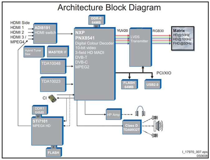
Block diagram of the 2007 Philips TV520 platform in the Q522 chassis, built around the NXP PNX8541 TV processor. Note that, apart from this core, only the receiver-related ICs are still from NXP: the TD1716 tuner, the TDA988x MasterIF, the TDA10048 OFDM and TDA10023 QAM channel decoders. And the class-D audio amplifier. [Philips Q522 Service Manual, 2008]
|
At this time the BU Home had a few structural problems, linked to its customer base and competition. In the analogue days Philips Semiconductors had been extremely successful with the One-Chip TV ICs, that were sold to many TV makers, giving Philips a 60% market share. Remember that Philips Semiconductors Consumer Business achieved 2,1Bio€ sales in 2000 and 1,6Bio€ in 2002. Unfortunately, this success was not repeated with the digital solutions, a playing field with new aggressive entrants: Taiwanese Mediatek as the leading competitor and Trident and Conexant as smaller players. On top of that Philips TV was rapidly losing its leading position too, suffering from the now Korean leaders Samsung and LG but also the many upcoming Chinese set makers. As described already, in 2005 all low end LCD TV developments were transferred to the Taiwanese company TPV, while all US TV developments for Philips went to the Japanese company Funai in 2007. But neither of these two companies felt any loyalty to the former Philips Semiconductors, now NXP, and they used almost exclusively non-NXP ICs, mostly around Mediatek core processors. In short, the BU Home was thus suffering from declining internal sales and reducing external market share. Or, from a different perspective, the new Digital TV sales (93Mio$ in 2009, 103Mio$ in 2009) did not grow fast enough to compensate for the much more rapidly declining analogue TV. These were the Ultimate One-Chip (mainly the TDA12000 and 15000 Hercules) which had once been close to a Bio$ sales but fell from 141Mio$ in 2008 to 76Mio$ in 2009. That year the TV business made a loss of 17% (EBITDA).
A second problem of the BU Home was the Set Top Box segment, which for the last years had been structurally declining. Philips, after the initial success of Digital TV Systems at the start of the decade, had - under the relentless cost reduction pressure of set top boxes - effectively given up the US (to Thomson) but also Europe (where it lost Canal+ as customer). Similar to the TV, the declining STB sales also impacted the NXP STB IC business, which had to leave leadership to ST (in Europe) and Broadcom (in the US). BU Home STB sales declined by 25% from 266Mio$ in 2008 to 199Mio$ in 2009. All this resulted in a dramatic year, with a 43% loss for the STB business.
So, although 95% of the management focus of the BU Home was devoted to the digital TV and STB businesses and their enormous challenges, in parallel 40% of the BU business was pure RF: in 2008 222Mio$ TV Frontend sales plus 187Mio$ from the consolidated Nutune sales! In total 409Mio$, not including the 8Mio$ internal sales from TV Frontend to Nutune. Of all BU Home businesses, TV Frontend was the only profitable one, making a healthy 15% EBITDA.
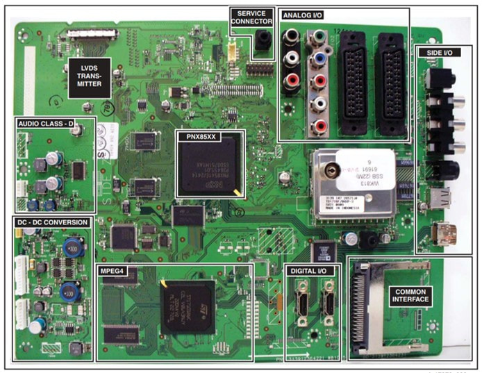
The Philips Q522 chassis board with the main components and functional areas indicated. Centrally the PNX8541, below it the ST MPEG4 decoder. The TD1716 with vertical connector could be mounted anywhere on the board. The two channel decoder and MasterIF ICs were mounted on the A-side of the board. [Philips Q522 Service Manual, 2007]
Rick Clemmer, with a history in TI and LSI Logic, had been waiting in the corridors and took over as CEO January 1st, 2009. With all the stock options he received from his friends at KKR he would cash 450Mio$ in the coming years. In the following months a new company strategy was defined, "High Performance Mixed Signal", which was the first time the strategy actually matched the core company technologies and competencies. At the same time, it was made clear that SoCs in advanced CMOS were no longer the focus of the company, and that selling the BU Home would be a logical conclusion. Because the businesses in which all money had been invested the past decade were now (almost) sold (BUs Mobile & Personal and Home), rapid growth could not be expected, and instead the target became to be the most profitable semiconductor player: all businesses were expected to make 25% or more EBITDA. Obviously, this could only be achieved by serious reductions in R&D. Difficult times ahead!
|
Mid 2008 KKR and its partners therefore played the same trick they had done a year earlier on the Mobile business: first an acquisition was made to camouflage the biggest weakness of the business, in this case STB. April 2008 it was announced that NXP acquired the digital TV and STB business from US company Conexant in a 110Mio$ cash deal. The deal was closed by August, Conexant bringing some 200Mio$ sales to the BU. However, it then became clear that this acquisition was only intended to prepare the BU Home for selling. This was too much for van Houten, who had his company roots in Philips Consumer Electronics and TV, and who furthermore saw his dream of being a Top3 semiconductor player completely shattered. He probably resisted the whole idea of selling the BU Home, and was subsequently fired over Christmas 2008. Although van Houten had business-wise clearly failed to grow NXP, his Philips bosses were still very happy with the 8Bio€ he had delivered them with the spin-out of NXP, and they apparently forgave him the rest. After spending two years under the radar at the Dutch bank ING (where, surprise, old Philips CFO Jan Hommen was now the CEO) he was, as per the original plan, proposed by the board to become the successor of Kleisterlee as president of Philips.
Rick Clemmer [FD]
|
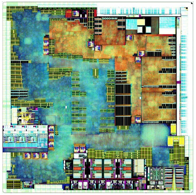
Die picture of the PNX85500 TV processing IC, the last SoC developed by Philips Semiconductors/NXP for the TV550 platform. Designed in TSMC 45nm CMOS, it contained a Trimedia core for 120Hz full-HD video processing with many picture improvement features, a MIPS controller, two 128Gb DDR2 and one 64Mb Flash memory interfaces. Essentially it integrated on one die the PNX8541/3, PNX5120 frame rate converter, the TDA10023 QAM and TDA10048 OFDM channel decoders and the TDA8296 digitized IF ICs of the predecessor TV520 platform.
|
At the same time the business of the BU Home kept declining. Where in 2006 sales had still been 988Mio$, it had, despite the acquisition of Conexant, declined to 641Mio$ in 2009. On the technical side the unit was also struggeling, since the TV550 platform was delaying. In fact, the first spin of the platform (M0) was cancelled and replaced by a scaled down M1 that contained one Trimedia and two memory controllers less. It would only be launched in 2010 as PNX85500 in the Philips Q551 and Q552 chassis. To fill the gap, in 2009 the PNX8543 interim solution was used for the Q543 and Q549 chassis. The PNX85500 was to be the very last TV processing IC developed by Philips-NXP during a 40 year period. (Remember that the first TV ICs were introduced in the 1972 K9 CTV set). It was also the last real SoC developed by Philips/NXP, which, after many billion dollars/euros investments in its "Going Digital" strategy had to admit defeat and was back to where it started: analogue-mixed-signal ICs.
It was therefore no surprise to most people that October 2009 the announcement came that the NXP TV and STB activities were sold to the US company Trident. The deal structure was interesting: instead of getting money for its business, NXP paid some 54Mio$ to Trident, in return receiving 60% of the Trident shares. So, effectively NXP paid to get rid of its Home business! The new JV was formally started February 2010. Unfortunately, for the people involved, the Trident-NXP marriage was not a successful one. The new company launched one more generation TV platform, the Fusion240, which was used in the 2012 QFU chassis from Brugge. But although Trident grew its top line, it never made profit, was not able to find new investors, and finally filed for Chapter 11 January 2012. The STB activites were subsequently sold to Entropic for 55M$, while the remaining TV activities went to Sigma Designs for 21Mio$. Another sad end to a once great Philips activity. |
There was one interesting side note in the BU Home-Trident announcement, especially from the tuners perspective. The official press announcement stated: "NXP keeps one important component for TV solutions: the design and production of silicon tuners. This is a profitable activity that belongs to what the company considers its core business: RF and mixed-signal". This meant that the BL TV Frontend and its tuner IC business stayed within NXP and moved to the newly created BU High Perfromance Mixed Signal (HPMS). By the time of the sale of the BU Home, the BU Multi-Market Solutions had become half of the company in volume (in 2009 1754Mio$, versus Home 641, Automotive 596 and Identification 382) and therefore was split into two new BUs: BU HPMS and BU Standard Products, the latter focussing on all discrete transistors and diodes business. BU HPMS clearly remained the largest of the company (1326Mio$ in 2010) with BU SP 848Mio$ that same year. With RF Solutions gone to Nutune, and channel decoding and TV ICs gone to Trident, this made the BL TV Frontend the last tuner-related business within NXP. However, a not unimportant detail in all this is that the Nutune JV, due to the majority share of NXP, was still consolidated under the BU Home and did not go to Trident, staying within NXP.
The end of Nutune, 2010-2011
After its creation, the JV Nutune initially had to focus on merging the two businesses, based on the existing tuner, frontend and NIM portfolios of both NXP and Thomson (which January 2010 changed its name to Technicolor SA, after its US subsidiary). Products continued to be produced as long as required by customers, in either the former NXP fab on Batam Island, the former Thomson fab next door, or the Suzhou Philips/Peacock JV. First generations new products mostly re-used the NXP 1600 or 1100 family mechanics and continued to use standard MOPLLs from Infineon or NXP. Because of the volumes still being produced, both Batam fabs remained essential at least on the short term, and both organisations were integrated into one. Which was a major issue, because as explained already, the organisational set-ups were fundamentally different. Philips and then NXP had always used temporary 4-year (but at least one-time extendable) worker contracts with every few years a major hiring campaign for a part of the staff. This kept the workforce young and allowed the workers to return to their families after 4-8 years with often a nice saving. Thomson in contrast used fixed contract local workers. In practice this meant that the Thomson employees were more expensive than the NXP employees, and on top of that had the right to strike (it is not clear whether this was linked to the fact that Thomson was French, a country notorious for strikes by its work force). When the two fabs had to be integrated, obviously the perceived best salary system was selected: the Thomson one. At least the short term effect was a painful increase of manufacturing cost. This was made worse by the bad (some say "corrupt") organisation of the Thomson fab, which turned out to have many "ghost employees" (salaries paid to non-existing workers) and "virtual stocks" (materials that had disappeared from the local warehouse).
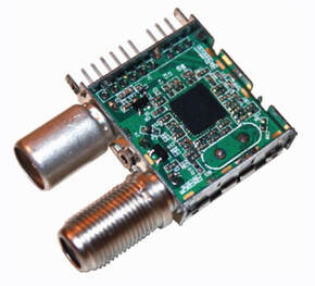
The NXP OM3948C reference design of a TDA18250 cable tuner. It measures 24x28mm. [NXP TDA18250 Cable Silicon Tuner leaflet, 2011]
|
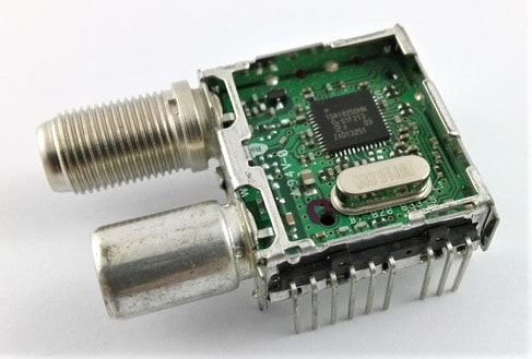
The Nutune FC2223 cable tuner module based on the NXP TDA18250 SiTuner. Dimensions are 24x28mm. Apart from the swapped A- and B-side assembly it is identical to the OM3948.
|
Development, in the meantime, threw overboard all reservations as to silicon tuners, and finally started making products based on the second generation NXP SiTuners TDA18250 for cable and TDA18272 for terrestrial hybrid reception. This allowed much smaller tuner modules, although it is not clear how much performance specifications had to be compromised. In any case, the modules were now really small, the FC2200 and FJ2200 tuners measured 24 by 28mm, and only contained the SiTuner HVQFN package plus a 16MHz crystal plus some biasing and decoupling external components. It is interesting to note that the final Nutune FC2200 product is almost identical to the TDA18250 reference design by the BL TV Frontend of NXP.
|
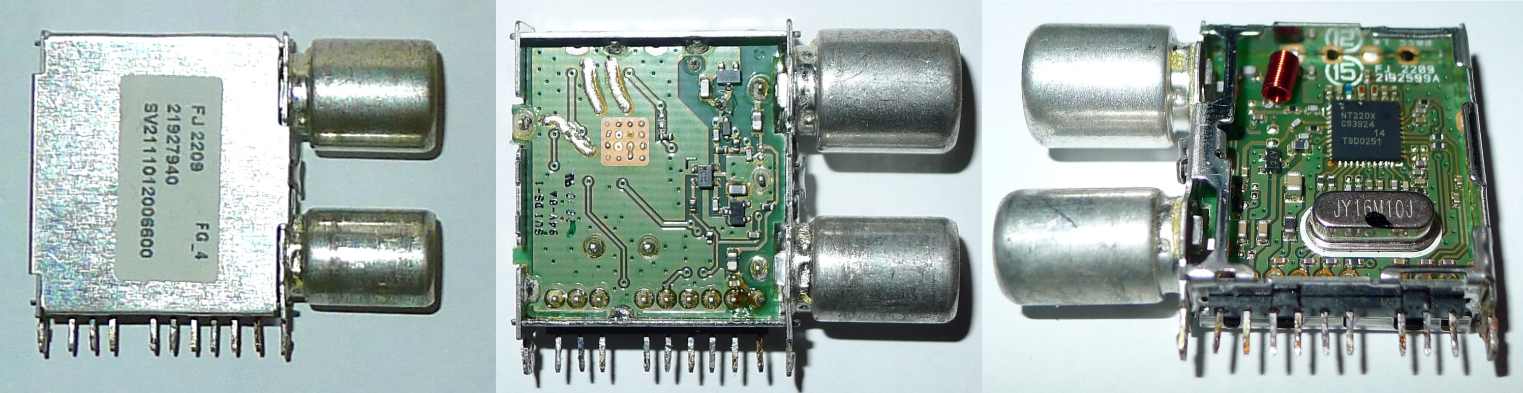
Three pictures of the Nutune FJ2209 tuner. This sample was used in the Humax IR Fox-Z STB. The IC used is coded NT2203, and was probably the re-coded TDA18272. [Maarten Bakker]
|
Similarly, Nutune developed the FJ2221 quad cable tuner, based on the TDA18260 dual cable silicon tuner IC, of which it contained two. Because of the 1,6W IC power consumption, so 3,2W in total, additional measures were required to transfer the heat away from the ICs. The top cover was consequently bent inwards and pressed against the IC upper surface, for optimum heat transfer to the metal frame. The final Nutune family was the FK1600 terrestial tuner, based on the latest TDA18273 fourth generation Silicon Tuner from Caen. For the first time ever a joint press announcement was made, with Nutune's marketing manager Lim Kui Yong explaining that SiTuners were OK, but that TV customers wanted them in a can, and NXP BL TV Frontend manager Olivier Harquin explaining that can tuners were on the path to tuners-on-the-board. The FK1600 was the smallest tuner ever designed by the Philips-NXP-Nutune lines of business: 24 by 20mm. Of interest is that the TDA18273 was marked as NT2203, blocking fast copying of the design.
|
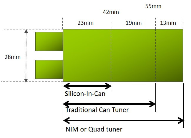
The new Nutune module mechanical dimensions and partitioning, used from 2009 in the FC2200 and FJ2200 families.
|
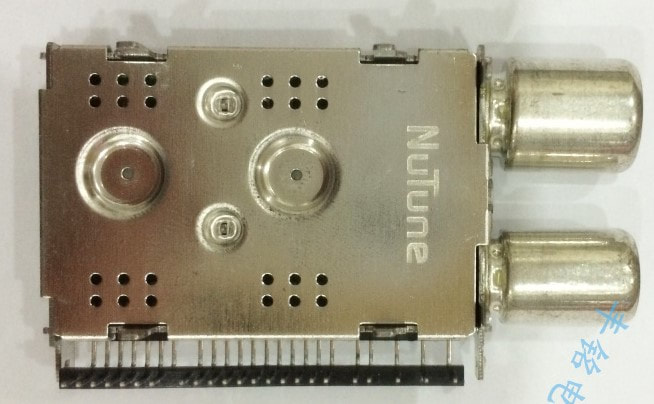
The Nutune FJ2221 quad cable tuner, using two TDA18260 dual tuner ICs. The frame depressions are for heat transfer. Size of the module is 55x28mm.
|
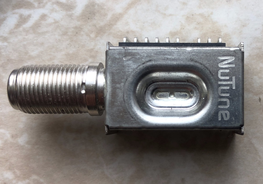
The Nutune FK1603 terrestrial tuner based ont he TDA18273 SiTuner IC. The depressed top cover is for heat transfer. [Detlef Marbach collection]
|
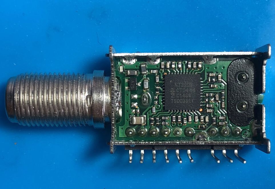
Interior view of the Nutune FK1603 tuner. Note that the IC is marked as NT2203 to conceal which IC it is. Size of the module is 24 by 20mm. [Detlef Marbach collection]
|
But .. why is the FK1600 the last Nutune product? To put it simply, Nutune business was dramatically bad, and collapsing at an unprecedented speed. In 2007, when discussions around the Nutune JV started, the combined sales of NXP RF Solutions and Thomson tuner business were around 240-250Mio$. As already mentioned, the total sales in 2008 declined to 187Mio$, and continued to a dramatic 112Mio$ in 2009. It then stabilised somehow in 2010, barely reaching 100Mio$. Where 2008 still showed a meagre profit, 2009 saw the first time structural loss of the tuner business (7,5Mio$) which became much bigger in the following year. This resulted in the obvious restructuring measures, which meant that Villingen, the former Thomson development site in southern Germany, was closed October 2010. To be fair, non of the multi-tuner modules Villingen had been working on since 2008 had made it to production. This left only Singapore development with only thirteen engineers, not a team size allowing a wide portfolio of products. Most activities thus reduced to industrializing the reference designs provided by the application support team of the BL TV Frontend, mainly the FC2200 and FJ2200 products described above that were launched from end 2009 and throughout 2010, and the FK1600 as the last one in 2010.
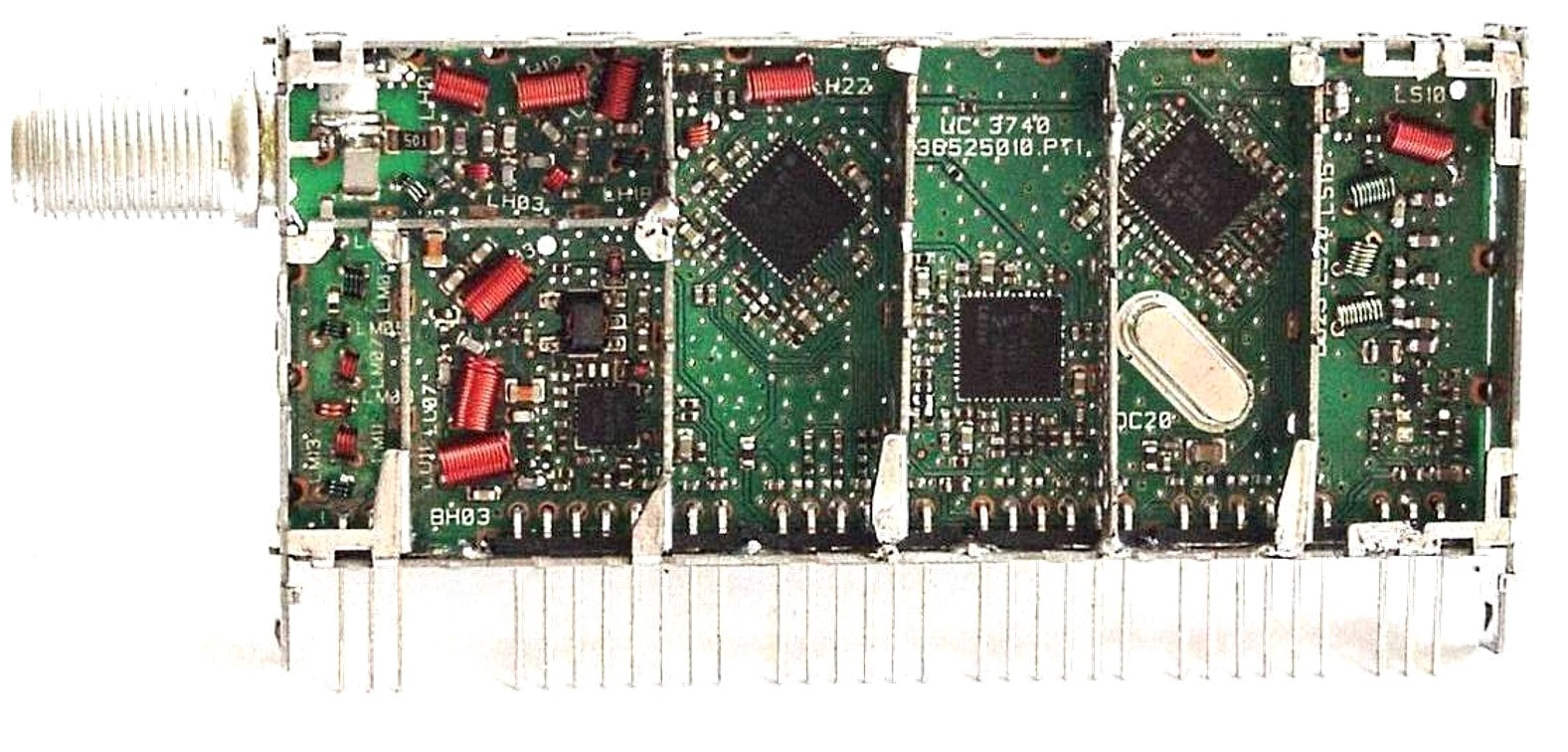
One of the ambitious Nutune products that never made it beyond the prototype stage: an input triplexer (RF in, upstream below 41MHz and MOCA upstream above 1112MHz), followed by three Si Tuners: one TDA18253 master tuner, two TDA18252 slave tuners.
|
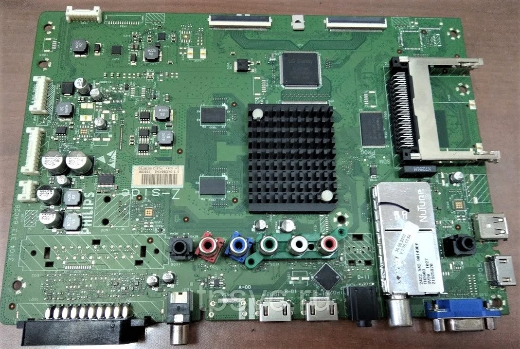
The very last Philips/NXP/Nutune line of tuners in a Philips chassis: this is the TH2307 hybrid DVB-T/QAM/analogue tuner on 40PLL5404 of the Q555.2 chassis, which caused serious field quality problems. [Fpsvc.ru]
|
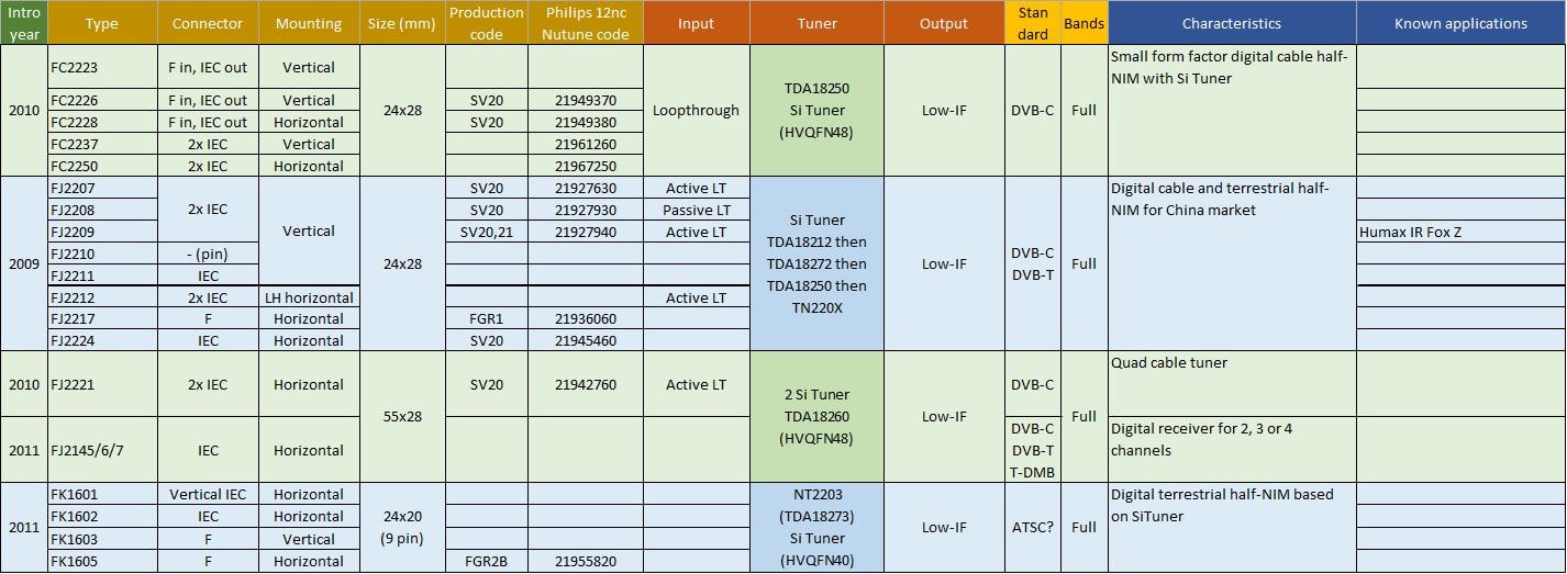
The last families of products developed by Nutune, all based on the NXP SiTuner ICs.
As mentioned, one of the primary requests to Mark Foley was to assess the future of Nutune. He quickly advised the NXP management that he saw no serious future for the JV because the problems were structural: too high fixed costs that would require serious financial provisions to restructure, declining sales and declining margins. NXP now wanted to get rid of the JV as fast as possible, and during the second half of 2010 a deal was made with the US company American Industrial Acquisition Corporation (AIAC), a New York-based private equity company that claims to specialize in buying loss-making industrial activities from large companies and bring them back to profit. Nutune was sold to AIAC December 2010 for one Euro, including all its liabilities and debts. At the moment of the transfer Nutune still employed 2800 people in its Batam fabs and around 150 indirects, now only in Singapore and Batam because, as already mentioned, the Villingen organisation was closed in October. Mark Foley left March 2011 after finishing his 2-year contract, and was replaced by Peter Graham, the young son of one of the AIAC founders/directors. Because AIAC is an American company, a legal council was assigned that followed Graham everywhere and turned all discussions into legal contracts.
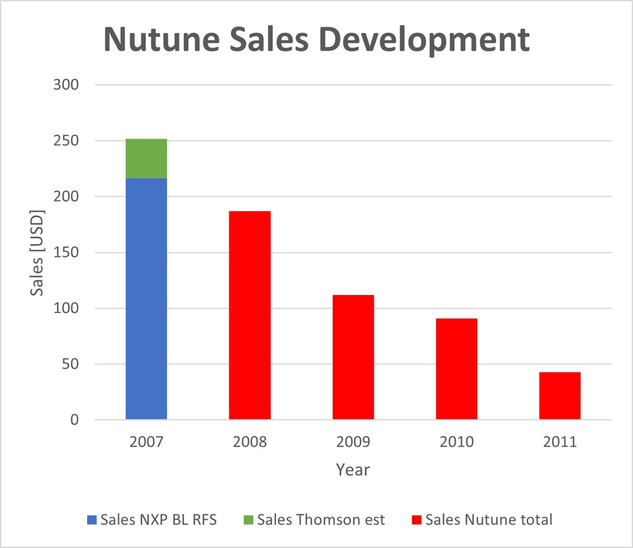
The dramatic sales decline of Nutune, that started right after it was created September 1st, 2008.
|
Again, the new AIAC owners started off on a bad footing: a major quality issue with Philips TV developed. In 2011 Philips reported unacceptable returns of its top line European Q551 and Q552 TVs in the field, due to catastrophic failure of the tuners. These were the Nutune TH2603 and TH2627 hybrid tuners, of which half a million were used between November 2010 and January 2011. The problems were due to failing electrolytic capacitors and probably developed very soon after the sale of the sets. Philips claimed that 12,300 of the tuners had already failed or were expected to fail soon, a field call rate of 2% within a year, which is indeed a dramatic performance for a high end chassis like the Q552. The new Nutune CEO now made a dramatic move by re-calling all tuners in the logistic pipeline to Philips, including a few 100.000 consignment stock. In total some 800.000 tuners were re-called. This in turn created the fear within Philips that a major issue was at hand, and they decided to switch supplier immediately: a Sony SiTuner in a can. Philips claimed retribution for the repair cost, a modest 3Mio$, and threatened Nutune with a lawsuit.
|
|
Under the AIAC management the company now came in a negative spiral. Turnover in 2011 reduced by 53% compared to 2010, reaching an all-time low of just 43Mio$. The rapidly declining sales caused the Batam fabs to become underloaded, leading to heavy losses. But AIAC was unable to raise or borrow money because of the Philips lawsuit hanging over its head. Customers cancelled orders, while suppliers only wanted to deliver goods based on "cash-at-delivery", which was not possible. August 2011 a next wave or restructuring started, but the company was unable to pay the legal retrenchment benefits to its former employees, instead proposing a spread 12-month payment. In October the AIAC lawyer, now also sales director, wrote a letter to all customers that production would be discontinued and urgently advised all customers to find alternative sources for their Nutune products. In November payments to the entrenched employees stopped altogether, leading to a further lawsuit by the Singapore labour unions February 2012. That same month AIAC decided to close the Batam fab, but the factory employees went on strike and blocked the shipment of equipment to Penang. In March the Batam plant was closed. With the Philips court case in July hanging over its head, sales collapsed to zero, and debts higher than the total asset value, AIAC filed for Chapter 11 protection of its Nutune subsidiary July 2012. For half a year it then tried to find back customers, get supplier agreements, and sell off assets, with overall limited success. January 2013 Nutune was declared bankrupt. A very, very sad and embarrassing end to the once great Philips tuner business!
|

February 2012 employees of the AIAC-Nutune Batam fab went on strike, to protest against the impending closure.
|
Philips TV sold to TPV, 2012-2014
By 2008 the former Philips Consumer Electronics, recently renamed to Philips Consumer Lifestyle, had already dramatically reduced its television activities, now under the BG Connected Displays. In the US all Philips and Magnavox sets were developed and produced by Funai, from Japan, while the non-US low and mid end LCD chassis were now developed and produced by TPV, from China. Internal development was henceforward limited to the single high-end platforms from Brugge, Belgium, with the remains of the TV-lab in Eindhoven for pre-development. Singapore TV development and production had been closed, while all PCB manufacturing and stuffing had been outsourced and sold to the US company Jabil in 2002, which also took over the Kwidzyn (Poland) CRT-TV assembly plant in 2005. Philips nevertheless still operated a global TV manufacturing operation with assembly factories in Székesfehérvár (Hungary), Suzhou (China), Manaus (Brazil), Ushuaia (Argentina), Ciudad Juarez (Mexico) and Pune (India). The old fabs in Dreux (France) and Brugge (Belgium) were closed in 2009.
|
The real problem of Philips TV was the declining market share! From the very early days in the 1950-ies it was known to all players in the field that television was a volume game: only increasing volumes could generate the cash required for new investments in chassis, technologies and factories. Until the 1980s Philips was one of the champions of that game, step by step growing both organically and by sweeping up competitors, mostly in Europe and the US but also in Australia, New Zealand and other countries. This strategy led to a solid global top3 position in TV, together with the Japanese giants Sony and Matsushita (Panasonic, JVC). For the next ten years until around the year 2000 this ranking remained more or less stable, until the Korean players Samsung and LG challenged the hierarchy and took over leadership with the switch to LCD TV in the years following. Although Philips was able to grow its top line to 6,5Bio€ TV sales in 2006, volumes did not increase from the 17Mio sets already achieved in 2000, which had a single consequence: their absolute market share almost halved!
|
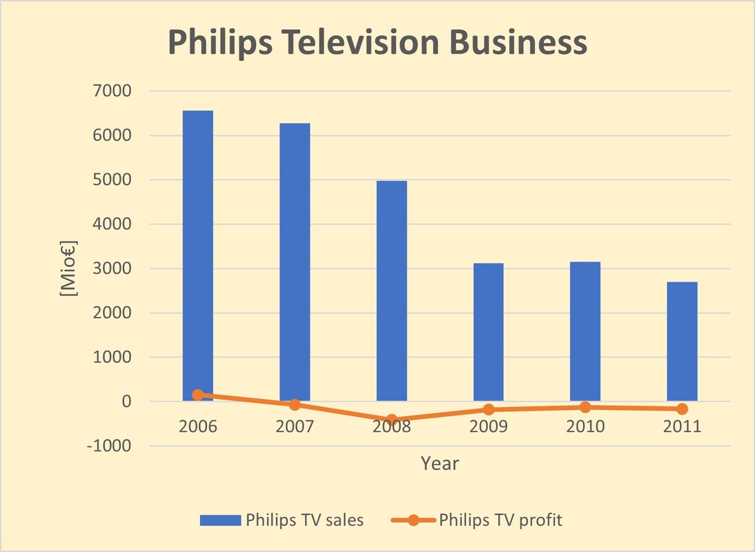
Sales and profit over the last 6 years of the Philips TV business. [Philips Annual Reports 2006-2011]
|
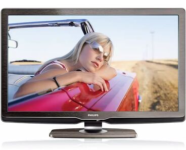
The 2009 Philips flagship TV: the Q549-2 chassis 37PFL9604 for 1080i full-HD and with the new segmented Ambilight2. [Philips]
|
Although the TV business still made a marginal 2,5% profit in 2006, this was insufficient to fund the CRT-to-LCD, standard-to-high definition and analogue-to-digital switch-overs, all happening more or less at the same time. When the company then started to sell off its most loss-making low-end business to Funai and TPV a negative spiral started of declining sales and increasing losses, which forced Philips to focus more and more on the single remaining high-end LCD segment with its Q-platforms. Continuous cost reductions kept the losses to 1-2%, but sales collapsed to below 3Bio€. Obviously, the point-of-no-return had been passed a few years earlier, and the Philips management, now under van Houten and still focussed on healthcare only, wanted to get rid of this risky business. April 2011 a joint venture with TPV Technologies was announced.
|
The history of TPV goes back to the small US TV maker Admiral, which started a subsidiary in Taiwan in 1967 called Admiral Overseas Corporation (AOC) to produce colour TV sets. In 1990 AOC started activities in China but was required to form a JV with a local company which became Top Victory Electronics Ltd or TPV. Although AOC survived as an independent TV brand, the main activity of TPV became ODM manufacturing for other companies, especially Philips. Step by step the co-operation with Philips was intensified:
- in 2005 it took over the low-end LCD PC monitors and low-end LCD TV development and production from Philips in Taiwan.
- in 2008 it obtained a global marketing license for Philips TVs, with the exception of Canada, US and Mexico that were covered by Funai.
- in 2009 it took over all remaining LCD monitor and hotel TV business from Philips.
|
The last step was announced in April 2011: Philips would bring all its remaining TV business in a JV with TPV that would be called TP Vision, TPV obtaining 70% of the shares and Philips the remaining 30%. The deal included all remaining Philips TV factories (Brugge, Székesfehérvár, Suzhou, Manaus and Ushuaia; Pune had been sold in 2010 and Juarez was part of the deal with Funai). Closing the deal took a full year, due to delays in obtaining governmental permission from China but was finally achieved April 1st, 2012. All remaining 3.300 employees of the Philips TV business moved to TP Vision. As part of the deal TPV and Philips committed to invest pro rata 170Mio€ and provide 100Mio€ invester loans. TPV would start paying, after the 2nd year, 50Mio€ or 2,2% of its turnover, whichever was larger, to Philips in return for being allowed to use the Philips brand name.
Immediately after the deal was closed both Philips and TPV started rationalizing their organisations. Although TPV could reduce cost by using its Chinese component supply chain and could increase the load of some of the fabs with its own AOC and Envision brands, further cost measures were deemed necessary. This involved quite some former Philips activities:
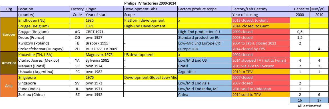
Summary of the Philips TV development and production sites from 2000 to 2014. None survived within Philips.
|
The new TP Vision logo.
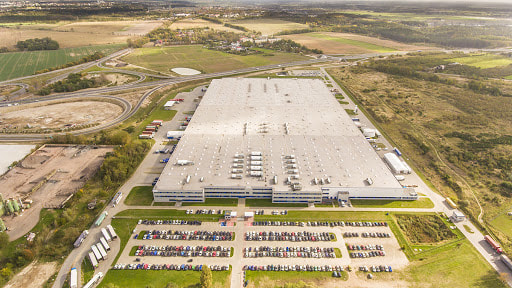
The enormous TP Vision TV factory in Gorzow Wielkopolski, where all
European Philips branded TVs are produced.
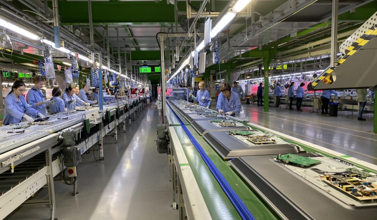
Production line in the TP Vision Gorzow fab. During most of the production flow LCD TVs are laying flay on the conveyor belts. [Fwd.nl]
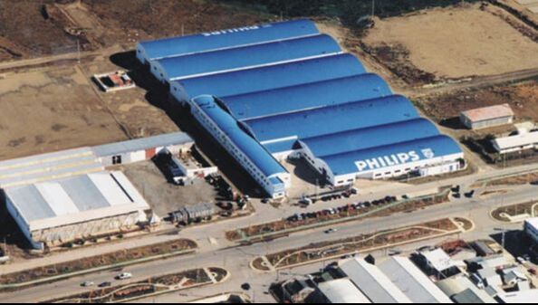
The former Philips CE fab (they produced more than TVs), now TP Vision Ushaia fab in Terra del Fuego, at the southernmost tip of Argentina.
|
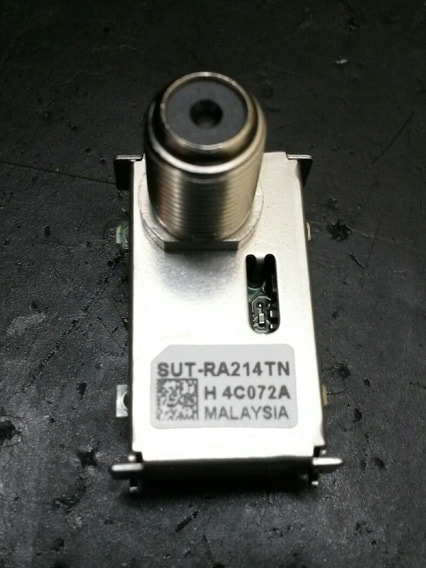
The Sony SUT-RA214 Si Tuner module that replaced all Nutune tuners from 2011 onwards.
|
What was the effect of all this on the TV chassis? When the Philips-TPV JV discussions started, the TV550 platform with the Q55x chassis was in full production since 2011, finally based on the PNX85500 TV core of the former NXP BU Home, which had now become Trident. As discussed, some of the models experienced serious customer field problems and returns due to defective Nutune tuners. The bad response of Nutune and the ensuing court cases made that Philips completely dumped Nutune, and made running changes to a competitor, which turned out to be the relative newcomer Sony. A few years earlier Sony, in the slipstream of Philips Semiconductors/NXP had started development of Silicon Tuners too, but also of the associated tuner modules! So where NXP TV Frontend and RF Solutions had effectively refused to work together on joint SiTuners-in-a-can, Sony simply did it. The Nutune modules were thus replaced by the Sony SUT-RA214, a module similar to the last Nutune FK1600. The sad conclusion is thus that the Si Tuner, a development started 10 years earlier in the NatLab, succesfully transferred to the Product Division, and with Philips/NXP the global market leader, were only used in Philips TVs when Philips TV was sold, the module maker bankrupt and the IC supplier - as we will see -at the point of stopping development. Whatever the root cause, it does not sound as a story where Philips maximized the use of its internal technologies!
|
Unfortunately the story is not over yet, one more step to go. In 2012, the year TP Vision was created, the Fusion platform was launched, based on the now Trident Fusion 240 IC in 45nm CMOS. This was a state of the art TV, supporting screen sizes up to 60", full-HD, fantastic contrast, and colour quality, 2D Ambilight and even 3D picture processing. It was also the first Philips Smart-TV with WiFi. However, whether it was a former Philips design weakness, or a cost saving imposed by the new TP Vision management, but the heat sink of the Fusion 240 SoC was much too small and badly mounted. The SoC generated so much heat that the thermal glue of the IC heat sink let loose, the heat sink came off, without proper cooling the IC overheated and the solder ball grids connecting it to the PCB melted away. This gave many field returns, again, requiring "re-balling" and re-mounting of the IC and placement of a new, bigger heatsink. Like the quality issues with the Nutune tuner one chassis earlier, this incident marked the end of Trident as a supplier, which went bankrupt. For a while one can find the Fusion IC marked as Sigma, which took over the Trident TV business, but from the next QM14 chassis in 2014 TP Vision switched completely to MediaTek. Which marks the end of Philips Semiconductors/NXP presence in Philips branded TV sets. From now on there was really no single link between Philips branded TV sets and the former company. After 78 years - if we take 1936 as the starting point - Philips was no longer involved with TV. As if to formalise this, in 2014 Philips sold its last 30% share in TP Vision to TPV.
It is fair to say that TPV (or TP Vision, but they are now the same) has been very successful with selling the Philips-branded TVs. Although apart from the name there is no longer any link with the former Philips activities, the Philips brand image in TV is still rock solid, and although Samsung and LG have become the market leaders, Philips is still a very strong Top3-5 brand, at least in Europe. This is supported by the doubling of production capacity in the TP Vision Gorzow fab to 8Mio sets per year, a volume no Philips TV fab ever produced. The question that comes to mind is obviously: why does TPV succeed where Philips failed?
It is fair to say that TPV (or TP Vision, but they are now the same) has been very successful with selling the Philips-branded TVs. Although apart from the name there is no longer any link with the former Philips activities, the Philips brand image in TV is still rock solid, and although Samsung and LG have become the market leaders, Philips is still a very strong Top3-5 brand, at least in Europe. This is supported by the doubling of production capacity in the TP Vision Gorzow fab to 8Mio sets per year, a volume no Philips TV fab ever produced. The question that comes to mind is obviously: why does TPV succeed where Philips failed?
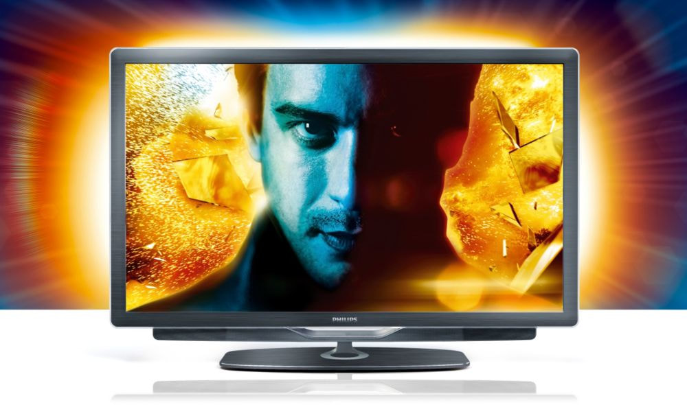
The last TV platform fully developed and produced by Philips: the TV550. This is the 2010 Q551 47PFL9705 with Ambilight. [Philips]
|
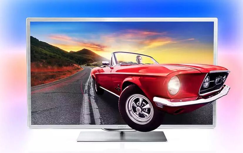
The last TV platform developed by Philips, but already produced under TP Vision: The Fusion. This is the 2012 QFU1.1 chassis, model 60PFL9607 3D Smart-TV. [Philips]
|
To finish the story, the next step was to get rid of the remaining parts of Consumer Lifestyle, mainly audio and connected entertainment. The intention was that Funai would take this over, continuing on the path started with VCR and Magnavox TV. Although the two companies signed a Letter of Intent January 2013, they could not come to a final agreement in the months following, and in October Philips announced that it stopped the negotiations and would sue Funai for breach of contract. Apparently one of the main issues was the destiny of the TV factory in Ciudad Juarez, Mexico, which Funai refused to take over. Following this set-back Philips put all remaining Consumer Lifestyle activities in a new subsidiary called Woox Innovations, based in Hong-Kong, while the Juarez fab stopped TV production and switched to other products. April 2014 it was announced that Woox was taken over by the US company Gibson, famous (only) for its electric guitars. It turned out to be another doomed spin-out of Philips. To be sure everybody understood, Philips closed the whole process of killing its once dominant Consumer Electronics business by changing the company name from Royal Philips Electronics to Royal Philips. The end of an era.
TDA18273 to FST, the last silicon tuners, 2011-2014
By 2010 the BL TV Frontend, the only remaining tuner-related activity within Philips and NXP, was at a critical point:
- they were the only remaining business from the once large Semiconductors Consumer activity but had safely landed within the analogue/RF focussed and largest Business Unit of NXP, the BU HPMS.
- at the same time sales were rapidly decreasing, primarily due to the declining IF sales, where product development had stopped and IF functions in TV were increasingly digitized and integrated. From the all-time high of 195MioUSD RF/IF business in 2008 comparable sales had declined to 144MioUSD in 2010.
- where the Si Tuner finally started to run at high volumes, especially in the cable domain, but with the ever associated price reduction. The market price of a Si Tuner was now at 0,80-1,00USD and declining.
- the BL was losing Broadcom as a major cable Si Tuner customer. The 2010 BCM3422 had been the last proprietary Broadcom marked tuner IC, and from 2011 sales were halved every year from the original 35-40MioUSD/year.
- all forecasts predicted that 2011 would be the turning point of SiTuners in TV, a segment that until now had refused to use the SiTuner. All off-air SiTuner sales, not more than 18MioUSD in 2010, were in the STB, PC and DVD-Recordable domains. However, the main technical challenge was that, despite the claims of the BL, the latest TDA18272 was not deemed fit for off-air reception, at least as a stand-alone device and compared to a traditional can tuner.
|
The most important project of the BL TV Frontend thus became the TDA18273, the next generation off-air SiTuner. The architecture was almost identical to the TDA18271 and 18272, with an additional HPF/LPF band splitting filter after the LNA. Most other improvements came from individual IP block modifications. These centred around the N+/-1 adjacent channel performance and especially the AGC. As already shown when introducing the previous generation, the AGC sub-system had grown to become very complex, with five different gain controlling stages. Take-over points of the different control loops was an important system optimization element, that was further optimized in the 18273. Another element was that the European Nordic digital TV requirement demanded a 20dB larger gain control range, which was in the previous 18272 only possible by involving the channel decoder.
|
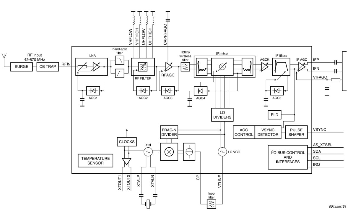
Block diagram of the NXP TDA18273 off-air SiTuner. [NXP TDA18273 Data Sheet, August 2010]
|
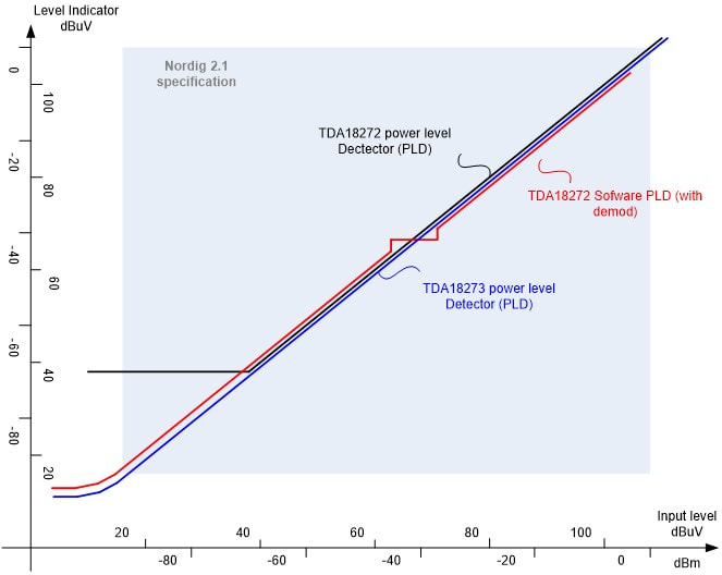
The improved gain adjustment range of the previous generation TDA18272 and new TDA18273.
|
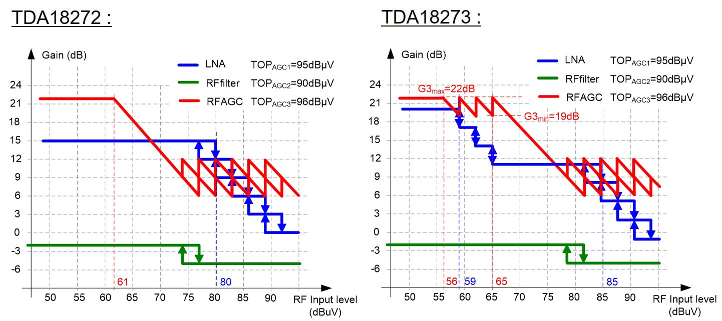
The implemented modifications of the different internal AGC TOP and control schemes of the TDA18272 and 18273.
|
The TDA18273 was introduced in 2011, followed by the 18214 cable versions and in 2012 the TDA18274 that integrated the RF filters in the same type of laminate package as the earlier TDA18271. In parallel the MOPLL sales were rapidly dropping due to a market-wide End-of-Life announcement by both NXP and Infineon (only TI would continue and in the end license the design to a Chinese player). Although in 2010 the BL still sold 50Mio MOPLL ICs, at an average sales price of 0,20-0,25USD this was barely 11MioUSD. The HS5 bipolar technology that was used for all MOPLLs except the TDA6650 was taken out of production at the end of 2011. This caused a serious drop in the BLs market share in TV, declining from 50 to 35%. The real problem of the BL, however, was not the fierce competition in the market but the internal NXP management. In the 2010 and 2011 strategic reviews it became clear that it would be very difficult to maintain growth or even stay flat in sales in the coming years. In a market of 250Mio TV tuners and 50Mio STB off-air tuners, even at a 35% market share, with an ASP of 0,50USD sales would not be more than 50MioUSD. Even adding the 40MioUSD cable sales, which was a growing market mainly due to the increasing number of tuners per STB, the BL would not be bigger than 100MioUSD. There were growth opportunities, for example wide-band receivers for cable or satellite STB, but these all required advanced CMOS technology with the associated high development costs. The NXP management therefore concluded that the SiTuner business was a dead-end activity, R&D was substantially reduced to a maintenance level and profit had to be pumped up to 25%.
|
The single new development that continued was the TDA18265 Full Spectrum Tuner (FST) for cable STB. The DOCSIS3 standard allowed channel bundling, i.e. spreading high bandwidth data over multiple RF channels to allow very high cable transmission speeds. Since the bundling could include as much as 24 channels, it became much more efficient to make a single wideband receiver than having 24 single tuners in parallel. The core of the IC was a 2,8GHz 13-bit ADC that digitized the 42-1002MHz RF input band, which was pre-filtered, and gain controlled by a separate QuBIC4 IC, the TDA18204. The 18265, which was designed in TSMC 65nm CMOS, also contained the return channel modulator and DAC. The FST ICs were sampled in 2013.
Based on the NXP MT verdict that the tuner IC business was no longer of interest, efforts were made to sell the BL (project Tango) but no buyer was found. This led to the next round of restructuring, where all developments not deemed to contribute to the profit were stopped. The name was changed to BL RF Transceivers, a new and reduced management installed, and early 2013 the total employee size cut by halve. Although the SiTuner sales were quite successful in terms of volume (160Mio TV and STB SiTuner ICs in 2012, amounting to a roughly 35% market share), the price per IC had come down to 0,50USD and continued to decline to 0,35USD in the following years. In other words, the volume growth could not compensate for the price erosion, and net sales diminished. |
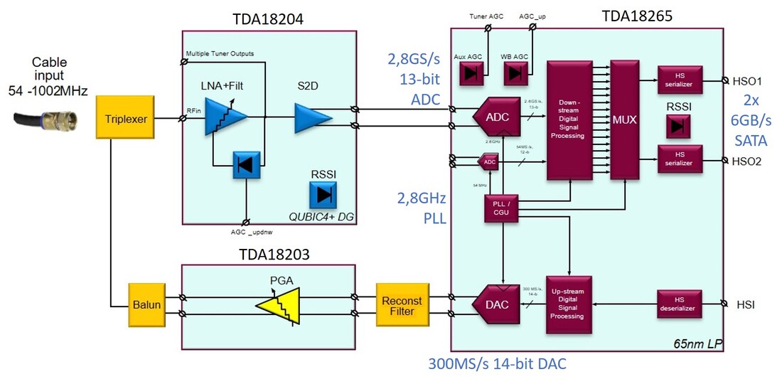
Block diagram of the NXP Full spectrum Tuner for cable STB, with the core TDA18265 digital IC.
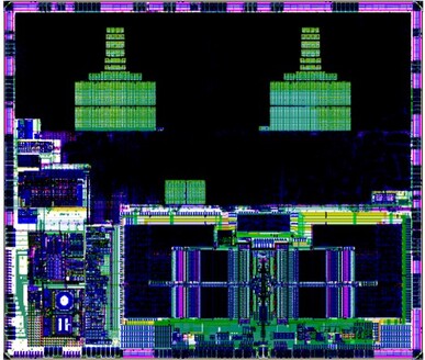
Layout of the TDA18280, the last Full Spectrum Transceiver that was in development when all activities stopped. It was a 28mm2 IC in 65nm CMOS, for 8-channel bonding, including the QAM demodulator and Out-of-Band receiver. The design team achieved a first-time right design early 2014.
|
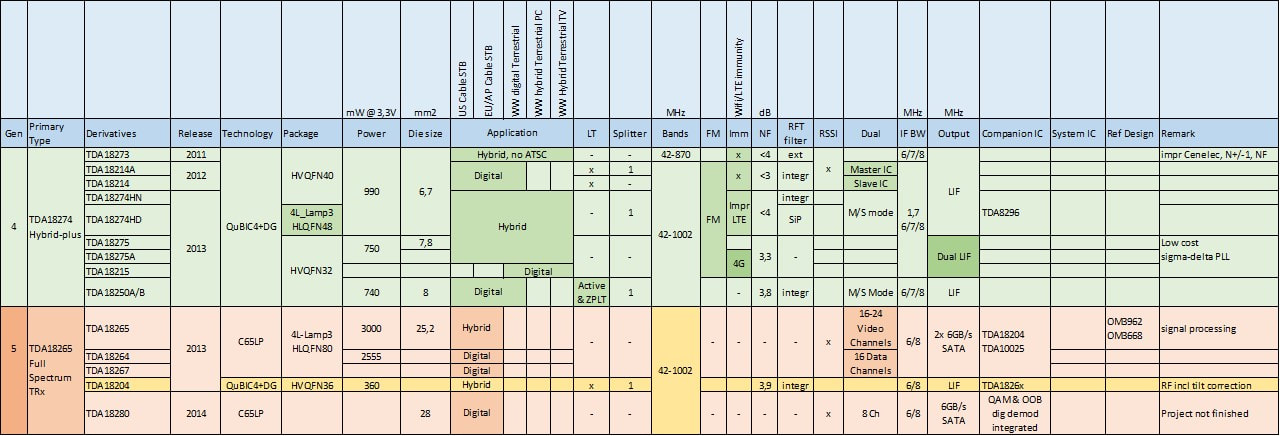
Overview of the last generations NXP Si Tuners TDA18273 to 18275, and the Full Spectrum Transceivers.
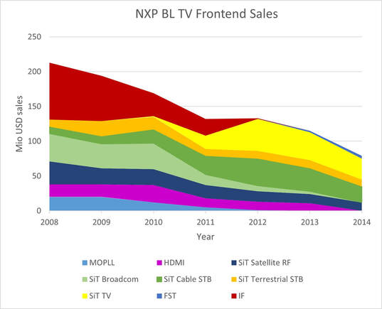
Sales development of the NXP BL TV Frontends in the last years of its existence.
|
By the end of 2013 NXP threw in the towel, all SiTuner activities were stopped, the Business Line became a Product Line under the BL Emerging Business and changed the scope to Zigbee and Bluetooth wireless transceivers. The FST activities were sold to ST and continued for a while as sub-contracted design service for ST. This brought an end to the Philips Semiconductors/NXP TV tuner IC activity, which had been the global market leader in this segment almost from the beginning with the first pre-scaler ICs in 1978. Although this leadership was based on the continued functional integration (pre-scaler to PLL, MO, MOPLL and finally the SiTuner), this integration and the associated price erosion also led to the end of the activity: even at 25% market share in a 300Mio units market the 0,3USD price of a SiTuner made it an unattractive segment. And so, the last tuner-related activity came to an end.
|
|
|
At this point one would conclude that everything related to the former Tuner and Tuner IC activities of Philips/NXP/Nutune had completely disappeared. But was this really true? No! Like the village of Asterix resisting the Roman empire, one very small activity resisted total annihilation. Once Nutune filed for chapter 11 July 2011 Lim Kui Yong, one of the former Nutune managers was called back by the curators to take the position of COO and help sell off the remains of Nutune. He had been the Singapore R&D manager at the end of RF Solutions and been leading Sales & Marketing under Nutune until it AIAC took over. In the following months this resulted in incidental manufacturing of small batches of products for desperate customers with no alternative to the Nutune product; to selling off component stock (mostly to competitors) and to selling of production equipment (mainly the FCM SMD onsertion lines). In parallel he founded the company RF Point, like Nutune based in Singapore, and obtained agreements from AIAC/Nutune for use of the Nutune IP. With NXP and TI deals were made for the continued supply of the critical and in many cases Nutune-proprietary MOPLL (TI) and SiTuner (NXP) ICs. Based on these agreements RF Point continued production of a small number of Nutune products, but now with manufacturing 100% outsourced to Chinese sub-contractors. To highlight the continuity the products continued to use the Nutune type numbers but now labeled under the brand name Global Tune Technology (GTT).
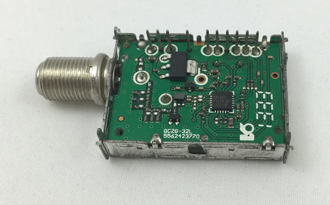
The RF Point FC1228, a former Thomson/Nutune cable tuner based on a MaxLinear SiTuner. [All pictures RF Point web site]
|
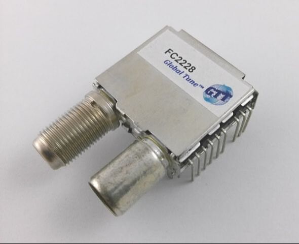
The RF Point FC2228 cable tuner based on the NXP TDA18250 SiTuner and a 1:1 continuation of the Nutune product.
|
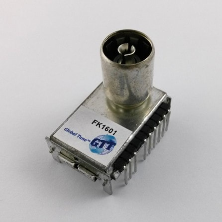
The RF Point FK1601 terrestrial tuner, based on the NT2203/TDA18273 NXP SiTuner.
|
With the same approach products were made based on MaxLinear SiTuners for terrestrial applications, NXP SiTuners for cable applications and RDA ZIF SiTuners for digital satellite. RF Point remained a very small 4-person company, and obviously could not achieve volumes and portfolio diversity of Nutune, let alone Philips/NXP. Still they were able to sell and produce in total 60Mio tuner modules from 2012 to 2018. By that time most of the MOPLL and SiTuner components had reached end-of-life. NXP had stopped SiTuner production completely after the Freescale merger in 2015, TI did the same and recently also MaxLinear stopped SiTuner production. The price of a SiTuner had dropped to around 0,15USD, while the tuner module market price had come down to 0,50-0,60USD. Even RF Point tuner volumes have reduced to a few 100.000 per year only, and the company now focusses on selling RF-ICs. But it bravely extended the Philips/NXP/Nutune tuner heritage by another ten years!
Summary
Before turning to the organizational analysis, let us first have a last look at the product development over the last 15 years. To start with television, still the main application. The core of the TV tuner line remained the UV1300 WSP tuner, going through another 4 generations from 1998 to 2007. After the problematic Mk1, the Mk2 re-introduced a stable technology platform, while the Mk3 introduced new features in the form of Wideband AGC, optional FM radio reception, optional LNA and optional splitter-loopthrough. There was even the UV1318 high performance tuner for Philips high-end TV. But that was the last time, the Mk4 was just brute force cost down using a single-sided PCB and the last Mk5 mainly a new mechanical version with the vertical connector. It is interesting to note that, because the UV1300-Mk4 no longer contained the UR1300 FM-radio version, the UR1300-Mk3, quite popular in the low-end segment, lived for almost eight years. In the meantime the switch-over to digital TV standards took place, intially with the digital TD1300 on so-called Digital Bolt-on boards, but with the Jaguar platform a normal option on the main small signal chassis. With the Q52o from 2007 the digital tuner became the standard module, with UV1300 analogue tuners for cheaper non-digital TVs. They finally merged into the HD1800 hybrid tuner, which was (finally) a universal tuner that could receive all standards by violating the classical IF defintions and applying the same IF filter around the digital 36,15MHz to all of them.
Overall, in the twlve years from 1998 to 2008, five generations of tuners were deployed, an average of two years with a noticeable acceleration towards the end. In this same period the sales price of a standard tuner reduced from 4 to 1,5USD, further declining to 1USD in the Nutune years due to the introduction of the SiTuner module. As the below graphical overview shows, the real problem of the RF Solutions tuner business was not they were not used by Philips TV, on the contrary, but that the number of chassis developed by Philips reduced to one high-end platform, with limited volumes.
Overall, in the twlve years from 1998 to 2008, five generations of tuners were deployed, an average of two years with a noticeable acceleration towards the end. In this same period the sales price of a standard tuner reduced from 4 to 1,5USD, further declining to 1USD in the Nutune years due to the introduction of the SiTuner module. As the below graphical overview shows, the real problem of the RF Solutions tuner business was not they were not used by Philips TV, on the contrary, but that the number of chassis developed by Philips reduced to one high-end platform, with limited volumes.
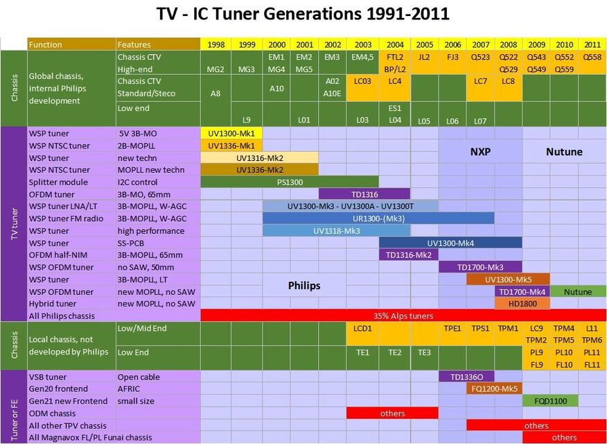
Overview of the Philips and NXP tuner modules used in Philips TV chassis. These chassis are indicated in the green rows, where orange field indicate flat TV (initially some plasma screens, mostly LCD).
The non-TV applications show the same analogue-to-digital standards conversion as TV, although the actual conversion was different per application. In the PC MultiMedia frontends the conversion was managed from 2004 by having parallel purely analogue FQ1200 and hybrid FMD or FQD1200 modules, with the additional DVB-T or ATSC SAW filter output. After the last FQ1200-Mk5 the hybrid versions were the only ones remaining. Interestingly, the PC MM market for TV frontends had essentially disappeared around 2007, when streaming took off. But the (hybrid) frontend had a second life in the LCD TV market. As moted earlier, where Philips TV had mostly opposed the use of frontends (claiming they did the IF better themselves), once the development was taken over by TPV frontends all of a sudden appeared in Philips TVs.
As can be seen from below overview the cable STB market went very smoothly, being digitally almost from the beginning of the century. Successive CD1300 generations followed every two years, mostly alternating between smaller module size and key component improvements. The parallel CU1200 NIM proved a very successful and profitable segment.
The terrestrial digital tuners, serving both TV and the STB, saw a more hectic succession of products. Digital terrestrial started later than cable, but once it did developments went fast and generations followed each other every year. But for RF Solutions the conversion was very successful, with the digital tuner being the biggest volume when the conversion was completed. Also here the TU1200 NIM was an important product to complete the portfolio, not in volumes but in margin and to cover the full market.
Satellite, as had been explained multiple times, was the segment were full integration came first, including eventually tuner-on-the-board solutions. The SDM1800 in 2003 therefore was the last satellite frontend module, after the first SF900 in 1991. Although the SU1200 NIM remained a nice solution for demanding customers, it was too expensive for this segment. So, around 2004 the satellite segment had stopped as the first diversification path of Tuners/RF Solutions.
The segment that was supposed to take over, mobile and portable applications, was no success. The market for portable (digital) TV reception had always been small and remained so. DVB-H/ISDB-T TV-on-Mobile also failed because it was taken over by cellular 3G and 4G video streaming. Wifi modules potentially were an interesting domain, but all initiatives in this direction were killed by NXP cost cutting management.
The dramatic and ultimately devastating effect of all these developments was that by 2008, when RF Solutions became Nutune, the product portfolio had reduced to almost exclusively digital cable and digital terrestrial tuners. None of the diversification segments had survived!
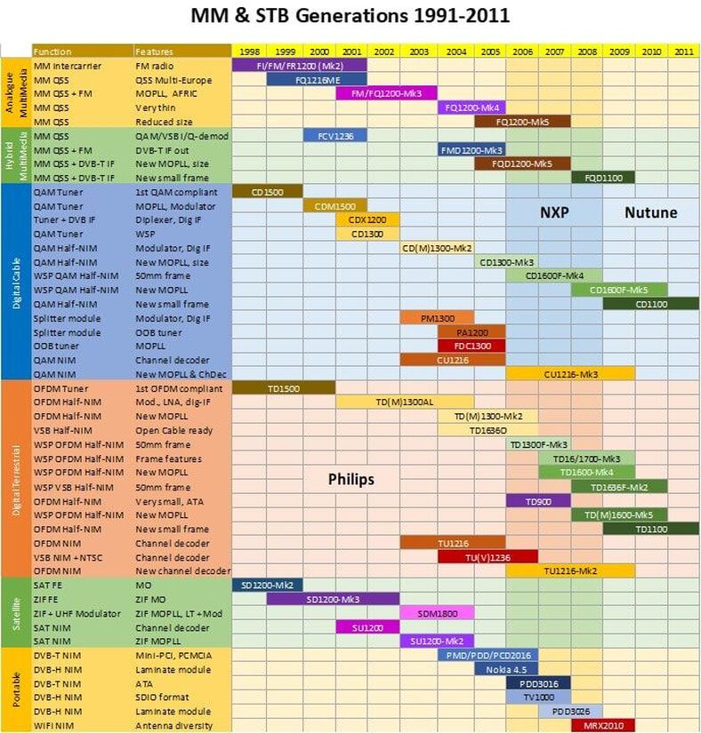
Overview of the non-TV products of the Philips BU Tuners and Philips/NXP BL RF Solutions from 1998.
Epilogue
If in the year 2000, where this chapter started, someone would have looked at the Philips TV and tuner-related business that person would have seen around 6Bio€ TV sales, 2,1Bio€ TV IC sales, and 150Mio€ Tuner sales. Who would have thought that 15 years later nothing of all these businesses was left, and that in the most literal sense: all development centres closed; with the exception of one or two all factories closed; no products alive with any root in the former Philips organisations, etcetera. The big question is therefore "where did it go wrong?", or "could it have gone a different, more positive way?" Although it was a complex constellation of businesses, playing on the components (ICs), modules and set level, it is possible to identify some of the root causes. Because most of the developments have been discussed in detail, I will only summarize the main topics:
But none of these developments killed the business, and in the end the cooperation within the verticals between BGTV (TV) and Digital Networks (STB), RF Solutions and Semiconductors continued, albeit more opportunistic and with more second suppliers. Where Philips really lost the battle was at the core of the TV function: the display. Although the trend to larger and flatter displays was correctly identified, Philips Research and Components tried to solve it in the classical Philips way: on its own, in a highly secret project, without partners, and focussing on technologies that were supposed to be superior because unique. This failed, but then it was too late to catch up in the development of plasma and LCD screens. When in 2006/7 the LCD screen emerged as the winner, Philips TV came into a negative spiral of business problems: margins of low-end LCD TV became too low, development and production of these sets was outsourced to Funai and TPV, these had no relation with Semiconductors and used Asian IC and module suppliers, Semiconductors consumer business dropped, and this took the heart out of the digital TV SoC development which only had high-end TV left as customer. In parallel Digital Networks had gone through a similar process, outsourcing the STB development and production with the same result. The Semiconductor failure in the mobile phone business, and the associated very high CMOS and SoC investments, further weakened the TV SoC development. From 2000 to 2009 the Semiconductor Consumer business shrank by a factor 3, the TV sales by a factor 2, and both were sold as fast as possible by a management that had no ambition to repair the business.
The Tuner and Tuner IC businesses are a slightly different story. Both maintained healthy market shares and were still seen as leading players in their segments. The BU Tuners/BL RF Solutions successfully made the transistion from analogue to digital tuners, despite many years of uncertainty in the market. Its main problems were again internal: it went through many years of organisational and strategic change, from BGTV to Consumer, to Corporate Redesign, to Semiconductors, and to NXP. One moment it was deemed strategic, the next it was up for sale, was split and then merged again. A lot of organisational distraction from focussing on the products, customers, and business. Nevertheless, it recovered from the turmoil and by 2007 sales were back and profitable at the year 2000 level, with the volume of modules at an all-time high of more than 50Mio. The same was valid for the BL TV Frontends, which survived the MOPLL to SiTuner migration, and had its all-time highest sales in 2008. However, both businesses were now part of NXP, and became the victim of the intrinsic lack of strategy of that company, which could not define anything better than "make at least 25% profit". Although both RFS and TVFE were healthy, profitable businesses, 25% EBITDA was a rediculous target; RFS typically made 30% gross margin, TVFE around 50%, both being players in the highly competitive consumer market. Also, as we have seen, big structural growth was very difficult to achieve given the high price erosion, both for the IC as well as the module. Both businesses therefore received the label "non-strategic and thus up for sale". In the meantime the profit had to be 25%, which meant that R&D had to be dramatically reduced, developments stopped (the IF business in TVFE, most new multi-radio applications in RFS). The portfolios of the the two BLs thus rapidly shrank to SiTuners only (TVFE) and digital cable and off-air tuners only (RFS). With these limited portfolios both businesses were hit head-on by the continuing market price erosion, but without any new business to compensate for this. Two clear examples of "cost cutting to death".
At the same time, it is fair to say that RF Solutions and TV Frontends have accelerated their fate by not co-operating on the SiTuner. Up to the last TDA6650 MOPLL it all went well, despite the substantial Infineon TUA6034 second sourcing. But with the SiTuner the discussions became entrenched: TVFE stating openly that they targeted only "tuner-on-the-board" in order to eliminate module makers like RFS, while RFS openly stated that SiTuners were not fit-for-use. However, when customers clearly showed they did not trust the tuner-on-the-board concept and preferred modules, while the performance of the TDA18251/71 third generation SiTuners had substantially improved, it would have been possible and logical to come closer and jointly develop SiTuners-in-a-can much earlier. Especially since they were now in the same BU Home! It would have saved Caen from its own - and effectively unsuccessful - laminate tuner module development. But the BU Home management was not interested in the RF business, seeing it only as a cash cow, and focussed on the TDA85500 problems. A joint activity on a SiTuner-in-a-can would have made NXP a leading player of what would become the standard solution in the market. Now the initiative was left to Sony, who came from nowhere and took the lead based on its vertical integration! It was only under Nutune and as late as 2011 that the SiTuner-in-a-can was developed, but that was already a doomed company and it could not save them.
However, apart from all that, there was one trend from which tuner development could not escape: tremendous price erosion due to technology evolution and integration. From the massive turret tuners of the 1960s that cost some 50 Dutch Guilders (in todays Euros probably around 500€) the price of a UV1300 WSP tuner had reduced to around 3USD by the year 2000 and would continue to decline to around 1USD for a SiTuner-in-a-can tuner. At these low prices and associated low margins such business, even as leading player in the 250-300Mio unit TV plus STB markets, is not interesting for the classial large players like Philips or NXP. The same is even more valid for the SiTuner semiconductor player, with a SiTuner sales price at 0,35USD or lower. Due to this price erosion, the tuner had also lost its strategic importance as the third most costly component in a CRT TV, which had always been the main reason for Philips striving to be the leading player in TV tuners: it was a strategic technology! When the dust settled on the digital-TV LCD sets, this was no longer the case: the screen and the digital TV SoC were the strategic core, a 2USD tuner no longer was.
The standard answer to this type of segment price erosion and strategic de-focus is portfolio diversification, a strategy especially pursued by Tuners/RF Solutions (first satellite, then multimedia, then mutli-radio, TVoM and Wifi). TV Frontend did the same on IC level with IF ICs and later new areas like RF Heating, White Spaces and digital processors. But for both BLs all these new activities were killed by higher management, ordering the BLs to focus on their "core" and not "waste" money on uncertain new developments. Unfortunately that core was rapidly declining, as we've seen, leading to the demise of both BLs.
One last observation has again to do with the top-down corporate policy. In the (distant) past, Philips also sold or spun out businesses: telecom (AT&T), white goods (Whirlpool), defense electronics (Thales), TV cameras (Bosch), and lithography machines ASML) are some of the many good examples. In all those cases Philips prided itself for taking care that the businesses landed safely and stably, with employment as much as possible intact. Sometimes it even rescued the spun out company from bankruptcy, like it did twice for ASML. However, starting with the Boonstra years this changed, continued under Kleisterlee and peaked under NXPs Clemmer. From now on divesting a business meant extracting the maximum amount of money and dumping the organisation in whichever company that was willing to pay. In most cases the effects were dramatic for the businesses sold: NXP was almost bankrupt within 2 years and only survived by dumping the mobile and home businesses, which then each had completely evaporated two years later; Nutune was a dead-born child from the beginning and effectively out of business in three years, and within two years under TP Vision all remaining Philips TV development and almost all production sites were closed. So, although there is nothing wrong with selling a business that no longer fits the strategy, the way it was done by Philips and NXP was destructive, often too late, and did not give the business - and especially its employees - a fair chance of success. It is unfortunate this happened exactly to the TV and Tuner businesses.
What is most surprising is that marketing and R&D from Tuners/RF Solutions/Nutune and TV Frontends simply kept on defining and developing new products, operations producing them and sales selling. Apparently undistracted by the increasing organizational chaos around them. As long as real re-organisations were kept away, the people simply continued to do their work. And what a work they did! I completely under-estimated the number of products developed in these last 15 years, both in terms of generations and applications, and the size of this last chapter has therefore considerably run out of hand. But there were so many products to be covered: the classical tuners and multimedia frontends, the last generations of LNB and satellite frontends, NIMs for all applications, many generations of digital cable and off-air tuners, but also amazingly compact portable tuners, TV-on-Mobile and WiFi modules. The same can be said of the Semiconductors/NXP activities on MOPLL, SiTuner, AFRIC and Master-IF, and channel decoders, but also discrete components like MOSFETs and amplifiers. It simply was a fantastic technology domain, broadcast RF reception, and it is amazing, looking back across the six chapters of Tuner History, to see how technology, performance and cost have evolved over the 65 years covered.
But the last words must be dedicated to the former Tuner colleagues. Apparently it was an addictive technology, since most people that worked in the Philips tuner groups either did it for many years (often their whole career), considered it the most enjoyable period of their career - like I did -, still possess impressive collections of hardware and/or data, and all are eager to share their memories and knowledge of the products and organisation. The regular former colleague reunions in Krefeld and Singapore are a testimony to this. Having talked with colleagues that started as long ago as 1965 in the Tuner Lab, down to the people that "closed the light" in 2011, and many in between, has allowed me to write this Philips Tuner History. Without them it would not have been possible to write it at this level of detail! I therefore hope that this story is not just a technology history of the tuner RF modules, but also a tribute to all the colleagues that developed, built, and sold these products.
Pieter Hooijmans
August 2021
- Starting with Boonstra as Philips president, the notion of vertical integration and its dependencies was dropped, and businesses were only judged on their internal results.
- The World Standard Pinning (WSP) turned out to be a strategic mistake: although it did open the wider market, it caused a devastating price erosion and made that Philips Tuners lost BG TV as a loyal internal customer. It took almost 5 years for RF Solutions to recover from the financial damage of the WSP introduction.
- The internal relation Tuners-Semiconductors remained bad throughout the last decade. Tuners/RF Solutions did the same to Semiconductors as BG TV did to them, mainly using Infineon MOPLLs and ST channel decoders. After the TUN2000 all new joint tuner IC developments stopped.
- This in turn made that Caen TV Frontends defined its primary strategy to be "Tuner-on-the-Board", trying at all cost to eliminate the module makers as their customers and "grab the added value of the module". This strategy utterly failed for the largest TV and STB domains, where customers demanded the application security of the module.
- Even when RF Solutions and TV Frontends were within the same BU Home of NXP the two businesses were not able to cooperate and develop a joint SiTuner-in-a-can solution. In the end both the module maker and the IC maker (RF Solutions and BL TV Frontend) lost in the market.
But none of these developments killed the business, and in the end the cooperation within the verticals between BGTV (TV) and Digital Networks (STB), RF Solutions and Semiconductors continued, albeit more opportunistic and with more second suppliers. Where Philips really lost the battle was at the core of the TV function: the display. Although the trend to larger and flatter displays was correctly identified, Philips Research and Components tried to solve it in the classical Philips way: on its own, in a highly secret project, without partners, and focussing on technologies that were supposed to be superior because unique. This failed, but then it was too late to catch up in the development of plasma and LCD screens. When in 2006/7 the LCD screen emerged as the winner, Philips TV came into a negative spiral of business problems: margins of low-end LCD TV became too low, development and production of these sets was outsourced to Funai and TPV, these had no relation with Semiconductors and used Asian IC and module suppliers, Semiconductors consumer business dropped, and this took the heart out of the digital TV SoC development which only had high-end TV left as customer. In parallel Digital Networks had gone through a similar process, outsourcing the STB development and production with the same result. The Semiconductor failure in the mobile phone business, and the associated very high CMOS and SoC investments, further weakened the TV SoC development. From 2000 to 2009 the Semiconductor Consumer business shrank by a factor 3, the TV sales by a factor 2, and both were sold as fast as possible by a management that had no ambition to repair the business.
The Tuner and Tuner IC businesses are a slightly different story. Both maintained healthy market shares and were still seen as leading players in their segments. The BU Tuners/BL RF Solutions successfully made the transistion from analogue to digital tuners, despite many years of uncertainty in the market. Its main problems were again internal: it went through many years of organisational and strategic change, from BGTV to Consumer, to Corporate Redesign, to Semiconductors, and to NXP. One moment it was deemed strategic, the next it was up for sale, was split and then merged again. A lot of organisational distraction from focussing on the products, customers, and business. Nevertheless, it recovered from the turmoil and by 2007 sales were back and profitable at the year 2000 level, with the volume of modules at an all-time high of more than 50Mio. The same was valid for the BL TV Frontends, which survived the MOPLL to SiTuner migration, and had its all-time highest sales in 2008. However, both businesses were now part of NXP, and became the victim of the intrinsic lack of strategy of that company, which could not define anything better than "make at least 25% profit". Although both RFS and TVFE were healthy, profitable businesses, 25% EBITDA was a rediculous target; RFS typically made 30% gross margin, TVFE around 50%, both being players in the highly competitive consumer market. Also, as we have seen, big structural growth was very difficult to achieve given the high price erosion, both for the IC as well as the module. Both businesses therefore received the label "non-strategic and thus up for sale". In the meantime the profit had to be 25%, which meant that R&D had to be dramatically reduced, developments stopped (the IF business in TVFE, most new multi-radio applications in RFS). The portfolios of the the two BLs thus rapidly shrank to SiTuners only (TVFE) and digital cable and off-air tuners only (RFS). With these limited portfolios both businesses were hit head-on by the continuing market price erosion, but without any new business to compensate for this. Two clear examples of "cost cutting to death".
At the same time, it is fair to say that RF Solutions and TV Frontends have accelerated their fate by not co-operating on the SiTuner. Up to the last TDA6650 MOPLL it all went well, despite the substantial Infineon TUA6034 second sourcing. But with the SiTuner the discussions became entrenched: TVFE stating openly that they targeted only "tuner-on-the-board" in order to eliminate module makers like RFS, while RFS openly stated that SiTuners were not fit-for-use. However, when customers clearly showed they did not trust the tuner-on-the-board concept and preferred modules, while the performance of the TDA18251/71 third generation SiTuners had substantially improved, it would have been possible and logical to come closer and jointly develop SiTuners-in-a-can much earlier. Especially since they were now in the same BU Home! It would have saved Caen from its own - and effectively unsuccessful - laminate tuner module development. But the BU Home management was not interested in the RF business, seeing it only as a cash cow, and focussed on the TDA85500 problems. A joint activity on a SiTuner-in-a-can would have made NXP a leading player of what would become the standard solution in the market. Now the initiative was left to Sony, who came from nowhere and took the lead based on its vertical integration! It was only under Nutune and as late as 2011 that the SiTuner-in-a-can was developed, but that was already a doomed company and it could not save them.
However, apart from all that, there was one trend from which tuner development could not escape: tremendous price erosion due to technology evolution and integration. From the massive turret tuners of the 1960s that cost some 50 Dutch Guilders (in todays Euros probably around 500€) the price of a UV1300 WSP tuner had reduced to around 3USD by the year 2000 and would continue to decline to around 1USD for a SiTuner-in-a-can tuner. At these low prices and associated low margins such business, even as leading player in the 250-300Mio unit TV plus STB markets, is not interesting for the classial large players like Philips or NXP. The same is even more valid for the SiTuner semiconductor player, with a SiTuner sales price at 0,35USD or lower. Due to this price erosion, the tuner had also lost its strategic importance as the third most costly component in a CRT TV, which had always been the main reason for Philips striving to be the leading player in TV tuners: it was a strategic technology! When the dust settled on the digital-TV LCD sets, this was no longer the case: the screen and the digital TV SoC were the strategic core, a 2USD tuner no longer was.
The standard answer to this type of segment price erosion and strategic de-focus is portfolio diversification, a strategy especially pursued by Tuners/RF Solutions (first satellite, then multimedia, then mutli-radio, TVoM and Wifi). TV Frontend did the same on IC level with IF ICs and later new areas like RF Heating, White Spaces and digital processors. But for both BLs all these new activities were killed by higher management, ordering the BLs to focus on their "core" and not "waste" money on uncertain new developments. Unfortunately that core was rapidly declining, as we've seen, leading to the demise of both BLs.
One last observation has again to do with the top-down corporate policy. In the (distant) past, Philips also sold or spun out businesses: telecom (AT&T), white goods (Whirlpool), defense electronics (Thales), TV cameras (Bosch), and lithography machines ASML) are some of the many good examples. In all those cases Philips prided itself for taking care that the businesses landed safely and stably, with employment as much as possible intact. Sometimes it even rescued the spun out company from bankruptcy, like it did twice for ASML. However, starting with the Boonstra years this changed, continued under Kleisterlee and peaked under NXPs Clemmer. From now on divesting a business meant extracting the maximum amount of money and dumping the organisation in whichever company that was willing to pay. In most cases the effects were dramatic for the businesses sold: NXP was almost bankrupt within 2 years and only survived by dumping the mobile and home businesses, which then each had completely evaporated two years later; Nutune was a dead-born child from the beginning and effectively out of business in three years, and within two years under TP Vision all remaining Philips TV development and almost all production sites were closed. So, although there is nothing wrong with selling a business that no longer fits the strategy, the way it was done by Philips and NXP was destructive, often too late, and did not give the business - and especially its employees - a fair chance of success. It is unfortunate this happened exactly to the TV and Tuner businesses.
What is most surprising is that marketing and R&D from Tuners/RF Solutions/Nutune and TV Frontends simply kept on defining and developing new products, operations producing them and sales selling. Apparently undistracted by the increasing organizational chaos around them. As long as real re-organisations were kept away, the people simply continued to do their work. And what a work they did! I completely under-estimated the number of products developed in these last 15 years, both in terms of generations and applications, and the size of this last chapter has therefore considerably run out of hand. But there were so many products to be covered: the classical tuners and multimedia frontends, the last generations of LNB and satellite frontends, NIMs for all applications, many generations of digital cable and off-air tuners, but also amazingly compact portable tuners, TV-on-Mobile and WiFi modules. The same can be said of the Semiconductors/NXP activities on MOPLL, SiTuner, AFRIC and Master-IF, and channel decoders, but also discrete components like MOSFETs and amplifiers. It simply was a fantastic technology domain, broadcast RF reception, and it is amazing, looking back across the six chapters of Tuner History, to see how technology, performance and cost have evolved over the 65 years covered.
But the last words must be dedicated to the former Tuner colleagues. Apparently it was an addictive technology, since most people that worked in the Philips tuner groups either did it for many years (often their whole career), considered it the most enjoyable period of their career - like I did -, still possess impressive collections of hardware and/or data, and all are eager to share their memories and knowledge of the products and organisation. The regular former colleague reunions in Krefeld and Singapore are a testimony to this. Having talked with colleagues that started as long ago as 1965 in the Tuner Lab, down to the people that "closed the light" in 2011, and many in between, has allowed me to write this Philips Tuner History. Without them it would not have been possible to write it at this level of detail! I therefore hope that this story is not just a technology history of the tuner RF modules, but also a tribute to all the colleagues that developed, built, and sold these products.
Pieter Hooijmans
August 2021
Picture of the Tuner Reunion on March 29, 2019 in Singapore, with many colleagues and their partners from Singapore, Krefeld and Eindhoven.
References
Data sheets and product information
The following former colleagues have contributed, and made it possible to figure out all the different product families that crowded these last years, as well as the many organisational developments. I want to thank them for patiently answering the never-ending series of questions from me:
- Around 2000 the BU Tuners still issued a few short but colourful product leaflets:
- UV1300-Mk3
- FM-FQ1200-Mk3, FCV1236
- CDX1200, CD1300, TD1300, PM1300
- SD1200-Mk3, SU1278-Mk1 and Mk2, SU1200-Mk2, SX719
- After a period of these product leaflets, the BL RF Solutions switched back to full data sheets, mostly pdf documents content-wise very similar to the orginal Data Books. Through multiple private sources I obtained the following data sheets, where I want to stress that most of these can not be found on the web and without the support of former colleagues it would have been impossible to write this story:
- UV1300-Mk3, UV1783-Mk3, UV1316-Mk4, UV1316E-Mk5, HD1816AF
- FI1216ME & MP-Mk3, FQ1216ME-Mk3, FQ1216MP-Mk3, FQ1216PN-Mk3, FQ1216LME-Mk3, FQ1216LMP-Mk3, FQ12136L-Mk3, FQ1256-Mk3, FM1236-Mk3, FQ1286-Mk3, FM1286-Mk3,
FQ1200A-Mk4, FQ1216AME-Mk4,
FQ1216ME-Mk5, FM1216-Mk5, FQ1236-Mk5, FM1236-Mk5, FM1286-Mk5 - FQD1216LME-Mk5,FQD1236-Mk5, FQD1236L-Mk5, FQD1286-Mk5, FQD1116ME, FQD1136
- SU1200, SU1278, SU1278-Mk2
- TU1216, TU1236, TUV1236, TUV1236D, CU1216, CU1216-Mk3
- CDX1216, CDX1236S, CDX1236CAGD, FDC1332, CD1316-Mk2, CD(M)1300L-Mk3, CD1616LF-Mk4, CD1686F-Mk3, CDM1636L-Mk5, CD1116ALS
- PM1314X, PMX1338, PS/PA1232D,
- TD1316, TD1344, TD(M)1300AL, TD(M)1300ALF-Mk2, TD1336O, TD1316-Mk3, TD1316ALF-Mk3, TD1311AF-Mk4, TD1311ALF-Mk4, TD1600ALF-Mk4, TD1636(E)F-Mk2, TD1717F-Mk4, TD1616AF-Mk5, TD1110ALS, TD1136
- PMD2016R, IPDC R4.5, PCD2016, PDD3016, BGT210, PDD3026, MRX2010, OM12001
- From 2004 RF Solutions re-started to issue product leaflets following the new Philips standards
- SU1200-CU1200-TU1200 NIMs, FQ1200-Mk5, FQ1216LME-Mk5, PMD2016R, PDD3016, BGT205
- In 2004 the new BL RF Solutions issued two booklets introducing their full product portfolio
- RF Solutions, Product Overview, February 2004 and October 2004
- From former colleagues, which will be thanked in more detail further down, I received diverse but always relevant reports related to product development:
- UV1316-Mk4 versus LG benchmarking, 2004
- FM/FQ1200-Mk3 Application Note, 2002
- FM1216-Mk3 Industrial Release gate report, December 2001
- FQ1200-Mk5 product improvement objectives, 2005 and FQ1200-Mk3 to Mk5 transition plan, 2004
- FCV1236D draft Product Range Start, June 1999
- TU1216 Evaluation Report by Philips Semiconductors Rennes, April 2003
- TU1236 Product Range Start document, May 2002
- FMD1216ME-Mk3 Design Release gate evaluation report, September 2004
- FMD1216ME-Mk3 Evaluation Report amplifier issue, September 2005
- CU1216LS-Mk3 circuit diagram and parts list, 2005
- FQD1200C Product Range Start document, September 2006
- FRH2000, FWH2000 Product Range Start document, March 2006
- FQD1100 Product Range Start, Bill-of-Material, September 2007
- CD1600-Mk4 Bill-of-Material, 2009
- TDA8270 Evaluation Report, Krefeld Tuner Competence Centre, April 2002
- TDA18271 Evaluation Report, Singapore Tuner Development, September 2006
- TD1300-Mk2 alignment instructions, 2004
- TD1300-Mk3 Schematic diagram, 2006
- TD1716F Bill-of-Material, 2006
- TD1116 Bill-of-Material, 2009
- PDD3016 Schematic diagram and Bill-of-Material, 2005
- PDD3016 and ANT2216 Application Note, August 2006
- PDD3026 Schematic diagram, 2007
- From the Nutune period mostly single page product leaflets can be found:
- FT3300, FH2600, FC2220, FJ2200
- FJ2328 Data Sheet
- For ICs and discrete semiconductors (varicaps, MOSFETs, transistors) it is all much easier: almost all Data Sheets can be found on Datasheet Archive. This includes the Philips Semiconductors and NXP, Infineon, Sanyo, NextWave, ST, TI and Toshiba ICs that have been used and described.
- Philips Semiconductors brought out many applications specific Reference Designs, often including a tuner module and/or Si Tuner
- PC-TV "Europa" (SAA7134 and TD1316/44), 2001
- PCI TV "Antigua" (SAA7133 and FQ1236/86-Mk3), October 2002
- PCTV "Crete" (SAA7146 and CU1216), 2002
- PC DVB-T "Tenerife" (SAA7146), 2002
- DTT STB (PNX831x, TDA10046, TD1316L), 2003
- Nexperia IBO2525-X (PNX8526 and TDM1316AL), 2003
- PCI DVB-T Hybrid (SAA7134, TDA10046 and TD1316), 2003
- LCD TV 7154 (SAA7154 and FM1200-Mk3), December 2003
- Nexperia Cable STB (PNX831x, TDA10023, TDA8274), 2004
- Si Tuner for PCTV (TDA8275A), 2004
- Nexperia STB200 (PNX831x, TDA10086, TDA18262), 2005
- Dual hybrid DVB-T PCTV (SAA7162, TDA10046, TDA8275), 2005
- PCV220 DVB-T (SAA7160, TDA10046, TDA8275A), 2006
- TV520 Digital TV system (PNX8536, TDA10048, TDA9898 MasterIF, TD1716F), 2006
- OM5775 PC-TV (SAA7162, TDA10048, TDA18271), 2006
- PCV530 (SAA7164 and FQD1236-Mk5 plus FMD1236-Mk3), January 2007
- STB215 (PNX8329, TDA10023, CD1616, TDA8271A), 2007
- TV522 Hybrid LCD TV (PNX8541, TDA10048, TDA9898 MasterIF and TD1716F), 2007
- OM57776T (TDA10048, TDA18211), 2007
- OM5785C DVR and STB (TDA10023, TDA8295, TDA18251), 2007
- PCV540 (SAA7163, TDA10048, TDA18271), 2007
- TV542 full HD TV (PNX8542, TDA10048, FQD1116, TDA18271), 2007
- OM3865C Cable STB (TDA10024, TDA18252), 2008
- OM3910/11/12/39 hybrid TV FE (TDA18273), 2011
- OM3914 Zapper STB NIM (TDA10024, TDA18250), 2011
- OM3917-OM3834 Cable STB (TDA10025/27, TDA18260), 2011
- Application Guide Flat-Panel TV (TDA8296, TDA18273), 2012
- "NXP in the making - the world's first HPMS company", April 2010. This book was written by a group of NXP old hands, including myself for the chapter on RF, summarising the history of Philips Semiconductors and NXP in analogue mixed-signal technology and product segments. For many technical questions a very useful source.
- "50 years towards living technology - A biography of the System Labs Eindhoven", Philips Semiconductors Jubilee book 1952-2002. Contains nice stories about early developments.
- For explaining the ATSC 8-VSB standard I used "What exactly is 8-VSB anyway?" by David Sparano.
- Elektrotanya remains the by far most important source of TV service manuals, of which I use a large pile to analyse the TV system trends.
- Similarly, Datasheet Archive is the general source for IC and component data sheets.
- Wikipedia remains a great source for technical background stories on e.g. standards and technologies, and historical data on companies.
- The years covered in the last chapter, 2000 to now, were the new Internet era, with a whole new approach to products and data. One of my main sources for product information and nice pictures is the endless number of sites that offer tuners, TV or STB main boards, or entire sets for sale. Always with pictures of the products for sale. I have chosen not to reference these sites, so product pictures without a reference are simply from "the Internet" in general.
- Similarly, there are many forums and hobbyist sites with often very detailed information and technical pictures on (Philips) TV sets. Where possible they have been referenced.
- Maarten Bakker, active on many TV fora, has been very helpful in unraveling Philips TV platforms and chassis, type numbers, the TPV relations, factory codes and more.
- "Analoge polyfasefilters", Eduard Stikvoort, Philips Research Labs, NERG presentation, March 2003.
- "SiP Tuner with Integrated LC Tracking Filter for Both Cable and Terrestrial TV Reception", Jean Robert Tourret, Sebastien Amiot, Maxime Bernard, Mohamed Bouhamame, Claude Caron, Olivier Crand, Gilles Denise, Vincent Fillâtre, Thibault Kervaon, Markus Kristen, Luca Lo Coco, Frederic Mercier, Jean Marc Paris, François Pichon, Sébastien Prouet, Vincent Rambeau, Sebastien Robert, Jan van Sinderen, and Olivier Susplugas, IEEE Journal of Solid State Circuits, Vol. 42, No. 12, December 2007.
- My own notebooks and files from the years 2000 to 2014, when Research Group Leader of RF Transceivers, RF Program Manager in Philips Semiconductors, and BU R&D and Strategy manager in the NXP BUs MMS, HPMS, I&I and S&C.
The following former colleagues have contributed, and made it possible to figure out all the different product families that crowded these last years, as well as the many organisational developments. I want to thank them for patiently answering the never-ending series of questions from me:
- Darko Jancin has given many high-quality copies of the official publicity pictures of tuner modules.
- Henk van der Wijst made good high quality pictures of the several tuner samples in his possession.
- Jan van Daal gave me some samples from his collection, including the unique TD900, TV1000 and SU1200.
- Detlef Marbach sent good quality pictures of some unique samples from the last RF Solutions period.
- Oswald Moonen provided data sheets of the proprietary ICs like the TUN2000 and any NXP ICs I was not able to find data sheets.
- Ron Schiltmans remembers every detail of the LNB products and talked me through all designs and the organsation.
- Kwong Kam Choon provided background and sample pictures regarding the Singapore tuner development.
- Toh Kong Lim remained the enthusiastic and always available point of contact regarding the Singapore activities. He has also proof-read the whole chapter.
- Lim Kui Yong, as one of the last employees of Nutune, explained to me the final years of the company, including some useful data and product data sheets.
- Edward Ng sent me his whole file archive on the period 2000-2006, allowing me a lot of insight into the RF Solutions portfolio management, but also on unknown products, the organisation and manufacturing.
- Thomas Fenkes was this chapter the absolute support champion. Based on his enormous archive I could ask any question on any product, and he would provide data sheets, circuit diagrams, layouts, bill-of-materials and more, that were essential for writing this story.
Update history
August 2021
- First upload
- Added nice pictures of the CD1316-Mk2 Twin Tuners and their Humax IPVR application, received from Maarten Bakker.
- Added section on (failed) techniology investigations for cost reduction: laser alignment (information from Martin Barnasconi) and Chip-on-Board (information from Darko Jancin).
- Added nice pictures of the Nutune FJ2209 tuner, received from Maarten Bakker.