Introduction
Although a lot of data can be found on the first computers and their applications, it is rare to find detailed descriptions of their inner structure and working. The Philips CAB TRANSDECO is an exception, of which I obtained a full and detailed description. This description is summarized in the booklet Philips Computer Circuitry Considerations from March 1960. Just for the fun of it I'll copy some of the circuits and descriptions of this first transistorized computer, with the focus on the internal number structure and processing.
The internal counter and transport basics
|
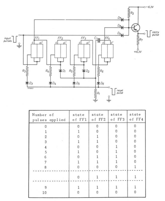
One of the main differentiating characteristics of the TRANSDECO was that it did not use binary but decimal number representation. These number states were captured in the decimal counter already introduced on the main page, but repeated here. Main specificities were the jump at state "8" to what would be called "14" in binary coding and subsequently binary "15" for state 9. This allowed the jump back to state "0"at the tenth input pulse. At the 10th pulse also a CARRY pulse was generated.
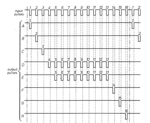
The next critical issue was how to transfer the state of a counter to another counter. For this the entire computer operation was done in main cycles of 16 clock cycles. In a dedicated Pulse Pattern Generator (PPG) these 16 clock cycles were separated into eight different pulse patterns, called A to H. These eight control signals were used in every other module of the TRANSDECO for transporting and processing data. |
From these control signals, A-C and F-H were used to start and stop activities. The ten D pulses were used to cycle a decimal counter through a full ten cycles, after which it would be back in its original state. The nine E pulses were used to clock a decimal counter that had been reset to 0.
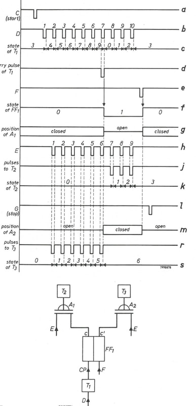
Before looking how the control pulses were used to move numbers between counters, it should be noted that negative numbers were represented as the 9-complement of their positive equivalent. It is interesting to note that when the nine E-pulses are divided between two counters (in any combination) the contents of the counters will always be each others 9-complement: from 9-0 to e.g. 3-6 and 0-9. How the content transfer works is illustrated in the diagram on the left. In this example the content of decimal counter T1 (which is here as example is assumed to be 3) is transferred to decimal counter T2, which is in the initial state 0. In the course of this main cycle T1 receives the 10 D-pulses (signal b), which essentially make it count from 3 to 9 and then, after reset, from 1 to its original state 3 (signal c). At the end of the main cycle the content of T1 has not changed. In parallel T2 receives (starting one clock cycle later) the D pulses, but only after AND-gate A1 is opened by control signal c which is the output of FF1 (signal g). And FF1 only jumps to 1 when it receives an input CARRY-pulse from T1 (signal d), which was after 7 D-cycles when it reset to 0. In this case only the last three E-pulses are passed to T2 (signal j), such that T2 counts to 3 (signal k), which was exactly the content of T1. Interestingly, by duplicating the decimal counter T3, but using the complementary output of FF1 (signal m) the counter T3 will receive the first six E-pulses through AND-gate A2, making this counter count to 6, the 9-complement of the content of T1. Pulse F resets FF1 and stops the process. The start C-pulse (signal a) and stop G-pulse (signal l) have no active role in this case. So, with this transport circuitry, 100% hard-wired gated logic, the content of a counter can be transported (essentially copied) to another counter, while at the same time its 9-complement is transported to a second counter. |
Representation of numbers
|
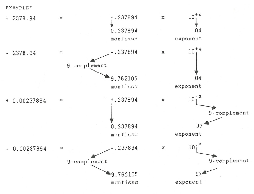
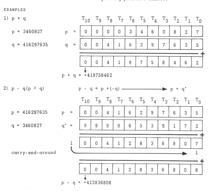
The section above treated the setting and transport of one single decimal digit between 0 and 9. For numbers multiple digits were required. The internal representation of a number was in floating point: a ten digit fractional mantissa with a sign digit in front, plus two digits exponential. Examples are given on the right. One aspect that will come back is the formal representation of a negative number. If we take the 11 digits 0 of the "positive" number zero (0-0000000000) , the 9-complement of it is ten 9's (9-9999999999). So, in the TRANSDECO the first digit indicates the sign: 0 = positive, 9 = negative. However, the 9-complement representation of "negative zero" is the number 10^11 - 1. This is important to keep in mind when numbers are added in the accumulator. If in a subtraction the 1oth bit overflows to a number higher than 9 the virtual 11th digit becomes 1. In this case a so-called CARRY-END-AROUND is implemented, meaning that the mentioned number 10^11 - 1 is subtracted from the outcome. In practise this means that the 11th digit is deleted and 1 is added to the least significant bit. Examples are shown on the right.
These additions are performed, as in all computers, in the accumulator, which is illustrated below and works as follows. At the start (after reset in a previous addition action) the accu selector binary counter is in state 0. This selects the leftmost gate A10, which will pass through the number of pulses belonging to the most significant digit 10 (in fact the sign of the number, so either 0 or 9) to accu counter T10. The content is represented by a series of D-pulses coming from another register as described in the first section, which is entering on line P and passed through the active AND-gate An to the selected counter Tn. At the end of the first 16-clock main cycle an F-pulse ends the action and makes the accu counter increase by 1. This will select A9 and the next counter content will be added to T9. And so forth, until the 11th main cycle will select A11 that will only pass the G-pulse to reset the accu selector to zero. |
|
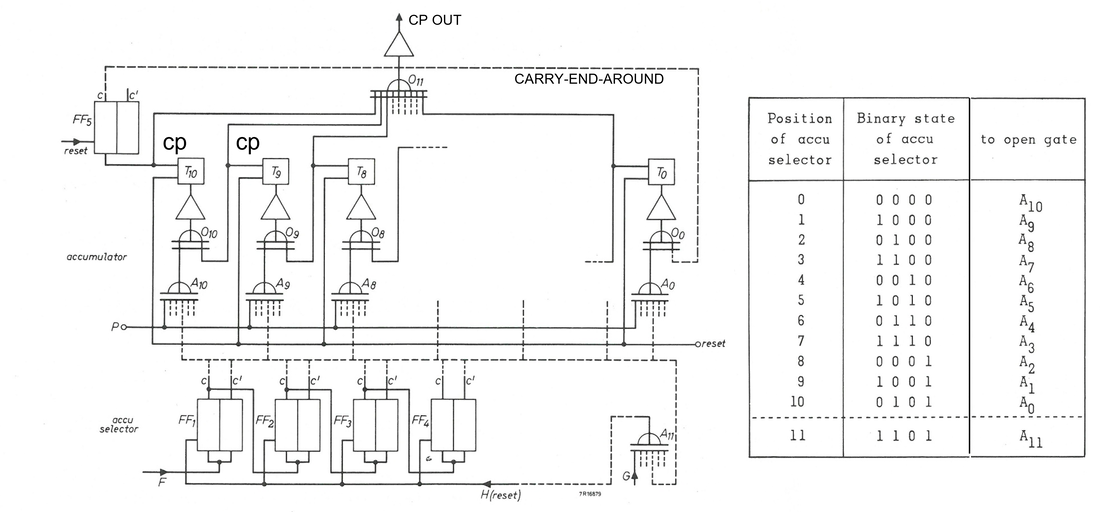
Block diagram of the mantissa accumulator. P is the input from the 10 digit registers containing the numbers to be added. Decimal counters T10 (most significant digit) to T0 (least significant digit) at the end of an addition cycle contain the sum. On the right the table illustrating the relation between the accu selector state and AND-gate selection. CP are the carry pulse outputs
For an addition operation the same 11 cycles are performed, but without first clearing the state of the decimal counters. Each of the decimal counters will thus start counting from its content of the first number. If a counter cycles through 9 a carry pulse (CP) is generated that passed through the OR-gate of the previous counter which is thus increased by one. This is the reason all number operations in the TRANSDECO start with the most significant digit. When the T10 counter overflows the carry pulse is passed to Flip-Flop5 (FF5) and the CARRY-END-AROUND line goes high, increasing the counter T0 by one. Also the addition cycle takes eleven main cycles of 16 clock pulses.
Once the sum of the two numbers is in the accumulator registers T10-T0, a third cycle reads out the accumulator, transferring its content to another (storage) register. The accu selector again cycles through all 11 registers and A11, but this time each decimal counter Tn receives the standard 10 D-pulses. In exactly the same way as described in the first section, each counter cycles 10 steps back to its original content, with the carry pulse CP sent when the content jumps from 9 to 0. All these CP pulses are sent to the output CP OUT through OR-gate O11, which connects to the receiving counters in the standard way. One interesting issues is that when this CP is sent by a counter Tn, the carry pulse is still connected to Tn+1, which has been read out in the previous main cycle. Tn+1 is therefore increased by one. This means that at the end of the accumulator read-out the content has been modified, in fact all counters have increased by one. The content of the accumulator can therefore no longer be used and all counters are reset. This is also the reason why all operations start with the most significant number.
The core addition operation of the mantissa accumulator thus takes 3 accu cycles of 11 main cycles of 16 clock cycles, or 3 x 11 x 16 = 528 clock cycles. At the master clock rate of 150kHz this took 3,5ms. In exactly the same way a 2-digit accumulator handled the exponentials.
Micro-programming
At the highest level the TRANSDECO could execute 12 so-called sub-routines. The four basic operations (add, subtract, multiply, divide), three internal programming operations (transport, conditional jump, stop), two input instructions (for instructions and numbers) and three output instructions optimized for the electronic type writer (tabulate, write and carriage return). Each of these sub-routines required multiple internal operations, which were called micro operations. These micro operations were divided into two sub-sets. The first group (OS2=0) contained only 5 micro-instructions, but these were executed at the beginning of every instruction cycle. They essentially prepared the computer for the operation to be performed. At the end of these five cycles the computer conditions were as follows:
- content of address counter AC1 = p (address of A)
- content of address counter AC2 = q (address of B)
- Position of instruction selector IS1 set to instruction number to be performed (e.g. addition =1)
- Position of operation selector OS1 to 000 (micro-instruction 0)
- Position of operation selector OS2 to 001 (first sub-group 1)
- Position of conditional flip-flop CF3 to 1 (when triggered the micro-operation sequence is ended)
|
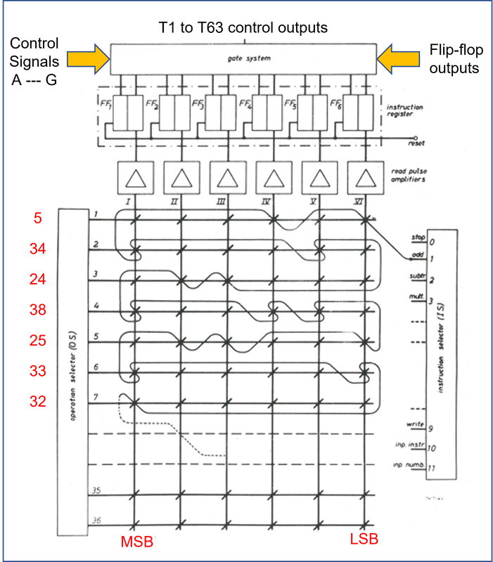
Like all other functions of the TRANSDECO, also the micro-instructions were hard-coded into the computer. For the instructions a dedicated memory was available, with the micro-instruction numbers woven into the magnetic core, see the figure on the right. In this example the Instruction Selector (IS, on the right) is set to 1, meaning the sub-routine Addition is to be executed. The output wire of IS=1 is now woven through the core memory in such a way that it only passes through cores that represent the binary code of a micro instruction. In this case the first row will be read out when the Operation Selector output is 000001 (1), in which case only the first and third columns of the matrix provide a pulse, equivalent to binary 5. So the number of the first micro instruction is 5. In the same fashion the next micro instructions are 34, 24, 38, et cetera. When a micro instruction is read out the equivalent Instruction Register Flip Flops FF1 to FF6 are set, which in turn set the Gate System switching matrix. In this matrix the pulse trains from the control Pulse Pattern Generator (PPG see above) and the different outputs of the state monitoring flip flops are directed to the 64 different control inputs of the TRANSDECO. Obviously, this memory contained rather large cores, because theoretically up to 14 wires had to be passed through: the two horizontal and vertical read out wires plus twelve wires of the instructions.
|
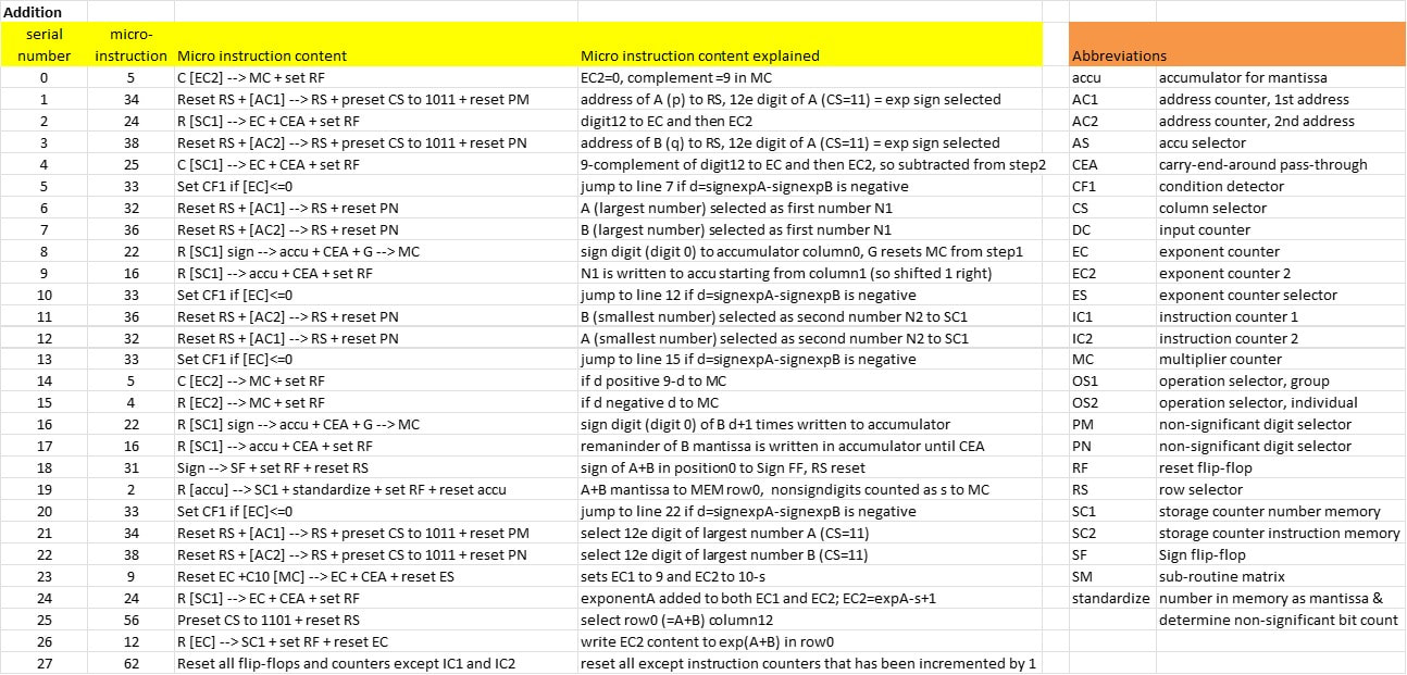
The details of the instruction Addition are now as shown in the table below. The principle is as follows, assuming number A is given as ZAAAAAAAAAYEE, with Z the sign of the mantissa (0 or 9, with 9 meaning negative), AAAAAAAAA the 9-digit mantissa, Y the sign of the exponential and EE the exponential. Similarly B is ZBBBBBBBBBYFF. The first steps (0-7) are to determine which of the two is the highest number (with the biggest exponent) and then the difference in exponent d=EE-FF (assuming A is the largest number, otherwise the inverse). Once this is known, the mantissas are modified as ZZAAAAAAAA (line 9) and YYYYYBBBBB (line 16), that is the largest number is shifted one position to the right and the smallest number is shifted d+1 positions to the right (here d is taken as 3). In a regular accumulator operation these are then added (line 17) and written into memory row 0 in the standardized way (line 19), meaning that the additional insignificant zeroes are eliminated. The number of those insignificant zeroes that is eliminated is counted as s (for addition s is always 1 or 0 in case of a carry-over). The final exponential is then written as EE+1-s, which is either EE or EE+1 in case of a carry-over (line 26). The outcome in the standard form ZCCCCCCCCCZGG is now in memory location row 0, while all counters and flip flops are reset except for the Instruction Counters , which have been increased by 1 to execute the next execution.
Programming the TRANSDECO
|
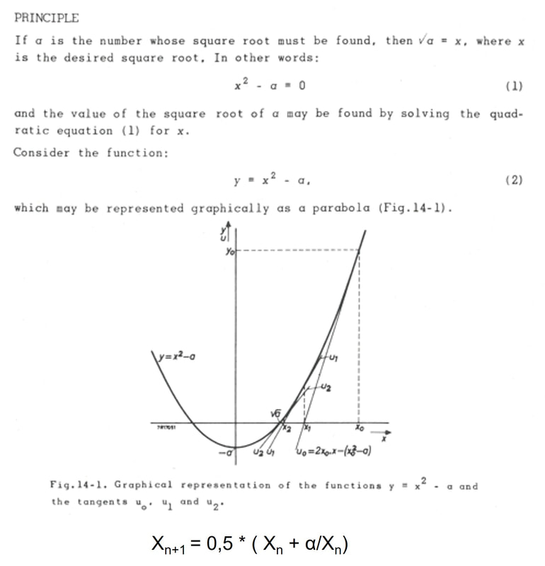
The final step is now the real use of the TRANSDECO for computations. I will simply copy the example from the booklet, which is the calculation of the square root of the numbers 10 to 30 using the Newton-Raphson iteration method described on the right. The iterative computation is shown at the bottom, which shows how the next iteration Xn+1 is computed from the target number alpha and the last iteration. For the first iteration X0 is usually taken as alpha.
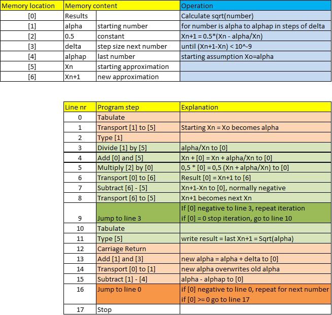
The program part doing these calculations as written for the TRANSDECO is shown below, where it starts after the starting values have been properly input to the proper memory locations as listed. In this case alpha=10 (the starting number), delta=1 (the increment of the numbers to be calculated) and alphaP (the last number) =30. The program iterates until the least significant bit of the mantissa in the check Xn+1-Xn (line 7 and 9) has become 0, which is equivalent to a computation with an accuracy of 10^-9. |
|
According the booklet the execution of this program too 2 minutes 50 seconds from start to stop, or roughly 8,5 seconds per number. A large part of this period will have been used by the write command, which operated a set of electron-mechanical relays to control the electronic type writer. The output driver operated on the basis of a 25ms pulse generator, so 40Hz, instead of the 150kHz of the TRANSDECO core.
Although in today's eyes these are fairly standard operations, it should be remembered that this was the first all-transistor, totally hard-wired computer, with a bulky electro-mechanical type writer output, in 1958. As such it was a very impressive achievement! All based, as described, on flip-flop circuits, discrete AND and OR gates, and a ring core memories. Especially the micro instruction memory, containing the hard-wired instruction codes woven into the memory fabric, was a very dedicated piece of engineering. Most remarkable on the TRANSDECO was its reliance on real decimal numbers, instead of the binary numbers we now associate with digital computers. All in all it was a remarkable piece of engineering! |
The program contains two loops, terminated by jump instructions. The first loop, green in the table, performs the NR-iteration as described. In line 7 the difference between the last two iterations Xn+1-Xn is computed. Normally this outcome is negative, in which case the program executes the conditional jump back to line 3 for the next iteration. If the difference has become zero, i.e. smaller than the least significant bit, the program continues with the next line (10). The result, so square root alphaN, is then printed by the electronic type writer.
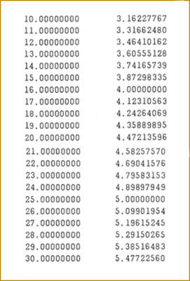
The program then continues with the next loop, i.e. calculating the square root of the next number (alphaN + delta, in this case alphaN +1). The second jump command (line 16) checks whether the new alphaN-alphaP is still negative, i.e. alphaN is still smaller than the stop number alphaP. If so the program jumps back to line 0, otherwise (in case the outcome is equal or bigger than 0) the program continues with the next line 17, which stops the execution. The result for the parameters alpha=10, delta=1 and alphaP=31 are shown below. |
Literature
All details and pictures on these page have been taken from a single source:
Philips Electron Tube Division & Philips Industrial Components and Materials Division, Series Computing and Control, Computer Circuitry Considerations, Eindhoven, 1960.
This booklet, which can't be found on the internet, I obtained from ing. Wolf Schieber, the engineer who co-developed the TRANSDECO in 1956-58 when working in the Centraal Applicatielab Buizen (CAB) or Dammers-lab in Eindhoven.
