Introduction
|
Depending on how one looks at it, technology developments can branch out or happen in parallel, converge again or diverge into completely different directions. One such development is the introduction of digital circuitry and computing. Although ultimately digital and analogue electronics diverged into quite separate domains, they had a common origin: the first transistors in the 1950s. Within Philips several activities described on other pages of the Technology History section came together for this new activity:
As most of the other stories on (Philips) technology history I'll try to put it in a broader perspective. Because half the western world was working on the new digital and computer technologies, it goes way too far trying to describe all developments. So I'll limit myself to two other tracks:
|
Chapter Navigation
|
World-wide computer development up to 1955
Like the television and radar advanced electronic systems, also the development of (digital) computers started in the second half of the 1930s in multiple countries and many institutes. After the outbreak of WW2 all developments that were allowed to continue were done in the context of military applications, like code breaking (Alan Turing's Colossus from 1943) and simulations of nuclear devices (the Harvard Mk.I from 1944, still a purely relay-based electro-mechanical machine) or ballistic trajectory computation (1945 ENIAC of Pennsylvania University for the US Army, with 16.450 valves). In 1949 the UK Manchester Mk.I was the first to run stored programs, using the first drum magnetic memory. Although the first valve-based computers appeared around the same time, during the early 1950s most computers continued to be based on electro-mechanical relays for switching. But in 1951 the first valve-based and series-produced computer was launched by US company ERA, the 5.200-valve UNIVAC, followed the next year by the IBM 701 of which 14 were produced, mainly for military or scientific applications.
|
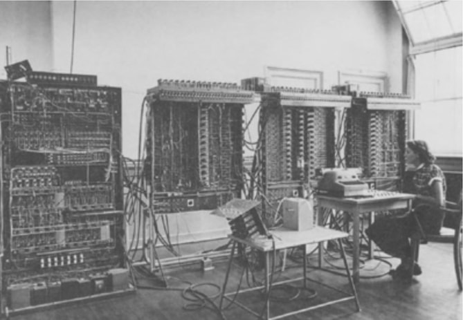
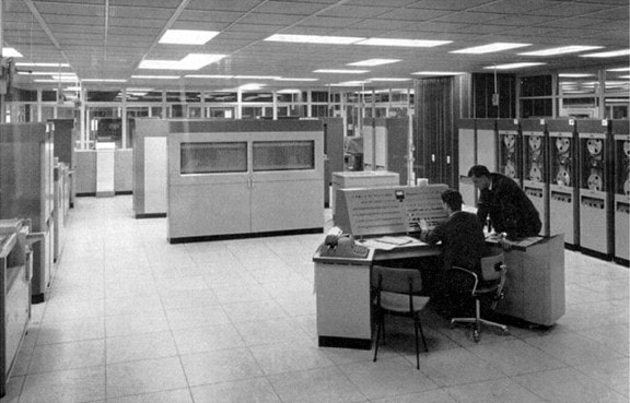
The first real mass-produced computer was the IBM650 from 1954, of which some 2000 were manufactured for business applications. At this time the state-of-the-art was based on valves (many hundreds per machine, in principle one per flip-flop circuit), magnetic drum memories that could store a few thousand words of typically 8 bits, paper tape program input, von Neumann architectures using stored programs and arithmetic units, clock speeds in the kHz range and memory access times in the ms range. These computers, like most equipment of the time, were housed in multiple cabinets fully occupying a typical large office room, while power consumption could be in the order of 70kW (like the IBM705). That in turn required massive cooling measures, based on air flow or liquid cooling, burning additionally half as much power as the computer itself. Especially IBM started the use of standardized modules, initially containing a single dual triode valve, later moving to multiple valves. The ambition of electrical functional standardization had to be given up, though, but these modules provided at least a standard mechanical and electrical interface. The strive for more electrical standardization would not be gone, however. Another ambition was to get rid of the vacuum valves, given their power consumption, heating problems and associated life-time problems. (A typical valve-based computer like the IBM700 family would fail every eight hour due to malfunctioning valves).
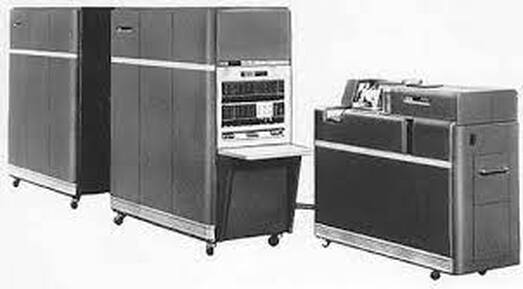
The IBM 650, the first computer designed specifically for business (administrative) applications.
|
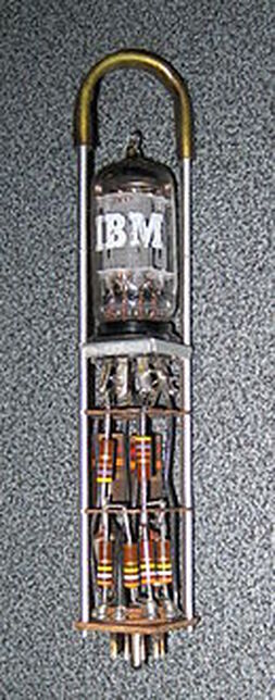
An early single-valve pluggable IBM module using a single dual triode. [Wikipedia]
|
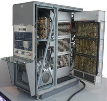
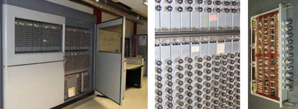
An IBM650 with opened side door. Lower left the magnetic memory drum module. To the right two full racks of 8-valve electronic modules. Each door contains three blocks of some 30 8-valve modules, so 240 per block, 720 per door, three doors is around 2200 valves in this main cabinet. [Radiomuseum]
|
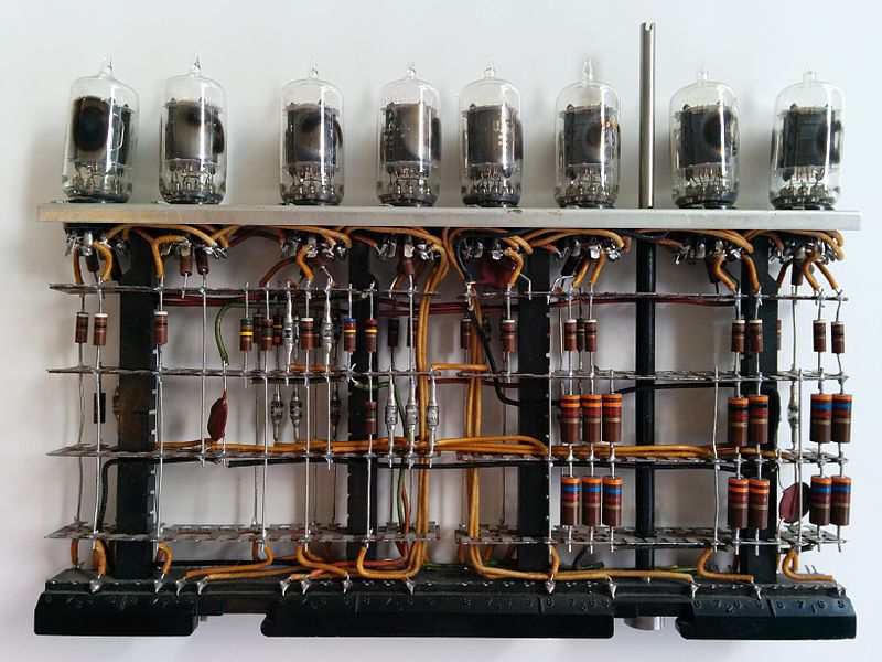
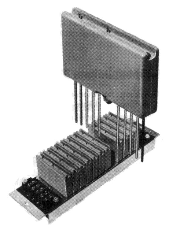
A typical 8-valve pluggable module from the IBM650. All valves seem to be identical dual triodes. The rod between the 6th and 7th valves is for the locking mechanism of the module. [Wikimedia Commons]
|
Computer developments in the Netherlands, 1950-1955
The first activity in the Netherlands, and at least initially the most visible, was at the Mathematics Centre of the University of Amsterdam. This group led by Adriaan van Wijngaarden started around 1950 with the Automatische Relais Rekenmachine Amsterdam (ARRA, Automatic Relay Computer Amsterdam). It was ready in 1951, but worked only once and the official opening ceremony became an embarrassing failure. In 1952 they started development of an all electronic computer, with the focus on reliability for operations. It used advanced concepts like a modular approach, standard components and a distributed clock signal for better control and synchronization. The prototype was ready by January 1954 and baptized ARRA II. One machine operated satisfactorily in the Mathematics Centre and a copy was built for aircraft maker Fokker, which used it for modelling the highly successful Fokker F.27 Friendship airliner. In 1955 the MC-group started on the successor, which introduced a small magnetic core memory that functioned as an instruction cache memory between the processor and the slow disk memory, and thus substantially improved instruction execution speed. But before this next generation computer was finished the activities of the Mathematisch Centrum were moved into a new company, which targeted commercial production and sale of the computer, N.V. Electrologica. This was 1956.
The ARRA computer of the University of Amsterdam Mathematics Centre, from 1951. It was clearly not a machine engineered for reliability and in the end did not work. It was quickly succeeded by the ARRA II in 1953. [DBNL]
The PTT PTERA, 1953
|
The other significant computer development activity in the Netherlands during the early 1950s was in the Centraal Laboratorium (Central Laboratory) of the Dutch Staatsbedrijf der Posterijen, Telegrafie en Telefonie (PTT, the national postal, telegraph and telephone service). Like many European countries also the Dutch PTT had its internal development activity, with the main focus on radio equipment for the long distance telegraphy connections, and high capacity telephone (mostly wired) transmission equipment. Since January 1950 all PTT technology development was combined into the single Centraal Laboratorium, most of which was housed near the PTT headquarters in the Kortenaerstraat in Den Haag (The Hague). In 1950 some 200 people worked in the CL, of which 8 in the Mathematische Afdeling (Mathematics Department) under dr.ir. Leen Kosten. Kosten's group was under much pressure to come with tools for simulating telephone traffic and especially blocking probabilities, which was impossible to do with classical computational methods. Kosten therefore pushed, and obtained permission, to work on the development of a computing device for the PTT. For this he hired ir. Willem van der Poel, freshly graduated from the Technische Hogeschool (Technical University) Delft where he had designed a first computer called TESTUDO, which was actually built and, although very slow, used for practical computations until 1964!
Van der Poel started developments with the Zeer Eenvoudige Reken Otomaat (ZERO, the Very Simple Computing Machine), essentially a technology demonstrator for a flexible architecture based on the use of multiple but small so-called micro-instructions. The ZERO was made as simple as possible, and could for example not make multiplications of divisions. These were both made by repeated additions or subtractions. The ZERO therefore had just seven different instructions that were programmed by just four bits, as listed below:
|
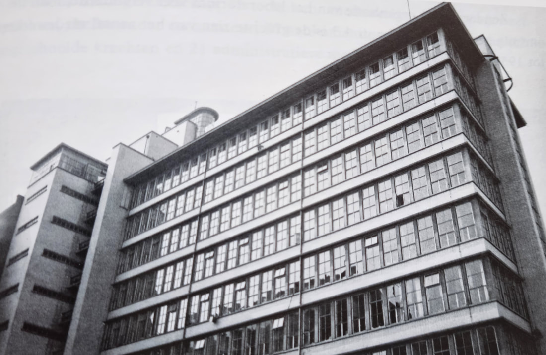
The building housing the Centraal Laboratorium of the Dutch PTT at the De Ruyterstraat in The Hague. Here van der Poel developed the PTERA computer.
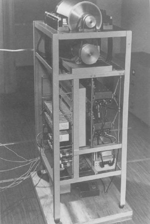
One of the most critical elements of the PTERA, its drum memory, seen here on tob of the rack with the belt-driving motor below. [DBNL]
|
Evidently, only the On and An instructions actually performed an arithmetic operation, addition or subtraction, in line with van der Poel's theory of as-simple-as-possible computing. He received international fame with these theories. The ZERO was completed in 1952 and operated for 14 days, after which it was taken apart for the components to be re-used in the first real machine, the PTT Elektronische Reken-Automaat (PTERA, PTT Electronic Computing Machine). There was quite some pressure on the Mathematische Afdeling of Kosten to have a computer available, and development was rushed as much as possible, using material and technology that was available (including, as mentioned, the cannibalized ZERO components). The PTERA main characteristics were as follows:
- a drum memory, rotating at 2400 rpm, with 32 tracks, each containing 32 registers of 30 bits. The total memory content was thus 32 x 32 = 1024 words of 30 bits. A register could contain either a number of an instruction, but only one track could be read at a time. The bit reading speed was thus 38kb/s and it took 550us to fetch a full word.
- if a register contained a number, it had to be presented as a fraction between -1 and +1.
- if a register contained an instruction, it was formed from two parts. First 12 bits defined the location on the memory drum on which the operation was to be performed: 6 bits for the track and 6 bits for the location within the track. The next 6 bits were used to define one of the 54 different operations, which were organised in 12 groups (essentially an extended list of the ZERO above, but including multiplication and division.
- the PTERA had four registers: A (accumulator), B (support accumulator), C (control register) and R (relay support register). In case of a multiplication the A and B accumulators were combined to form a (temporary) 60-bit word.
- the PTERA was built using around 700 vacuum tubes, probably mostly E80CC double triodes. Especially the R-register was still built using relay, of which some 120 were used. Total power consumption was 6kW.
- input was read using telex punched tape and read at 20 characters/s. For the output a a standard type writer was modified with magnetic actuator coils on each button to make it an electric type writer.
|
One of the challenges of all circuit designers at the time, but especially computer designers, was to limit the number of valves, given their size, cost, and power consumption. The PTERA used a single pentode so-called "Kirchhoff adder" circuit invented by Leen Kosten (below). The example shows the added of X+Y plus the input Carry from the previous stage (Ci). If two or more of these three inputs are One, the pentode output Carry (Cu) becomes low. Through a half valued resister this outcome is than added to the output S which obeys the Kirchhoff voltage law according the formula. To solve the problem of the pentode inversion, the creative solution was to have alternating stages use opposite logic.
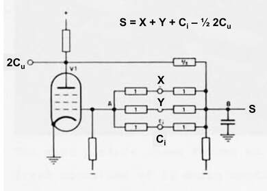
The Kirchhoff-adder basic circuit as used in the PTERA.
|
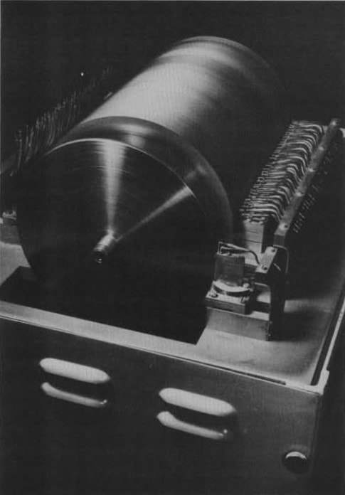
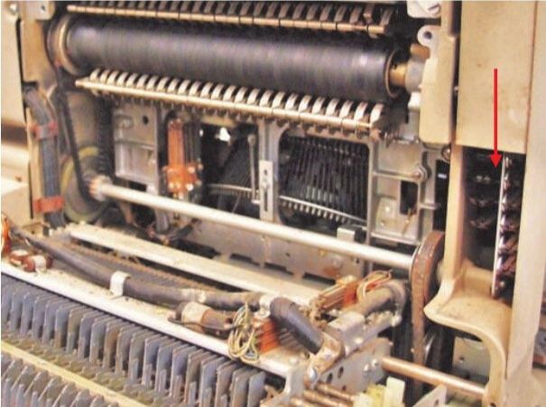
The PTERA drum memory with the cover removed. The 32 parallel read heads are clearly visible. The black disk in front generated the system clock pulses of 38kHz. [OBJ]
|
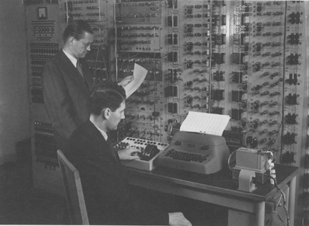
Leen Kosten, standing left, and Willem van der Poel, seated, in front of the PTERA computer in 1953, still on the 2nd floor of an old house behind the Kortenaerkade. On the desk right the punched tape input reader, centrally the electric type writer output device.
The PTERA in use.
|
Because the PTERA development had been under much time pressure not much attention had been paid to reliability and ease of maintenance. Like all valve-based computers reliability of the valves was problematic, and even more so for the electro-mechanical relays, and van der Poel estimates that on average 50% of the time was spent on repair and maintenance. At the same time the machine was intensively used, according department head Leen Kosten up to 14,5 hours per day. Using the machine was deemed to be very simple, and users received a half hour instruction into its use. The PTERA was used almost continuously up to 1958, when it was salvaged to make room for the next machine.
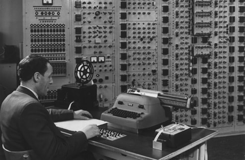
Frontal view of the full PTERA computer, now in the new DNL in Leidschendam. Note that, compared to the left picture, the second and third rack from the left have been modified/upgraded, likely by replacing relay-based modules by valve-based modules.
|
Philips Research computer developments up to 1960
Philips, at least during the 1950s, followed a quite different path in computing than many other companies and institutes. During the early 1950s also Philips management under president Frits Philips was confronted with the question if computers would be relevant for the company, and if yes how. Although there were undoubtedly supporters of the idea, the general conclusion was not to pursue this path. The main argument, most vocally expressed by Herre Rinia, head of the Philips Research sector Systems and Electronics, was that computers were big and very expensive, and therefore mainly used in major scientific or defence institutes. This was seen as a too small market, and the energies of Philips were required for the roll-out of television. However, in the best Natuurkundig Laboratorium tradition a few people were asked "to look into this".
|
But another reason for the Philips passivity on the systems development was the focus on components. During the early fifties Philips Elektronenbuizen (Electronic Valves) Division was establishing itself as one of the leaders in radio valves, and the internal view was that, except for radio and television, it was more profitable to be the leading component supplier than the set or systems manufacturer. This was also seen to hold for the emerging computers, where IBM quickly established itself as the leading player. As mentioned in the earlier section, the amount of valves in computers was enormous, typically 2000-5000 in the IBM machines, making it a very attractive growth market for the valve division. Philips therefore tried hard to get a formal partnership with IBM, based on an agreement of mutual exclusivity: IBM was to purchase as much as possible Philips components for its computers (especially valves), while Philips would not compete with IBM and abstain from computer development. The agreement was signed May 1st, 1956, and was actively implemented till the end of the decade. The effect of this will be seen later.
|
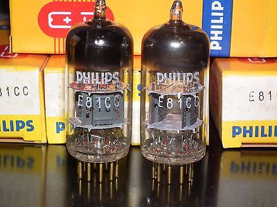
Philips was very successful with its series of special professional valve versions. They used codes like shown here E81CC, as opposed to the consumer dual triode ECC81. Others were the E82CC (ECC82) and E88CC (ECC88). These tubes were selected for tighter specifications and longer life. They were also available, as shown, as matched pairs.
|
In the meantime, by 1953, the Philips Research NatLab group had decided to develop its own computer. Given the timing, it is not surprising that many concepts were taken over from the ARRA II and PTERA, especially the latter. The machine was baptised Philips' Experimentele Tweetallige Elektronische Rekenmachine (PETER, for Philips' Experimental Binary Electronic Computer). The machine was deemed ready in 1956 and used for mathematical computations for the different NatLab activities, like the calculations on the new microwave magnetrons and cyclotron. It also used a magnetic drum memory (64 tracks of 16 24-bit words), 20-bit data words, values between -1 and +1, and a 16-bit instruction format, with the first 10 bits defining the address and four bits specifying the instruction. The machine thus had 16 different instructions, and like the PTERA three registers: the A (accumulator), S (summation) and M (memory) registers. A and S could be serialised for multiplication, while the contents of A and M could be added in a parallel operation. Like the PTERA, use was considered to be very simple and users received a 20-minute instruction. Also the PETER suffered from reliability issues, mostly cold joints of the germanium diodes, and required quite some maintenance. It operated till the end of 1959 but there are no known pictures of the machine.
The PTT-STANTEC ZEBRA, 1958
|
Where the UvA Mathematisch Centrum was struggling with the handover of its next-generation concept to the new company Electrologica and Philips was not formally interested in computers, the Dutch PTT group of Kosten and van der Poel steamed ahead. The Centraal Laboratorium of the PTT where they belonged to had in the meantime moved from the The Hague city centre to a brand new laboratory in Leidschendam, a few kilometres to the north. The new director was dr.ir. van Duuren, the former head of the Radio Laboratory and thus the department head of my father who was working there since 1949. The Radio Laboratorium was taken over by jonkheer van der Wijck, who had worked on equipment for the early radio telegraph links with the Dutch East Indies. Leen Kosten remained the head of the Mathematics Department, which had grown to just eleven people. The new building was officially inaugurated May 17, 1955 and then re-named Dr Neher Laboratorium (DNL) in honour of the former PTT director that had pushed hard for the establishment of the laboratory and its new building.
|
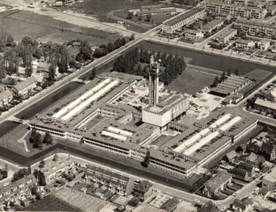
The new PTT Centraal Laboratorium in Leidschendam with its characteristic tower. It was officially opened 17 May, 1955 and became from then on the Dr Neher Laboratorium (DNL).
|
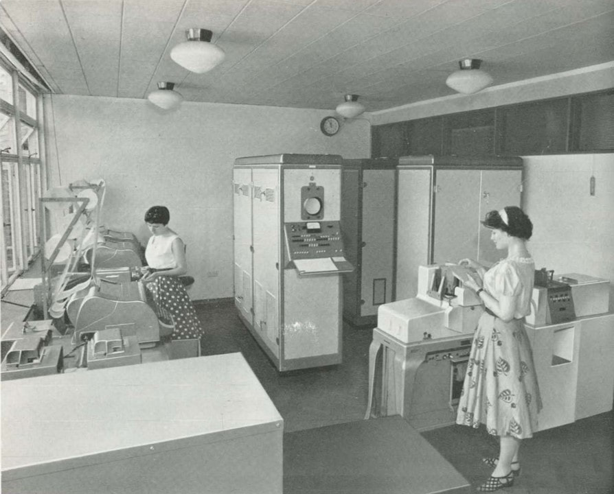
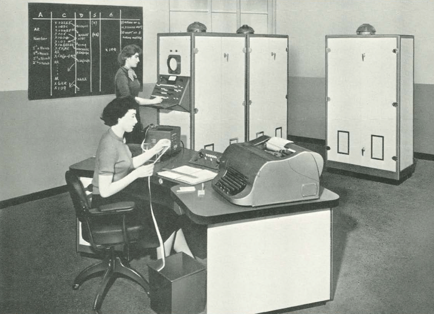
Willem van der Poel based his design of the next generation computer on its two predecessor creations, of course the PTERA but even more so the ZERO. From the latter he re-used the concept of instructions that were selected by a single fixed bit from the instruction word. Fifteen instruction bits were used for this, while five more referring to fast access registers 25 to 30 for input-output operations. Another 18 bits specified the magnetic drum memory address, bsed on 256 tracks (8 bits) of 32 words (5 bits). The total word and instruction length was thus 15+5+8+5=33 bits. The concept was called Zeer Eenvoudige Binaire Reken Automaat (ZEBRA, Very Simple Binary Computing Machine). Like the ZERO the ZEBRA did not perform pure multiplications or divisions, but these were done through repeated addition or subtraction. It used similar registers A (accumulator), B (for long words in multiplications and divisions), C (control) and D (the address counter that contained the address of the next instruction). All processing was serial for simplicity and speed, and the clock frequency 128kHz.
Interestingly, unlike the PTERA, the PTT decided not to build the ZEBRA itself, but instead approached several external parties in the Netherlands for that role. This was 1955. Again Philips declined, although its subsidiary Nederlandse Seintoestellenfabriek (NSF, the Dutch Telegraph Equipment Factory in Huizen, part of Philips Telecommunicatie Industrie, PTI) was very interested, but forced to withdraw from the discussions by Eindhoven headquarters. In the end the PTT DNL management was brought into contact with the Bell Telephone Company in Antwerpen, Belgium, and its subsidiary Standard Telephones and Cables Ltd (STC or STANTEC) in London. This company was impressed by the power of van der Poel's architecture and willing to take on the engineering challenge. A contract was signed in 1956 and development started. Only two years later, in April 1958, the first ZEBRA was installed in the Dr Neher Laboratory Mathematics Department for use by van der Poel and his team. (As a side node, the team then immediately and "with lots of pleasure" demolished the PTERA, apparently exasperated by the support effort and limitations of that not-so-reliable machine. Nothing remains of the PTERA).
Interestingly, unlike the PTERA, the PTT decided not to build the ZEBRA itself, but instead approached several external parties in the Netherlands for that role. This was 1955. Again Philips declined, although its subsidiary Nederlandse Seintoestellenfabriek (NSF, the Dutch Telegraph Equipment Factory in Huizen, part of Philips Telecommunicatie Industrie, PTI) was very interested, but forced to withdraw from the discussions by Eindhoven headquarters. In the end the PTT DNL management was brought into contact with the Bell Telephone Company in Antwerpen, Belgium, and its subsidiary Standard Telephones and Cables Ltd (STC or STANTEC) in London. This company was impressed by the power of van der Poel's architecture and willing to take on the engineering challenge. A contract was signed in 1956 and development started. Only two years later, in April 1958, the first ZEBRA was installed in the Dr Neher Laboratory Mathematics Department for use by van der Poel and his team. (As a side node, the team then immediately and "with lots of pleasure" demolished the PTERA, apparently exasperated by the support effort and limitations of that not-so-reliable machine. Nothing remains of the PTERA).
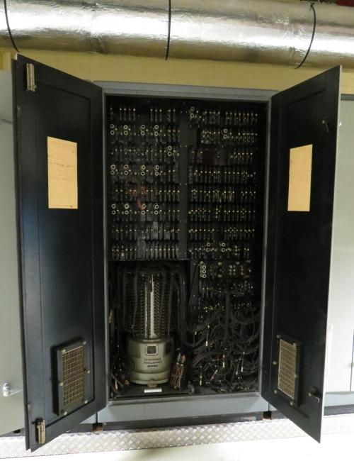
Interior view of the main ZEBRA cabinet, housing the improved drum memory. Unique for these first generation computers, a ZEBRA survived the times and is conserved in the Historic Collection of the EWI department of the Technical University Delft. [TUD]
The STANTEC-ZEBRA, as it was called, was a well-engineered equipment, which turned out to be reliable. This included the upgraded 256-track drum memory, which had a word access time of 312us according the company leaflet. This were also the execution times of an addition and subtraction. Multiplication took 11ms and division 35ms. On the engineering side STC introduced several improvements compared to the ZEBRA, especially the use of plug-in standard modules. These were not as large as the IBM 650 modules, containing up to three dual triodes two flip-flop or other logic circuits. Another innovation was the wire-wound backplane, improving reliability. The ZEBRA also introduced the first transistors, although this was only possible for roughly half of the functionality, and many valves remained.
|
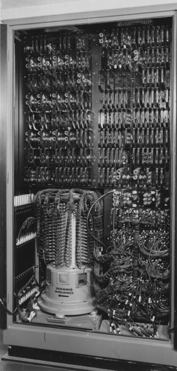
A contemporary picture of the same section. The standard plug-in modules are visible. [DBNL]
Close-up of the new drum memory. The read and write heads of the 256 tracks were spread across the circumference of the drum. As visible the increased number of tracks led to a much larger number of cable connections. [STANTEC-ZEBRA leaflet, 1960]
|
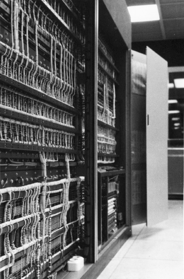
Picture of the ZEBRA backplane using wire-wound technology. [STANTEC-ZEBRA lefalet]
|
As intended by van der Poel the ZEBRA was a very flexible machine, due to the limited yet very basic machine instructions. A programmer thus had a lot of freedom to optimize programs, assuming he made optimal use of the machine code. This had, however, two implications. The first was that less experienced programmers could not easily achieve optimum performance using the so-called NORMAL CODE. The ZEBRA therefore also offered a SIMPLE CODE, essentially a number of code lines grouped for optimal execution of a higher-level instruction. It used an interpreter to translate the SIMPLE CODE instruction into a set of optimized NORMAL CODE. The price for this programming simplification was a speed reduction of roughly two. Based on this concept, and the fact that the ZEBRA machines were identical across users, over the years also higher-level programming languages like LISP and ALGOL could run on the ZEBRA. For this a substantial international user group formed over the years, and the ZEBRA had a core of enthusiastic supporters.
|
|
The other group of ZEBRA programmers - and in fact the "real" programmers - had to make do with the specifics of the machine and its internal data handling. Due to the slow drum memory access significant speed increase could be gained by using short registers for storing intermediate results, and then executing a series of micro-instructions in one go. This approach was baptized "under water programming" and required a very detailed knowledge of the machine operation. Another complication was that following these micro-instructions deep inside the machine was difficult if not impossible, and an additional interpretive tracer was built by the group of van der Poel. The way of working to achieve these type of approaches was called "trickology".
Due to all these characteristics the STANTEC-ZEBRA saw a considerable success in the market. After the first one was installed at the PTT-DNL in April 1958, STC sold in total 55 machines in the 3-4 years following. Of these nine were sold in the Netherlands, mostly to universities, national scientific institutes and one to the Koninklijke Marine (Netherlands Royal Navy). Probably halfway its life, so around 1960, the ZEBRA received an upgrade and became all-transistorized. Reliability proved indeed to be excellent, and for example the PTT ZEBRA was used almost continuously till 1967 when it was replaced by an Electrologica X8. In contrast to the PTERA, which was as mentioned demolished, the ZEBRA went to the electronics department of the Technical University Delft, where it is preserved in the historical study collection. All-in all, the PTT/STANTEC-ZEBRA was a very nice success, especially seen through the eyes of the Dutch PTT and Dr Neher Laboratorium. It was the first Dutch-born computer of which more than 2 machines were made, and the first to see real commercial success and a tight user group. Willem van der Poel rightfully achieved international fame based on his creation. We'll see him back in a section further down. |
Van der Poel next to the ZEBRA. On this console on the side of the machine the content of selected registers could be displayed on the scope display.
|
The ZEBRA as installed at a UK Aircraft Reseaerch Establishment. [STANTEC-ZEBRA leaflet]
|
Another ZEBRA installation. On this picture a typical vander Poel-style programming flow is written on the black board.
|
The Philips PASCAL and STEVIN, 1959
|
Around this time, the end of the 1950s, both the UvA Mathematisch Centrum and the PTT contact Philips to probe its interest for taking over the concepts of their ARRA II (and successor) and PTERA (and successor ZEBRA). But Philips declined all offers, referring to their IBM-agreement and di not start any commercial computer developments. Internally, however, pressure was building up from the fast Rekencentrum (Computing Centre) that was responsible for all administrative data handling within the company. On the one hand there was the demand for data availability and analysis of the rapidly expanding company, both for the financial and personnel administration. This work was done using punched cards, but the amount of these cards was exploding and the Rekencentrum deemed it essential to move to electronic automation through the use of computers. However, at that time, roughly 1957, they considered none of the commercially available computers to be good enough and/or affordable. (Which is somehow surprising, one would expect that given the strategic supply relation of Philips and IBM it should have been possible to purchase an IBM machine at a "friends" price. And indeed, in 1959 two IBM 650s were installed in the Rekencentrum).
The NatLab Research organisation therefore decided to develop a next generation, much more robust and reliable successor of the PETER. Work started in 1957 and the machine, baptized PASCAL for Philips Akelig Snelle Calculator (Philips Horribly Fast Computer, later the acronym was anglicized to mean Philips Automatic Sequence Calculator) was ready in 1959. |
The wiring backplane of the PASCAL, with opened cabinet doors. [Eindhoven in Beeld]
|
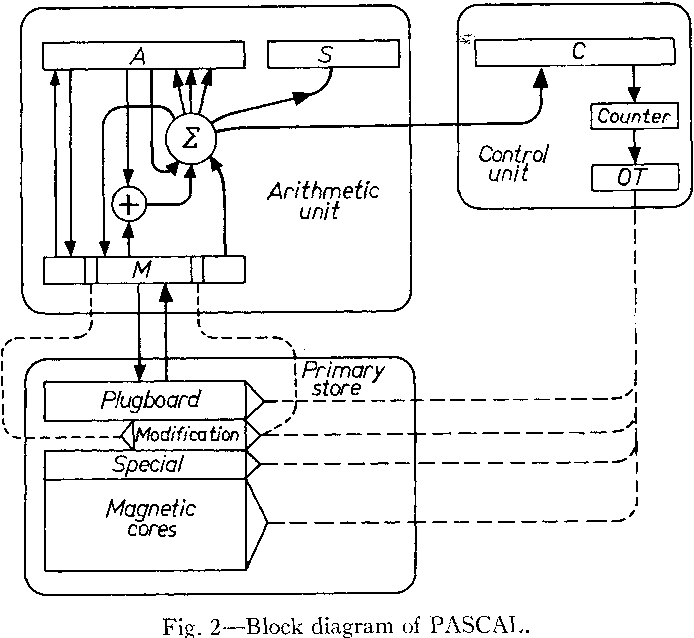
High level block diagram of the PASCAL, showing the four main registers A, S, C and M. The plugboard allowed manual insertion of instructions, which also allowed manual modification of an instruction in case a program was halted. [From a 1961 IRE publication on the PASCAL]
|
At this time, before the standardisation into bytes a few years down the road, the trend was to use ever wider word lengths. Where the PETER had used 24-bit words, the PTERA 30, and ZEBRA 33, the PASCAL moved to 44 bits of which two were parity bits. Fixed point data was represented as a 41-bit word, a floating point number as a 34 -bit fraction plus 8-bit exponential. Two 21-bit instructions fitted within one word, where within an instruction 11 bits defined the address and 10 bits were available for the instruction definition. The core architecture of the PASCAL strongly resembled the ZEBRA, although in contrast a number of operations - like in the PETER - was performed in parallel instead of serial, including the memory access. The instruction set of the PASCAL was also slightly more higher level than the ZEBRA, while it also featured multiple diagnostic registers. Another first of the PASCAL was the use of a magnetic core memory as fast memory. Due to the cost its size had to be limited to 2016 words, so in total 88kb. The magnetic core memory was directly connected to the processor unit, while a separate interface connected to a large drum memory of 16.384 words (possibly 256 tracks of 64 words). The PASCAL was also the first to feature a magnetic tape back-up memory. Although, like the ZEBRA, also the PASCAL introduced the use of transistors, 8000 in total, the machine still used 1200 valves. A plug-in modular approach very similar to the IBM 650 family was used, with eleven valves per module.
|
Front side of the PASCAL showing a standard module being inserted. Each of the four visible blocks contains 25 rows of modules, each with 11 valves. 275 valves per block, the four blocks in total 1100 valves. [Philips]
|
Because the development of the new computer was very much pushed by the Rekencentrum, it was decided that next to the PASCAL a second machine would be built specifically for the administrative applications. This machine, the Snel Tel- en Vermenigvuldig Instrument (STEVIN, Fast Counting and Multiplying Instrument), was identical to the PASCAL apart from its IO.
The PASCAL input machines, next to the classical punched tape reader, were a punched card reader and a magnetic tape reader, in total 16 input devices could be connected. Outputs were tape puncher, card puncher, line printer and magnetic tape. The STEVIN did not use punched tape IOs but instead received a high-speed printer (which still required magnetic tape as an intermediate step). Some of these input devices, like the punched card reader, were buffered with dedicated magnetic core memories, allowing the computer to run without interruption waiting for slow input data. The PASCAL/STEVIN were developed by a team of 7 Philips Research engineers led by Heijn and Selman, with obviously much support from the NatLab workshops. While the PASCAL became operational in 1959 within the NatLab Research laboratory (still at the Kastanjalaan on the Strijp-S complex), it took all year 1960 to debug and test it, as well as its twin STEVIN. In the course of the same year both machines were moved to the Rekencentrum in Eindhoven, where they were officially inaugurated March 21, 1961. |
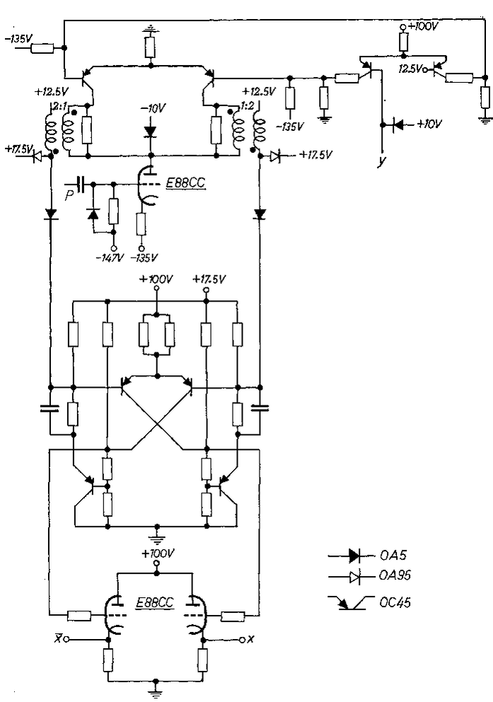
The PASCAL used so-called hybrid electronics, a combination of valves (E88CC at the bottom of the diagram and one further up) and transistors (OC45 PNPs).
|
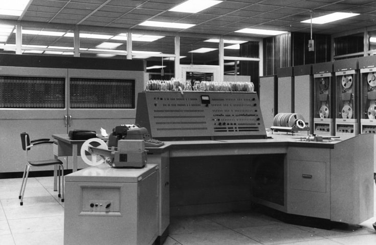
The operator console of the PASCAL/STEVIN installed in the Philips Rekencentrum in Eindhoven. This console allowed manual setting of certain registers, start and stop of the program execution and if necessary manual modification of an instruction. [Eindhoven in Beeld]
|
A complete PASCAL or STEVIN system as installed in the Philips Rekencentrum. In the centre the main computer, on the right five Ampex magnetic tape drives, and on the left several IO devices. [Philips]
|
Although the PASCAL/STEVIN was a quite powerful machine, it was not intended as a commercial product, but instead a purely internally focussed solution for the organisational challenges within Philips: the growing complexity of scientific calculations and simulations, and the need for rapidly increasing data processing speed in the administrative and financial domain. Although by this time (196o-1961) it became clear that IBM had no longer the intention to stay out of component manufacturing, releasing Philips from the obligation to stay out of computer manufacturing, there was still no clear strategy as to the entrance in this domain. The PASCAL showed that technically there were no real limitations, as so often given the strong technology basis of Philips, the question was whether a solid business case could be developed.
In the meantime the PASCAL and STEVIN, essentially the last generation computer still largely based on valves, operated for many years in the Rekencentrum, supporting both the scientific and administrative functions within the company. The PASCAL moved one more time, to the new Philips Computer Industry group in Apeldoorn. Both machines were probably replaced around 1965-66 by Electrologica X8 machines, although they were not removed until 1972. Like the ZEBRA, at least the PASCAL machine was saved and transferred to the same EWI Study Collection at the TU Delft department of electronics.
In the meantime the PASCAL and STEVIN, essentially the last generation computer still largely based on valves, operated for many years in the Rekencentrum, supporting both the scientific and administrative functions within the company. The PASCAL moved one more time, to the new Philips Computer Industry group in Apeldoorn. Both machines were probably replaced around 1965-66 by Electrologica X8 machines, although they were not removed until 1972. Like the ZEBRA, at least the PASCAL machine was saved and transferred to the same EWI Study Collection at the TU Delft department of electronics.
The PASCAL computer can still be seen in the TU Delft EWI Study Collection. The valves are predominantly E88CC professional versions of the ECC88 dual triode. [TUD]
Philips transistor development, 1954-1960
The early history of transistor development up to 1954 has been described in detail as part of the early TV history and tuner history. That ended with the commercial launch of the first transistor, the OC70 and OC71, essentially binned (preselected) versions of the same device due to the large spread in parameters of the first production process. Later, when production quality improved. a third version was released as OC75 with a higher guaranteed gain. The OC70-family transistors were encapsulated in the characteristic glass bulb, which was painted black to avoid light influences. (By removing the black paint the device was used as photo-transistor OCP70). The early PNP transistors still had very mediocre performance and did not operate at voltages we are used today for small-signal design. Typical collector-emitter voltages were 6-10V, in which case the collector current was typically 10mA and power dissipation around 250mW. Due to the still very low current gain (30 for the OC70) the base current could be as high as 6-7mA, and they showed a large temperature dependence. These first transistors therefore had as main advantage their small size and, compared to a valve, much smaller power consumption. First applications were therefore especially size-constrained uses like hearing aids. In the next two years some larger transistors were released (OC72, 76, 77) that supported higher currents and could be used in power drivers. But despite the initially poor performance, the transistor remained a major breakthrough in electronics design!
|
First two pages of a Philips leaflet, probably from around 1956, promoting the use of the OC70 and OC71 transistors. On the right page the first two applications: hearing aids and record player pick-up elements. [Wolf Schieber]
|
The initial problems with volume production of these transistors should not be underestimated. In 1954 Elektronenbuizen had still only two types of transistors in production, mostly in Heerlen in Dutch Limburg, the first generation point contact transistors (OC50 and 51) were produced at 350 pieces per week with 30% yield, the first planar PNP transistors OC10 and 11 hardly ran better at 250 pieces per week at 10% yield. Production of the point contact OC50/51 was quickly stopped, after some 10.000 pieces. The same happened to the OC10/11/12, which were all replaced by the first real production types OC70 and OC71. In 1954 the new Nijmegen semiconductor fab was opened, led by ir. Jan van der Spek who had been responsible for transistor development within the HIG. From then on production quickly improved, although the whole organisation had to go through a steep learning curve with respect to process automation and control, and at least initially much production work was still done by hand.
|
Obviously, development of new and improved transistors had started in the meantime. The next family was the OC40, which was introduced 1956-57. The first two types focussed on one of the main Philips applications, radio broadcast receivers. The OC44 was an AM mixer transistor, the OC45 an IF amplifier. These transistors were almost immediately used by many companies in portable radios, which were usually not 100% transistorised, often still using one or two D90 series valves. But for this story here, the most interesting types are the OC46 and OC47, two binned versions of the same transistor, that were optimised for digital applications. [Binning means that the transistors were measured for a target specification. Those that fell within that spec ended up in bin 1. Those that failed the target range but still met the specification of a next lower range came into bin 2. Etcetera. The transistors from each bin received a different type number and commercial data sheet). The OC47, the better one of the two, had a much improved voltage gain of typically 100, and operated at much improved voltage and current settings, typically 5V and 7,5mA. A last innovation, at the closing of the decade, was the NPN germanium transistor OC139. The OC139 NPN and OC47 PNP were very compatible and could thus be used in push-pull arrangements, greatly enhancing circuit design freedom.
With the OC47 and OC139 as standard PNP and NPN transistors, the OC77 as power driver, and OA50, OA85 and OA95 as general purpose diodes with the OA200 power diode, all components were now available for transistorized digital design. As a last remark it is interesting that the OC139/140 were amongst the very last transistors coded OC. From 1960 a new international semiconductor naming convention was introduced, with general purpose germanium diodes now coded AC. The existing types were often re-coded for the new naming, for example the OC70 becoming the AC125. |
Philips OC transistors, still not cheap and mostly not used in large numbers yet, were supplied in boxes very similar to those for the valves. [Radiomuseum.org]
|
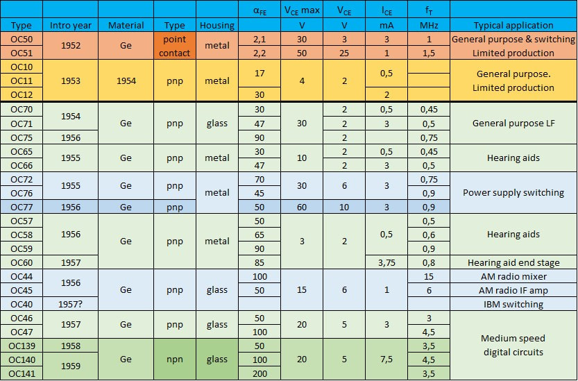
Overview of the first three generations germanium transistors produced by Philips and its sub-brands Valvo, Mullard, and La Radiotechnique. The first two families above the black bar were only produced at a low level, and never became mature. The OC70/71 were the first really mass-produced transistors.
Transistor application development at Philips CAB, 1952-1956
As we've seen in the stories on the television and TV tuner developments, the Radiobuizen Lab (RBL, Radio valve lab) of the HIG Elektronenbuizen (product division electron valves) was a very important player in the development of new valves that were optimized for the Philips applications. The RBL existed since 1946 and consisted of two groups, one for consumer applications and another one for professional applications. One of the leading members was dr. Bert Dammers, who joined in 1946 and turned out to be a genius in the field of new valve applications for television and radio applications. In this time my father was (one of) his assistants, working on the EQ40 and the new television sets.
Bert Dammers, head of the CAB, giving a speech during the farewell party of one of the colleagues. [Wolf Schieber]
|
Dammers was the head of the RBL Consumer group, while ir. Klaas Rodenhuis led the Professional valve group. In this period the founder of the RBL, ir. Gerrit Alma, was succeeded by ir. Jan van Vessem, who we have seen as one of the promoters of the development of germanium transistors. It is therefore not strange that the RBL, despite its name, was seriously looking into transistor applications, initially almost certainly the hearing aids. Probably around the end of 1954 both Jan van Vessem (to the semiconductor plant in Nijmegen) and Klaas Rodenhuis (first to the role of head of valve and transistor technology for the HIG Elektronenbuizen under ir. Henk Hazeu, and in 1959 to become the plant manager of the Hamburg Valvo valve factory) moved out to their next career opportunities, while Bert Dammers took over the RBL. The name of the lab at this time changed to Centraal Applicatielab Buizen (CAB, Central application lab valves) and during the second half of the decade was extended to Centraal Applicatielab Buizen en Transistoren. Despite all these formal name changes, however, the organisation was generally known as the "Dammers-lab". The lab was located in the Witte Dame (White lady) building on the Emmasingel in Eindhoven, fourth flour (EF4, with section of the Professional group working on UHF transmitter tubes on the EF6 top floor), but early 1956 the lab moved to the first floor (EF1). Dammers had his office in the centre of the floor, with left and right two open spaces with the Consumer and Professional group engineers.
|
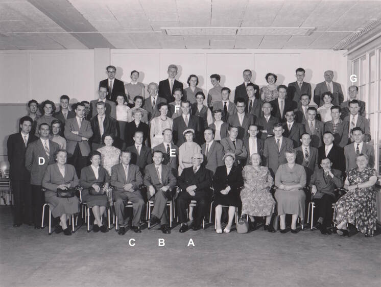
A mysterious yet very interesting picture of the CAB, with some 36 employees and many of their wifes. No formal details are known, but my interpretation is this was at the occasion of the 10 year jubilee of the Radiobuizenlab/CAB, which times it as 1956. That would mean that on the front row A-B-C are its three (former) directors: from right Gerrit Alma (1946 to about 1952), Jan van Vessem (1952-1956) and Bert Dammers (1956-1968). Klaas Rodenhuis (D) already no longer worked in the lab, but as former group leader for Professional applications joined the celebrations. E-G are three of the TRANSDECO team engineers: Jan scholten (E), Hans Tierates (F) and Wim van Kempen (G). Wolf Schieber, the fourth team member who gave me the picture is himself not present. [Wolf Schieber]
|
From the moment the transistor invention by Bell Labs was announced the Philips strategic management had been discussing transistors, and it was concluded this was a breakthrough new technology where Philips absolutely needed be involved. On the one hand this had a defensive element, to safeguard the important electron valve business or at least guarantee a smooth switch-over, but there was definitely also the vision that the transistor opened new ways impossible with valves. Next to the technology development that has been described, also many application discussions took place. From 1952 several discussion groups on transistor applications were created, regularly reporting to the Philips Board of Management. In these ir. Henk Hazeu, Technical Director of the HIG Elektronenbuizen was a leading player, while Bert Dammers of the RBL/CAB was regularly invited to present his views. This shows that this organisation was actively working on the evaluation of transistors, although the conclusion was mostly that, given the still poor performance of the OC50/51 point contact transistors and OC10/11/12 first planar transistors, application was not evident. Nevertheless, within the company there was a clear view on which applications were expected to be most relevant from a transistor point of view. In order of business opportunity they were listed as follows:
|
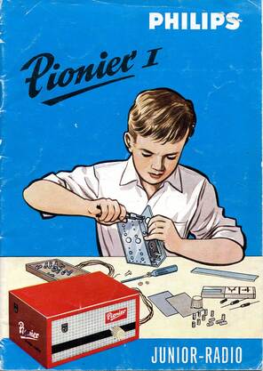
Although not important a s a volume market, Philips was very active in promoting the transistor for hobby applications. Already in 1957/58 the by now famous Pionier I self-building radio box was launched and saw a lot of success. It contained OC13 and OC14 transistors, which were in essence OC71 and OC72 production fall-off (so probably transistors with a forward current gain below 20).
|
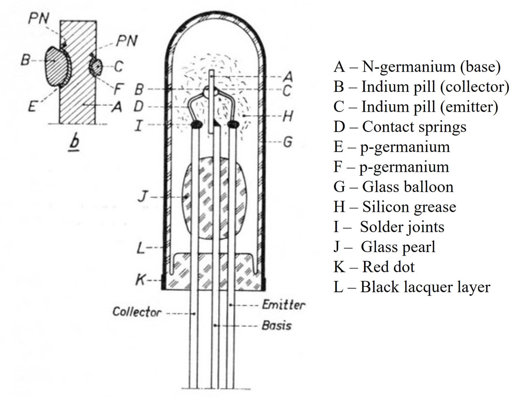
Cross section of an OC alloy diffusion germanium transistors. On the left the die cross section, on the right the encapsulation. [D.J.W. Sjobbema, Schakelen met Transistoren, Philips Technische Blibliotheek, 1959]
|
Of this list the hearing aids business was the first to really start using transistors as soon as the OC70 and OC71 were released, for obvious reasons of miniaturization. It is very likely that the CAB supported them with reference designs, although there is no hard proof of that. in any case Philips Hearing Aids was to remain a leading (European) player until, like so many businesses, being sold in the disastrous Boonstra presidency in 1999. (Today Philips-branded hearing aids are still being sold, confirming the solid reputation this business had). Radios were also quick to adopt transistors for portable devices, although initially often still in combination with one or two valves. Television was to take another 8-1o years before seeing serious transistor use. To the frustration of the higher management both professional applications in instrumentation (Philips Industriële Toepassingen, PIT, Philips industrial applications) and telecommunication (Philips Telecommunicatie Industrie, PTI) were very slow in looking into transistor applications. In the end Philips remained very strongly a component supplier, and the HIG Elektronenbuizen sold 80% of its transistors and diodes to non-Philips customers. It is therefore no surprise that the primary application lab of this HIG, the Radiobuizenlab /Centraal Applicatielab Buizen was one of the most active centres looking into transistor applications. And it is therefore also obvious they looked first into the big external application markets for valves: computers and telephone equipment.
|
TRANSDECO, the first transistor-only computer in Europe, 1958
In 1956, with the OC47 transistor optimized for switching applications was coming available internally on sample basis, the HIG Elektronenbuizen management (Henk Hazeu as HIG technical director, Klaas Rodenhuis and Bert Dammers as managers of the CAB) decided that a compelling application demonstration of these transistors in a typical computing application was required: a fully transistorized computer for small business machine applications. In 1956 a small team was created within the CAB of Dammers: ir Jan Scholten, ing. Wolf Schieber and technician Hans Tierates. Jan Scholten had recently graduated from the TH Delft, and regularly went back there to get up to date with the latest computer concept developments. Wolf Schieber had joined Philips fresh from technical college in Wien, Austria, as part of a Philips program to hire young engineers from abroad. Together with six fellow Austrians they arrived in Eindhoven in 1955, Schieber joining the UHF-team in the professional group in the CAB. Hans Tierates was an electronic engineer who joined Philips RBL/CAB also in 1955. [As an anecdote, he was also intended to join the same UHF-team, but on the mornng he reported for work no management of that team was available, and he ended up in the digital team]. Obviously, none of the three had any practical experience in computers. They nevertheless set to work quickly, where Scholten dived into the computer architecture, Schieber was responsible for all electronic functional design, and Tierates did all the assembly and especially testing. Of course they received much support from the workshops, while over time another three support staff were added for documentation, assembly, etcetera.
ir Jan Scholten of the CAB, the principal architect and project leader of the TRANSDECO computer. [via Wolf Schieber]
|
ing. Wolf Schieber, the Austrian engineer responsible for all electronic design of the TRANSDECO, in his office in the Witte Dame on the Emmasingel. [Wolf Schieber]
|
|
The computer they designed, baptized TRANSDECO for TRANSistor DEcimal COmputer, was 100% transistorized. In 1956 using the then available OC71 general purpose transistor, the OC77 power output driver, and a handful of OC36 power transistors a first analysis of critical building blocks was made. The promising results of these experiments were used to convince the CAB management to start the real prototyping of a small digital computer for business applications. The real design now switched to the new OC47 switching transistor. It also exclusively used a ring core memory, no longer a drum. Two ring core memories were used, one for data and instructions, one for storing the micro instructions. The first memory was a standard module produced by Philips, most likely still in the HIG ICOMA labs in Eindhoven, but a precursor of the volume production of magnetic core memories at Valkenswaard, south of Eindhoven, up to 1972. The micro instruction memory, however, had the code woven permanently into the memory fabric. This was done in-house within the CAB, by the team itself! The TRANSDECO did not use a spectacular new architecture and was, based on the accessible information, of a state-of-the-art concept but then of course fully transistorised! The details of the TRANSDECO will be explained on a a separate sub-page, here only the main features will be presented.
|
The core of the Transdeco was the accumulator, based on decimal (0 to 9) counters. These were made from four standard flip-flop bi-stable elements (top row). Because four binary of these flip-flops in series act as a counter to 16, a trick was applied. When the counter came to 8 (output c of FF4 going high, output c' going low) both FF2 and FF3 received an extra count pulse, such that at the next input pulse the counter state 9 became equal to 1-1-1-1 and the 10th input would reset to zero. After going through a full cycle a carry pulse was generated for the next higher decimal counter.
Hand wiring of the micro instructions into a core memory unit. Although the ring cores in the instruction memory were bigger at about 5mm diameter than those in a standard data memory, they were still very small with up to 16 wires passing through an individual ring. [Wolf Schieber]
|
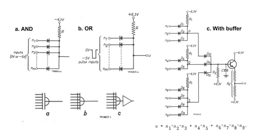
The basic logic AND and OR circuits as used. On the right an example of an OR (Do-D1-D2) of three AND inputs, with buffer stage.
For the basic AND and OR logic elements mainly diodes (OA79) were used, see the diagrams on the left, with when required for restoring pulse shapes or reducing the load on a next stage, an emitter follower buffer stage. As shown all circuitry was constructed from discrete elements, soldered onto Printed Circuit Boards (PCB). These PCBs, all of the same size and 116 in total, were mounted into four rows of a standard rack. The top row occupied the accumulator and IOs, the entire second row the control circuitry, the third row the instruction and number memories matrix and itsaccess control, and the bottom row the power supply and the sub-routine matrix, instruction decoder and selection circuitry.
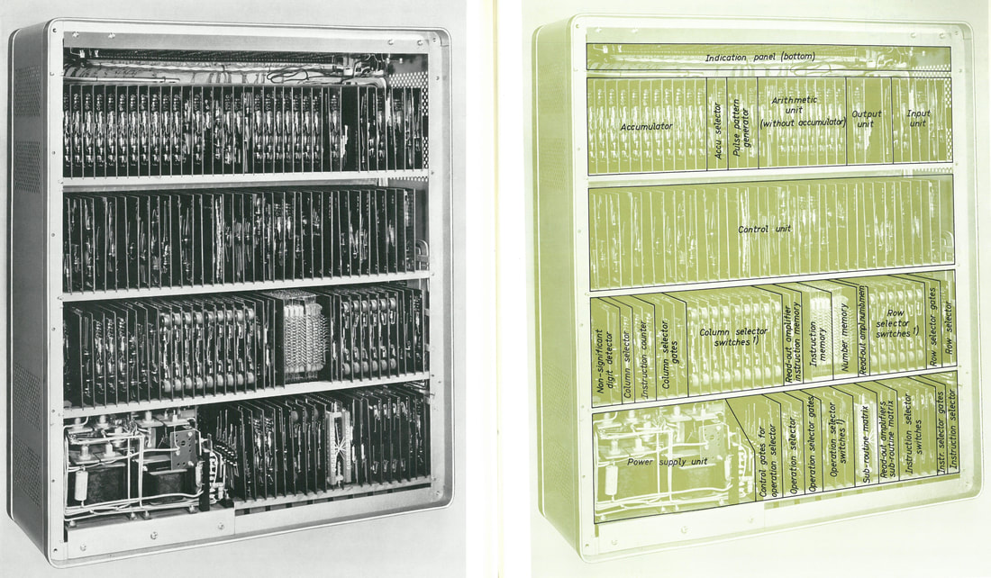
The TRANSDECO as assembled (left) and the functions illustrated on the right. All technical illustrations in this section are from the booklet Philips Computer Circuitry Considerations, 1959.
|
Programming and entering numbers into the TRANSDECO was via a small control panel, while output was printed using an IBM electric type writer. The TRANSDECO was, especially for the time, an extremely compact machine, measuring just 67x58x23cm, an order smaller than any of the then standard computers like the PTT/STANTEC ZEBRA, Philips Research PASCAL and even smaller than the contemporary IBM1400 and PDP-1 computers. dr. Bert Dammers, and his bosses Rodenhuis and Hazeu, were very content with the result, and the device was demonstrated to multiple "high visitors", including Heinz Nixdorf and Max Grundig, both important German Philips customers, and many more like Remington Rand and Ferranti Electronics.
Like all CAB designs, also the TRANSDECO was not developed as a product prototype, but as what we would call today a reference design or demonstrator. However, where most of the concepts demonstrated by the Dammers-lab for radio and television usually were taken over and implemented in new products by the HIG Apparaten, for the TRANSDECO there was no internal system customer. Philips was still not active in computers, and he IBM agreement had only been signed two years earlier. The spin-off of the project was therefore entirely in the domain of the components used, as had been the primary intention at the start. Based on the TRANSDECO, a very detailed booklet was published jointly by the HIG Electron Tubes (to which the CAB belonged) and the HIG Industrial Components and Materials (ICOMA) "Philips Computer Circuitry Considerations" which contained a detailed description of all TRANSDECO concepts and circuits. It is the source of all technical details in this section. It also contained a few circuits, mainly around the matrix memory, using the first OC139 planar NPN transistor. 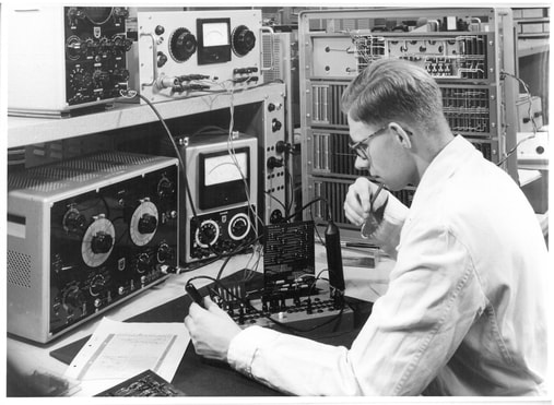
CAB employee and team member Hans Tierates measuring one of the more than hundred TRANSDECO PCB's. The computer itself is seen standing upside down behind him. [Wolf Schieber]
|
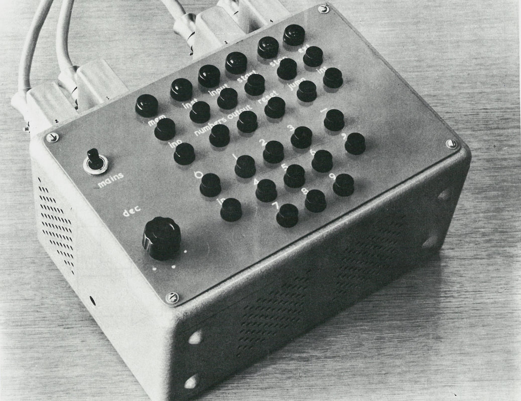
The TRANSDECO input device for both numbers and programs.
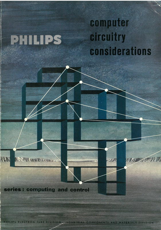
Cover of the Philips booklet (112 pages) from March 1960 Computer Circuitry Considerations. As the front page tells, it was a joint issue by the HIG's Electron Tubes and Industrial Components and Materials (ICOMA). It contained a full and detailed description of the TRANSDECO. [Wolf Schieber]
|
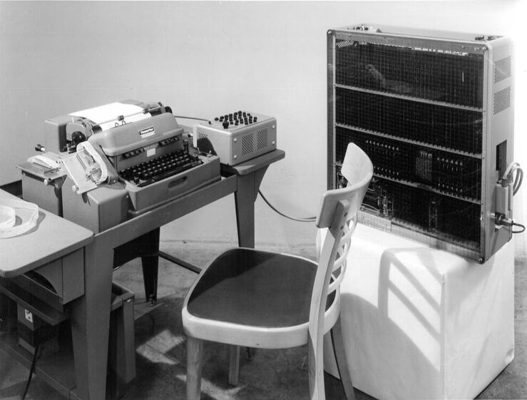
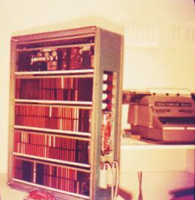
The official Philips CAB TRANSDECO picture, showing the computer on the right, characterized by its 4 rows of PCBs. On the table from the right the manual input device, the Friden Flexowriter electronic typewriter and tape puncher for the output, and a punched tape reader. Note the - even in 1958 - not so high-tech wooden chair, which suggests that the picture is taken in the CAB lab and not in a photo studio. [Wolf Schieber]
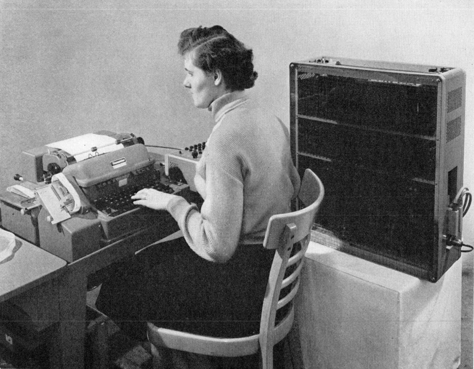
Same set-up, same wooden chair, but now including a lady operator. [From Philips Electron Valves Book IXa, Junction Transistors in Pulse Circuits, 1959]
|
Publications CAB
Much like the television and audio domains, the RBL/CAB remained a source of publications and reference books on the latest topics, in this case digital circuitry. It seems that for this domain there was a special construction, with ir. Pieter Neeteson working as what is called today a scientist in residence. Neeteson was member of the CAB technical staff, but did not participate in projects. Initially he worked on television circuits, publishing part VIIIb in the famous series on Electron Valves "Television Receiver Design, Flywheel Synchronization of Saw-tooth Generators" in 1949. However, after that he switched to the analysis of valves in digital switching applications, or pulse techniques. In 1955 he published "Vacuum Valves in Pulse Technique" as part IX of the mentioned series. This was evidently based on work during the early 1950s, so well before the TRANSDECO project started. Based on this work he wrote a PhD thesis at the TH Delft under professor Tellegen (the inventor of the gyrator), which was published as part X "Analysis of Bi-stable Multivibrator Operation" in 1956. This was again a theoretical work, in no way related to the practical circuit design in the TRANSDECO project.
All books mentioned, which were standard issued in Dutch, English, German, and French, and usually saw multiple editions, were entirely analysing electron valve circuits, but in 1959 now dr. ir. Neeteson published an update of his original part IX, now entirely converted to transistors: part IXa "Junction transistors in pulse circuits". In the preface he makes the following remark: "It is hoped that this method of communicating some experiences in the field of junction transistors in pulse circuits, gained in the Central Application Laboratory of the N.V. Philips´ Gloeilampenfabrieken, Eindhoven, will succeed in its aim of attracting the attention of electronic specialists to this most interesting field of pulse technique and in this way will assist its development upon a sound basis of knowledge. |
Philips Series1 100kHz digital circuit blocks, 1958
How circuit blocks started is not exactly known, but it must have been around 1958 when the TRANSDECO was being completed. It might well be that Dammers and/or Rodenhuis and/or Hazeu saw the benefit of standardized circuit blocks, given the many identical circuit elements used in the TRANSDECO, and talked to the ICOMA management. In any case, the TRANSDECO team was informed one day that ICOMA was planning to develop a series of standard building blocks based on circuits used in the TRANSDECO. Several months later, towards the end of 1957, first samples were received.
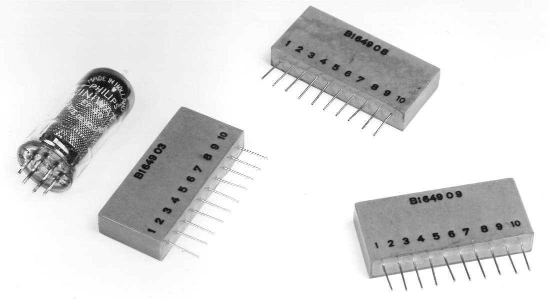
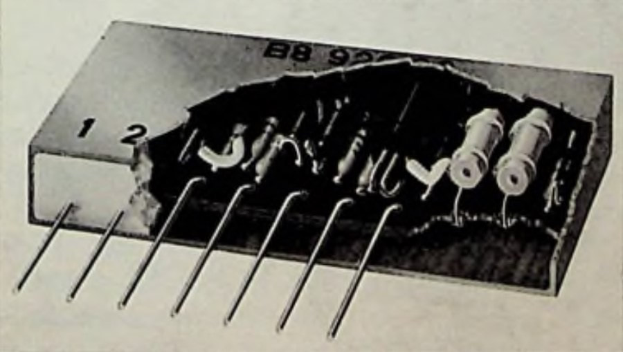
The very first circuit block prototypes from 1958, here seen next to an EF40 pentode for size comparison. Before formal market release the modules were coded B1640 followed by a 2-digit extension specifying the function.
|
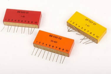
Three slightly maltreated modules as they were commercially released, in their coloured packages. Modules coded B8 XXX YY were developed by ICOMA, modules coded 2P 727 ZZ were developed by the CAB. [Crypto Museum]
|
|
The circuit blocks were essentially packaged printed circuit board (PCB) modules, containing one small PCB with printed copper tracks, and the discrete components mounted and soldered on it. The entire PCB was moulded in epoxy and then inserted in a plastic cover of 54 x 24 x 10mm. On the bottom side ten thin Cu wires stuck out for electrical connections. The modules could be mounted flat on larger PCBs, typically containing 8 of the modules, or could be mounted vertically in small racks, with the wire pins then connected "in the air". Different functional families received a different coloured package. The circuits were identical to those used in the TRANSDECO, sometimes with for example resistor value modifications for more optimal settings and improved life time.
|
Bad, but the only available picture of the insides of a series1 circuit block. [Koroncai, De transistor als schakelaar]
|
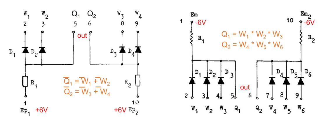
Two of the most simple circuit blocks, the OR (left) and AND (right). Given the limited number of components both could be issues as dual OR and AND, two per package. Note that the OR uses positive supply and is based on inverted logic. The AND uses negative supply but is based on positive logic.
|
The two Flip Flops within the series 1. Internally they are identical, the difference is in which contacts are accessible from the outside. FF1 is the generic function, FF2 is optimized for series connection in counters.
|
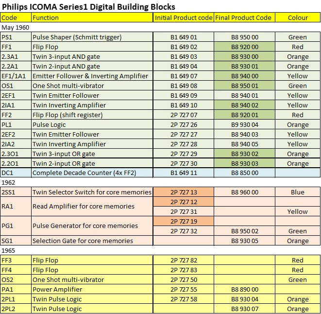
Overview of the ICOMA Series1 Circuit Blocks family. The dates refer to the data books from which the data was retrieved. The highlighted modules were all used in the Mona Lisa CAB project.
One way of interconnecting the Circuit Blocks was shown, with direct pin-to-pin soldering. [Koroncai, de transistor als schakelaar]
The Series1 Circuit Blocks, with their 100kHz maximum clock speed, were very advanced for their time, with many electronic devices operating at substantially lower speeds. Given their price they were used mainly in professional applications, and did so for many years. One example is the signalling system of the London Undergound, where it is said they were still in full use by 2009 on the Victoria Line, without plans for their imminent replacement. A clear indication of their reliability!
|
It seems there were two parallel developments of these modules. As mentioned, the CAB was initially approached by ICOMA with the request to evaluate the prototype modules. These modules received initial product names B1 649 XX, based on the old ICOMA coding system before the 12nc-system was introduced during the mid 1960s. Once taken into production the product code changed to B8 9x0 0Y, where X was a family indicator (logic OR/AND, Flip Flop, etcetera) and Y the individual number within that group. This first series covered nine different modules, that were all used by the CAB in its next project. However, apparently the CAB was not happy with just these nine modules, so they defined another three modules, specifically those around the core memory. These received a different product code, 2P 727 XX, with XX the individual number. In the Mona Lisa report it says "These circuits are own developments of the CAB, which can soon be replaced by circuit blocks 2P 272 19, 13 and 12." These 2P codes were most probably preliminary ("sketch") codes, used before formal release. Remarkably, however, these modules - or their successors with similar code - were taken into production under the sketch product code, since they were listed as such in data sheets. It seems that later 2P products also obtained B8 codes, though. In any case it shows the active involvement of the Dammers-lab in the development of these new modules.
The circuit blocks were announced publicly in 1959, covering the range of models used by the CAB. By the second half of 1960 the range was extended to some 15 types, as shown in the table. Initially they were simply called Circuit Blocks, but when other series of products emerged this first group was listed as "100kHz series". Around 1965 an upgrade series appeared, which was called Series 1 Circuit blocks, but still included some blocks from the 100kHz series. I will therefore collectively refer to these as Series1. They were not cheap, with a price of 1 to 2 GBP. The DC1 full decade counter (which were four FF2 flip flops on a PCB card) cost 12 GBP! The series1 modules operated on +/-6V supply voltages, and up to speeds of 100kHz; the speed of the TRANSDECO. As such they were optimized for digital applications similar to the TRANSDECO technology demonstrator. 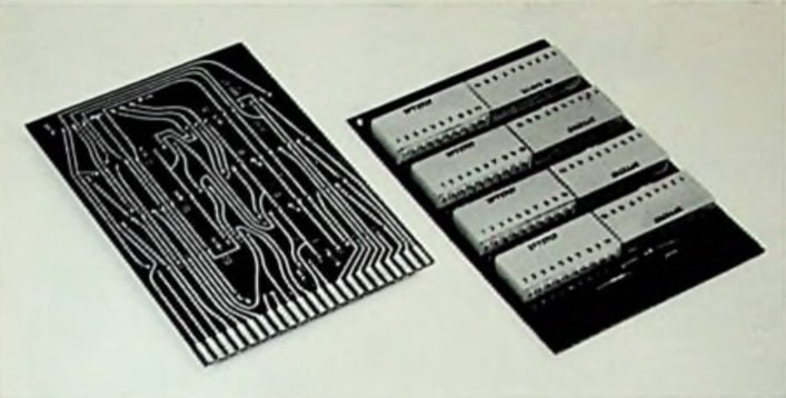
A more advanced way of mounting the Circuit Blocks, on printed circuit boards. [ibid]
|
Philips CAB Mona Lisa, a computer based on Circuit Blocks, 1960
It seems that the TRANSDECO technology demonstrator project was quite successful, given the many demonstrations to customers, the fact that it appeared in quite some Philips books and publications, and the spin-off of digital circuit blocks. Discussions were therefore taking place on the next step, which, not entirely surprising, was to be a successor using as much as possible the new circuit blocks. At the same time a number of concept improvements were to be implemented, based on the experience with the TRANSDECO. When considering a project name the team thought of LISA (Logic in sub-assemblies) but Mr Dammers himself then insisted on the name Mona Lisa.
|
Some of the new features of the Mona Lisa, as compared to the TRANSDECO, were:
|
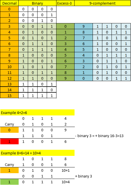
Illustration of the Excess-3 code as used in Mona Lisa. The status of the carry-bit after the first addition determines whether binary 3 is subtracted (carry=0) or added (carry=1). Because in the first case 16 is added to the sum, the red carry bit is ignored. The green carry, in contrast, indicates a real carry-over because the sum is bigger than 9.
|
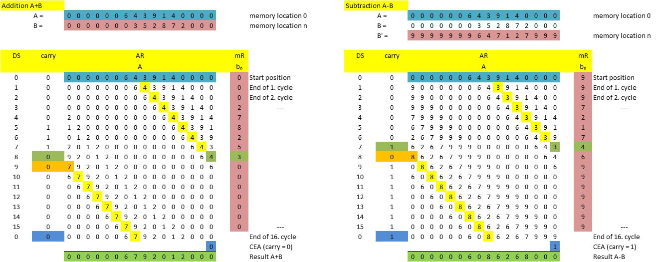
Illustration of the concept of addition (left) in the Mona Lisa computer. The first number A (blue) is loaded into the Arithmetic Register AR, while starting from the Least Significant Bit (LSB) of the second number B (red) the digits are shifted into the mR register. In each of 16 cycles the following steps are made: 1. addition of the three green registers, i.e. the LSB of AR, the current digit in mR and the carry bit of the previous cycle. The result is written into the MSB of the AR AFTER its contents have been shifted one right. If the result of the addition is less than 10 (as in this example, 7) only the AR MSB is written, if the result is larger than 9 the carry bit becomes 1. After the 16th cycle the cycle counter DS becomes 0 again, and a Carry-End-Around is performed (blue). The addition result is now in the AR (green). A subtraction (right) is addition with the 9-complement (B') but otherwise the same 16 cycles. In this example the CEA is 1, leading to the correct result in green. [Philips CAB Mona Lisa Report, via Wolf Schieber]
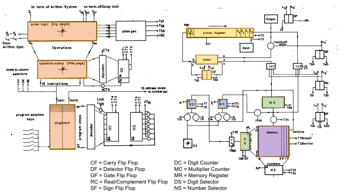
Block diagrams of the main sections of the Mona Lisa. On the left the programming and control part, with the new plug board. Above it the hard wired operation matrix core memory nicknamed "little Jungle". In contrast to the TRANSDECO ring core, in the Mona Lisa this part was implemented solely by circuit blocks. Finally on top the pulse logic ("big jungle") which translated the micro instructions to the 60 different control terminal lines T0-T60. On the right the computer core, with lower right the data memory (purple) and upper left the Arithmetic Register and its shifting loop through the adder (yellow). The two green registers are involved in the addition and subtraction operations, the blue blocks in multiplication and division.
|
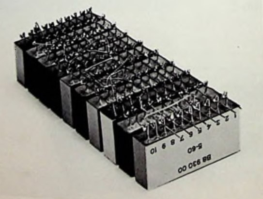
As said, the Mona Lisa was, apart from an improved version of the TRANSDECO, especially a demonstrator for the application of circuit blocks in digital machines. Twelve different circuit blocks were used, nine of the types that had been released by ICOMA, and three preliminary versions still carrying the 2P coding. And finally the CAB had developed three modules by itself, that were not taken over by ICOMA yet, and without guaranteed performance specs. They were simply functional in the demonstrator. In total 680 100kHz Series 1 Circuit Blocks were used in the Mona Lisa, all mounted on standard sized PCB boards. Because the Circuit Blocks were thicker and at least for the simpler functions did not have a smaller footprint than a discrete components solution, the total size of the Mona Lisa increased compared to the TRANSDECO and hence a fourth row of cards had to be added.
The team executing the Mona Lisa was still the same: Scholten architecture and project management, Schieber electronic design, Tierates evaluation, Barel PCB board design. More people from the CAB department gave support. The Mona Lisa demonstrator was finished by 1960. 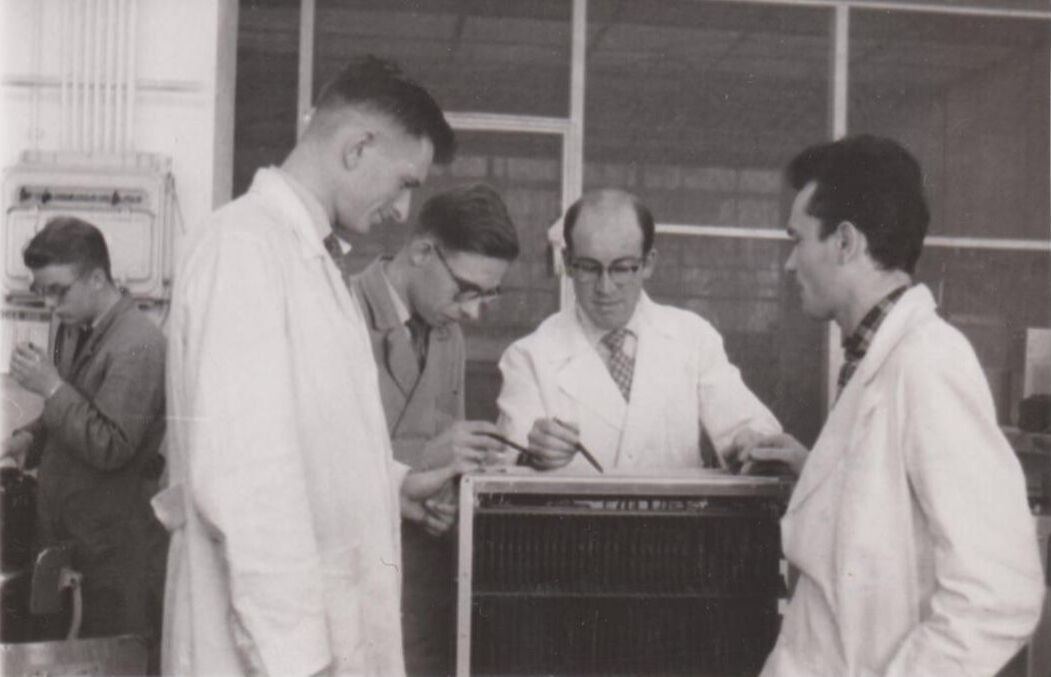
The technical team of the TRANSDECO and Mona Lisa, from left van Silfhout, Tierates, van Kempen, Schieber. [Wolf Schieber]
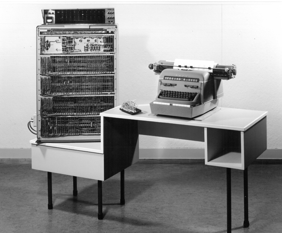
The official publicity picture of the Mona Lisa, here seen from the wiring back side. On the right the Remington electric type writer. [Wolf Schieber]
When the project was completed the principal engineer Wolf Schieber compiled a detailed CAB report on the project, issued July 1st, 1960, and entitled "Digital Computer Mona Lisa". Apart from the complete description of the machine, its circuitry, and micro programming, it also shows examples of realistic business machine applications: invoicing, calculations in British Pounds, but also a complex mathematical computation. The machine had clearly become mature!
|
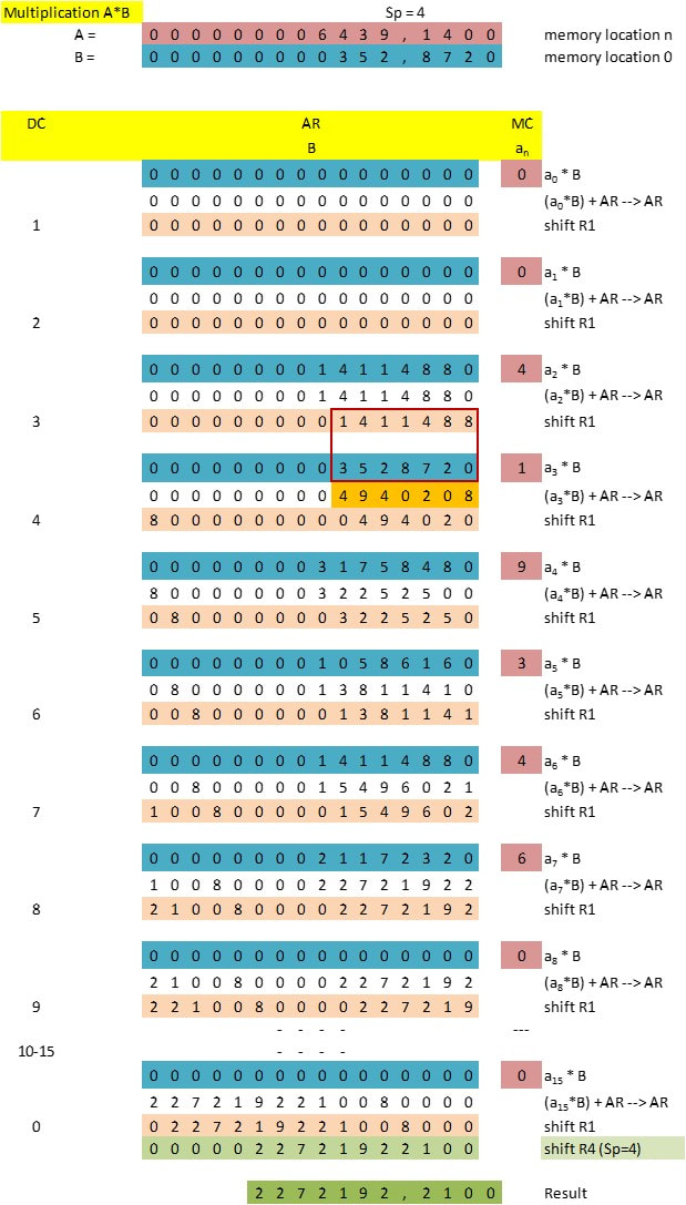
The CAB Mona Lisa report now also contains a full description of the multiplication operation, which is based on repeated sub-multiplications and shifts of the AR. The first step of every cycle, the multiplication of number B times the content of register MC, is performed through repeated summation baaed on the counter MC. It is followed by one addition (the two numbers in the red outlined box, resulting in the orange result) and a cyclic shift. Note that the Carry bit is not used.
An early colour picture of the Mona Lisa, this time from the front side, showing the many differently coloured Circuit Blocks on the PCBs. [Wolf Schieber]
|
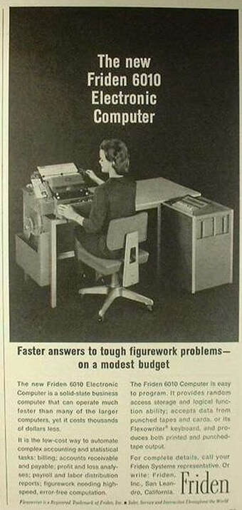
The Friden 6010 office computer, 1963
Although the formal agreement between Philips and IBM started to crumble - IBM began making its own key components, at the expense of suppliers like Philips - the company still did not engage in any serious computer design and manufacturing, and the Mona Lisa project also had no internal use. As a demonstrator of Circuit Blocks it had obviously played its role, though. It was therefore a surprise to all involved when around 1960/61 Philips was approached by the company Friden with the question whether they could take over the Mona Lisa concept and take it into production.
|
Friden was an American company, founded by the Swedish inventor Friden who had developed an innovative electro-mechanical calculating machine. With American venture capital he was able to build a factory in San Leandro, California, while the company in 1957 took over the license of a former IBM/Remington electronic type writer in Rochester, New York. This Flexowriter, which was (still) a large electromechanical tape-writer that could translate typed text into punched cards and punched tape. It was a big business success. In the meantime the company decided to open a second production site in Europe, which became Wageningen in the central Netherlands, using a former cigar factory. Operations started end 0f 1956. The story goes that the CAB also had a Flexowriter for typing punched tape, and that a Friden engineer on his yearly service visit was shown the Mona Lisa, which he reported to his management. That approached the Philips management and the CAB, and in the end a knowledge transfer and support agreement was made, the details of which I don't know. But given the lack of internal interest, I expect that Friden received the design for a reasonable price, but without much guarantee for re-design support. It probably also included the Friden commitment to continue the use of the new Circuit Blocks.
|
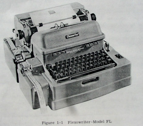
The Friden Flexowriter. On the left the tape puncher is visible.
|
An early prototype of the Friden 6010 being readied for demonstration at the 1961 Hannover Messe. [Flickr]
|
Turning the Mona Lisa into a real product was a far from obvious job. Not only it was the entry of Friden Holland into electronic solutions, but it was - for the time - a revolutionary new design: a small business computer entirely based on transistors, using the new digital technologies. It also required a new mechanical design for use in offices, as well as quality guarantees and all production support. Not surprisingly it therefore took some time to release the new computer, which was called the Friden 6010. In 1961 it was shown and announced on e.g. the Hannover Messe in Germany, but it was not until 1963 that production started. Although throughout these two years Philips CAB probably has given some consultancy (ir Jan Scholten, the Mona Lisa architect occasionally went to Wageningen), but the principal designer Wolf Schieber had left Philips for a new challenge in the US, while Hans Tierates was occupied with the follow-up project of the Mona Lisa, called FIMA (FInancial Machine for Accounting). However, end 1962 Hans Tierates was offered a job at Friden, becoming responsible for production testing. According to Tierates the 6010 was, apart from the outside, electrically 95% identical to the Mona Lisa!
|
|
The 6010 essentially was the combination of a Flexowriter as input/output device, and the Mona Lisa in a new cabinet. It is likely some interface electronics was added to the Flexowriter, while possibly some circuits were re-designed for improved robustness. (In the CAB report Wolf Schieber confirmed that some circuits were just functional without any robustness guarantee, as opposed to the formally released ICOMA Circuit Blocks). From pictures it seems that the three racks of standard sized PCBs were copied one-to-one, with the other support functions relocated to other positions.
As said, the Friden 6010 was launched in 1963, for a retail price of GBP7.850, DM82.250 or roughly HFL90.000. The 6010 was again a business success, being one of the first real compact digital business computers on the market. 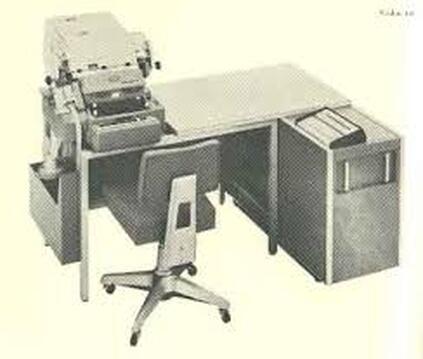
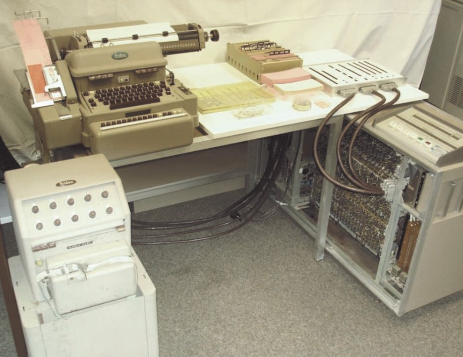
The Friden 6010, with the computer cabinet on the right, the programming interface on top. On the desk left the Flexowriter with the tape and card puncher attached.
|
Advertisement for the Friden 6010.
|
In 2019 the Hamburg Computer Museum obtained a complete Friden 6010 system, shown here. It included the Flexowriter, the computer lower right with a monitoring device connected to it on the desk, and lower left a stand-alone tape puncher. A punch card is shown inserted into the Flexowriter puncher.
|
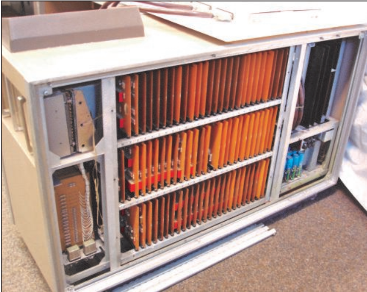
The opened cabinet of the Friden 6010, clearly exposing the three rows of Circuit Block-equipped PCB cards directly copied from the Mona Lisa.
|
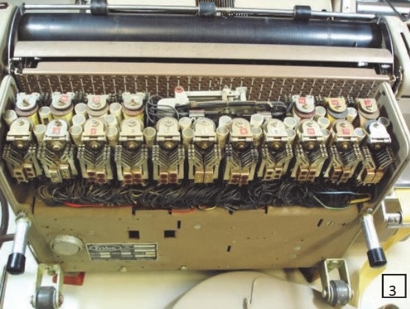
Back-bottom side of the opened Flexowriter, exposing the relays for the puncher.
|
Front-top view of the opened Flexowriter. At the red arrow the card punching needles. [All 4 pictures from "Friden 6010 electronic computer system von 1963" by Prof. Dr. Horst Oberquelle, Hamburg Computer Museum]
|
Both the Flexowriter and the 6010 were a business success, and in 1965 the Wageningen factory was exchanged for an entirely new factory with development lab in Nijmegen, immediately next to the Philips Nijmegen transistor factory where many of the OC transistors were produced. Production steadily grew till almost 1300 people were employed by Friden Holland. In the meantime the company was taken over by the Singer company, famous for its sewing machines, that wanted to diversify into office equipment. Developments at Singer/Friden continued both in California and Nijmegen, with an increasing range of office and shop calculating machines. The 6010 was succeeded by the 6018 around 1965, introducing a large magnetic disk memory, but - at least from the pictures - otherwise unchanged. Around 1968 the 6010 was finally replaced by the 5005/5010 series, which used the first TTL digital ICs and could thus be made more compact. Also the Flexowriter was replaced by a more compact electronic type writer. But all in all the Mona Lisa concept and its Circuit Blocks had been used for a full decade in a highly innovative and successful business machine! However, in some way Friden has missed the major innovation linked to the semiconductor introduction, and in 1972 Friden Holland was closed. The company made a new start as Tealtronic, but also this enterprise did not survive for long.
The Friden 6018, with the new magnetic drum memory attached on the right, but otherwise still identical to the 6010. [Old calculator museum]
|
The large Friden Holland factory and office building along the Sint Teunismolenweg in Nijmegen. [Noviomagus.nl]
|
The Mullard NORBIT family, 1960
By the end of the 1950s Philips was rapidly expanding in many technology domains, and it is therefore not entirely a surprise that a development very similar to the Circuit Blocks of ICOMA/CAB took place in another corner of the company; Mullard in the UK. Here a conceptually similar product family was developed, albeit with slightly different characteristics. It was called NORBIT in the Mullard branding, and promoted in parallel to the Series1 products that were called Combi Elements (most probably only in the UK, on the continent they were marketed as Circuit Blocks). The main differences of the NORBIT vs. Series1 family were:
|
|
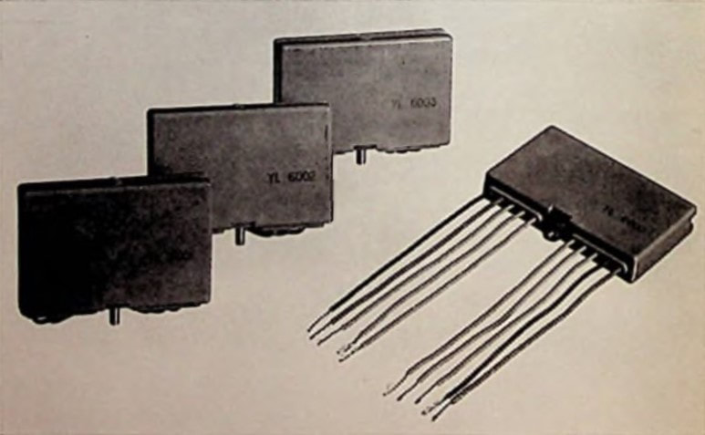
The YL6000-series NORBIT modules. The different pinning and central mounting screw are clearly visible. [Koroncai]
|
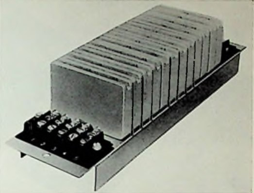
Twelve NORBIT units mounted on a frame. The top side slot gave access to the test points. [Koroncai]
|
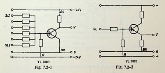
In contrast to the Series1 Circuit Blocks, the NORBITs used active logic circuits, as shown here for the YL6000 and YL6001. The common emitter transistor buffers provided for a signal inversion, and the logic functions thus became NOR, instead of OR. [Koroncai, De transistor als schakelaar]
|
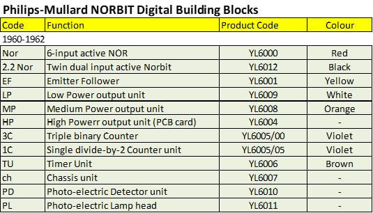
Overview of the Philips NORBIT family of circuit modules.
|
So, although the NORBIT family did contain - and received its name - from the logic functions, its application domain drifted more to hybrid analogue-digital control systems than the pure digital computer domain where the Series1 100kHz Circuit Blocks focussed. This was only due to the 100x lower switching speed, that made it fundamentally unfit for computer applications.
Use of the ZEBRA at the PTT DNL, 1958-1966
Before closing this story it is interesting to have a quick loop at the Dutch PTT Dr Neher Laboratorium and its very successful ZEBRA computer design. As told, in 1959 the first STANTEC ZEBRA was installed at the DNL in Leidschendam, in the group of its inventor Willem van der Poel. In the meantime some organizational changes had been implemented. While van Duuren was still the head of the DNL, some department head changes took place around 1958. dr. ir. Oberman, the head of the Schakeltechnisch Leboratorium (Switching Laboratory) left the PTT to become full time professor at the Technische Hogeschool (Technical university) in Delft. (He still was when I started my study electronics there in 1977, although retiring quickly thereafter). And in 1956 Leen Kosten left the DNL to become full time professor in the mathematics department of the same THD. His role as head of the Mathematische Afdeling (Mathematics department) was taken over by van der Poel. By this time my father, Piet Hooijmans, who had been working in the Radio Laboratorium of jhr van der Wijck, had finished the completion of the experimental 3cm (9GHz) radio transmission system, and decided to switch job by moving to the Mathematische Afdeling of van der Poel.
|
Already with the ZEBRA it had been obvious that the PTT could not justify the cost and effort for internal computer development, having to grant that to STC/STANTEC. Although it created a lot of positive publicity for the DNL, even the development of a ZEBRA successor was beyond the scope of the laboratory. The Mathematische Afdeling of van der Poel therefore focussed on two domains:
|
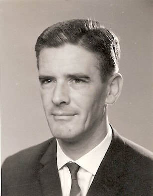
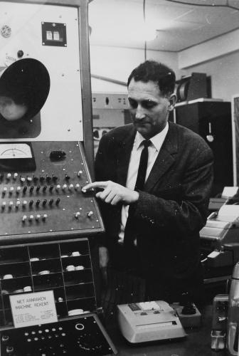
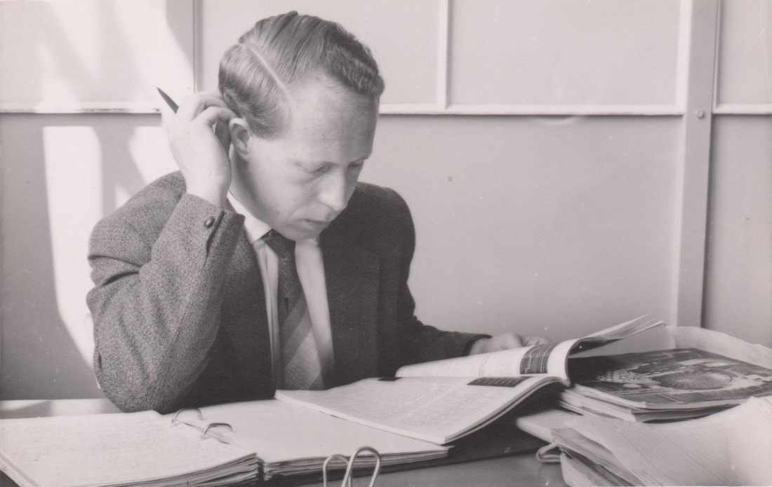
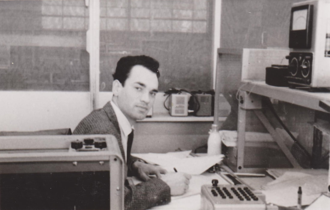
Piet Hooijmans in 1963, when working in the Mathematische Afdeling of the PTT-DNL in Leidschendam.
|
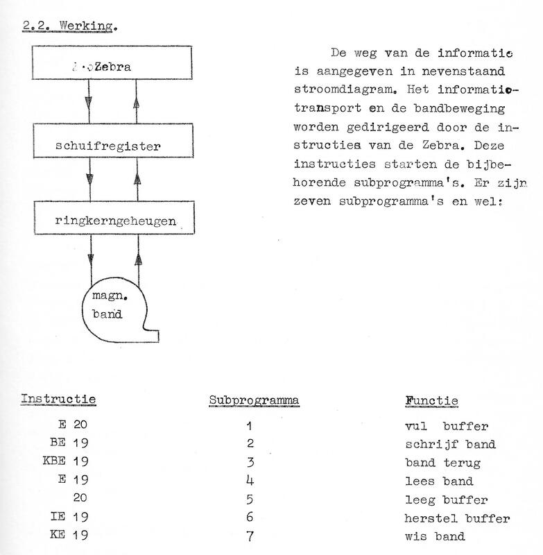
Overview of the ZEBRA tape recorder program memory interface and the new instruction set for for the ZEBRA. [PTT-DNL Beschrijving nr. 68 MA, De koppeling van een magnetische bandrecorder aan de ZEBRA, Piet Hooijmans, februari 1964]
|
Around 1962 two units came available within the MA: a Telemeter 1092-BQ-8A 8kbit ring core memory (for 1092 8-bit words) and an Ampex FR200A magnetic tape recorder. It was decided they would be used to make the tape recorder a program library, with the core memory acting as a buffer between the ZEBRA and the Ampex recorder. However, a double buffer structure was needed (see the block diagram left) because the ZEBRA 128kHz clock rate was too high for the maximum 100kHz of the Telemeter memory. So first a serial ZEBRA 33-bit word was written into a shift register, and then in 8-bit words loaded into the ring core memory. When the ring core memory was filled with 160 words, these were written onto the tape as one block. Because the tape recorder had seven tracks of which one was used for synchronization clock signals, six data tracks were used. In the core memory therefore only six of the eight ring core mats were used, one per track. For storing one 33-bit ZEBRA word therefore six 6-bit core memory words were used, and the 1092 byte memory could contain 182 words. Reading the core memory was destructive and erased the data, but this was restored by re-writing them. The tape capacity was 5000 blocks and thus 800.000 words, a 100-fold capacity extension of the 8192-word ZEBRA drum memory.
For driving the buffer and tape recorder the ZEBRA instruction set was extended with 7 new instructions, two for filling or reading the buffer, the other five for controlling the tape recorder. |
The entire apparatus was designed by Piet Hooijmans using the then usual approach, of standard-sized PCBs with discrete components. So not using the Philips Circuit Blocks, these were either unknown or considered too expensive. However, the functions were roughly identical: flip flops, combining (OR) stages, pulse amplifiers. Transistors used were Philips ASY27 and OC76, the RCA 2N586 plus a few Intermetal OC470, one of the first silicon junction NPN transistors.
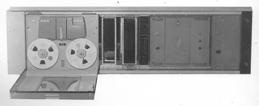
Front view (left) and opened bottom view (right) of the ZEBRA-Ampex tape recorder peripheral. Two drawers with PCB cards were accessible from the front, three others folded out at the back side as shown. [PTT-DNL 68 MA]
|
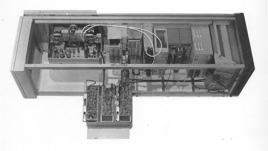
|
|
In parallel to this ZEBRA interface Piet Hooijmans was increasingly involved in the design of digital machines for reading machine writing, one of the main research topics at the DNL. However, these no longer used the ZEBRA but were stand-alone digital machines. Van der Poel became an international celebrity in the computer domain. In 1962 he was appointed part-time professor in computer technology at the University Delft, leaving the PTT to become a full-time professor there in 1967. In 1971 he became member of the Dutch Academie van Wetenschappen (Academy of Sciences). But in 1963, when Piet celebrated his 25 year jubilee at the PTT, he was still his boss and would be so for the next 3 years. By then (1966/67) Piet moved to the DNL Switching Laboratory, van der Poel moved to the TU Delft, and the ZEBRA was replaced, after 9 years of service, by the Electrologica X8. A good moment to end the PTT part of this story. So, after Dammers (star designer at Philips and head of the CAB), and van Duuren (inventor of the Telex-over-Radio), van der Poel was the third high-profile boss and colleague of my father, and the reason he features in this history.
|
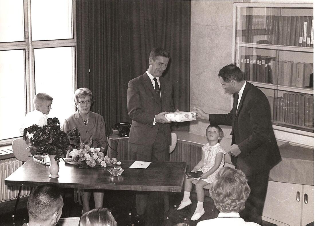
September 20, 1963. Piet Hooijmans, at his 25-year jubilee with the PTT, receives the official present from his boss Willem van der Poel. My little sister Geertje, and my mother Josephine Hooijmans-Tromp look on, while I myself had more attention for the cars on the parking lot.
|
Next Generations Digital Circuit Blocks, 1965-1970
It seems that the Circuit Blocks were a successful product range in the professional applications like business computers (Friden), traffic control systems, and possibly digital telephone exchanges. As a consequence new generations were developed, the first being Series 10, which was released in 1965. Its main innovation was the addition of a second row of pins, bringing the total to 19. This in turn allowed more complex functions or multiple (quadruple) functions to be integrated into a standard-size module. Internally it continued the circuit concepts of Series 1, albeit with a reduction of the supply voltages from +/-24 to +/-12V, and using the more advanced ASY29 germanium NPN transistors. In the Data Book the series is introduced as follows: "The 10-series presents a range of circuit blocks, developed to meet the requirements of the industry for machine-control, process control, data handling, measuring- and signalling systems. With this 10-series systems are designed and built quickly, economically and with the utmost reliability."
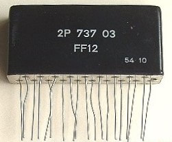
The exterior look of the new Series 10 circuit blocks, with the second row of additional pins. The 2P 737 code again suggest a prototype/pre-series sample.
|
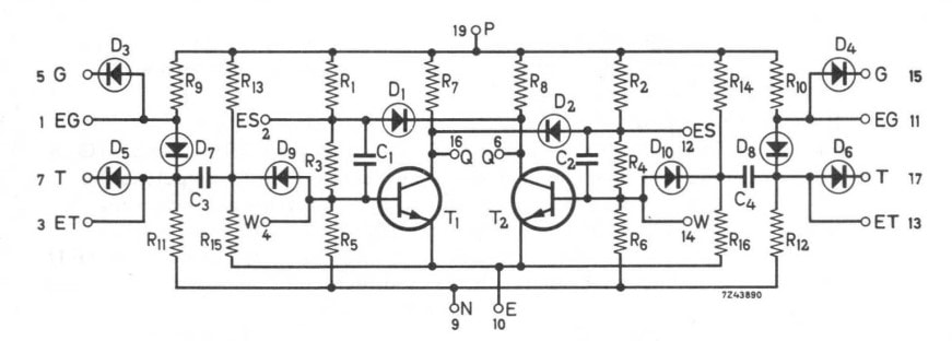
Circuit diagram of the FF11 Flip Flop. The availability of more pins allowed the integration of gate circuitry. [Philips Data Book Components and Materials, Circuit Blocks, 1970]
|
Around 1967 the Series 20 appeared, which was essentially a performance upgrade of Series 1 and 10. In the data book it states these modules are targeted "on the industry for data logging and processing, medium and high speed computers" plus the segments already covered under Series 10. Clock speed had substantially increased to more than 5MHz, almost certainly based on the use of much faster silicon planar NPN transistors, still in TO92 housing.
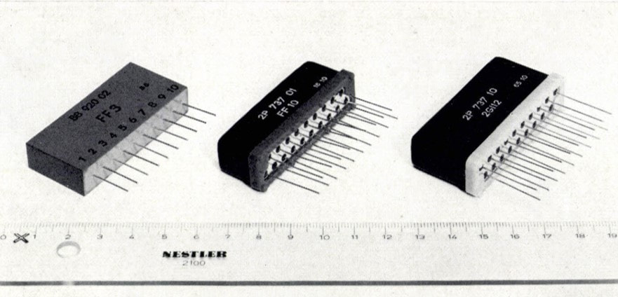
The mechanical and outline evolution of the three successive generations (from the left) Series 1, Series 10 and Series 20. [Philips Technical Review 28, pp.44-56, 1967]
|
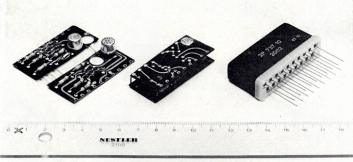
The interior construction of the Series 20 modules: dual PCBs with discrete components and in this case two TO92-housed transistors. Note the two holes in the PCBs for compact folding. [Philips Technical Review 28]
|
|
By this time Philips started a remarkable series of publications related to Circuit Blocks. It started, interestingly, with a publication in the Philips Technical Review (PTR) in 1965 of the Zentrallaboratorium (Central Laboratory) in Hamburg. The exact organisational position of this lab is not 100% clear, but most likely it was the German equivalent of the Eindhoven Central Application Laboratory Building blocks (CAB, the Dammers-lab). In other words, a HIG Electron Valves application lab focussing on Hamburg-produced components. This was a general story about the use of NPN transistors (as opposed to PNP transistors as used so far). A footnote said that a next article would appear from ICOMA on the Series 10 Circuit Blocks. In the meantime, however, in 1965, the HIGs Electron Valves and Industrial Components and Materials (ICOMA) merged into the HIG Electronic Components and Materials (ELCOMA).
This next story, by Mr van Barneveld of what become ELCOMA, in Philips Technical Review 28 in 1967, described both the Series 10 and recently released Series 20 families, highlighting the increased speed of the latter due to the planar silicon transistors. He also states that of the 100KHz/Series 1 to date "a few million have been sold". The next year PTR 29 contained an even longer article by Mr Slofstra of ELCOMA Eindhoven, describing again the Series 10 and 20 as well a number of applications in the industrial machine control. Finally, in these years two books were issued as part of the Philips Technical Library. In 1966 Koroncai and Alving published "De transistor als elektronische schakelaar" (The transistor as electronic switch), which contained both detailed descriptions of the Circuit Blocks, as well as pictures of the Mona Lisa. This series of books and articles highlighting the benefits of Circuit Blocks were undoubtedly driven by the need to defend its position against the rapidly upcoming competing technology: standard logic integrated circuits, both TTL and ECL. Exactly around this time, the second half of the 1960s, these technologies were becoming mature and rapidly started to replace discrete solutions. And Circuit Blocks. |
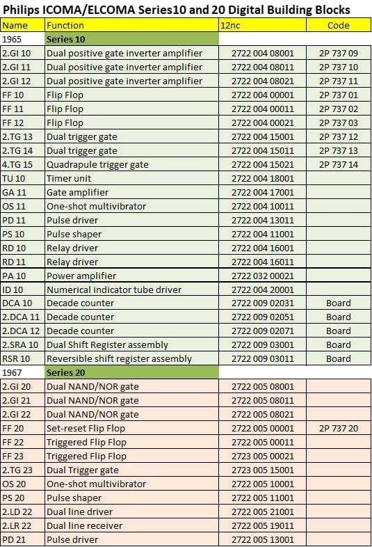
Overview of the Philips Series 10 and 20 Circuit Blocks. [Elcoma Data Book 1969]
|
|
The Circuit Block publications in PTR in 1967 and 68 can thus be considered as the last effort to extend the life of this technology. And indeed, after the 1967 Series 20 no more successor generations would be introduced. This was true for the purely digital high-speed blocks of Series 1-10-20. For more analogue and high power applications, the Series 40 and 50 were developed, focussing on operational amplifier modules and control interfacing, respectively. In the UK Mullard released Series 60 and 61 as successors of the NORBIT, which were also called NORBIT2. Still multi-coloured modules, but their size already indicates they were intended for higher voltage, higher power, industrial control applications. Not for digital computers.
So, although these components could still be ordered for a while, and production continued for another one or two years, it is fair to assume that after 1970 the use of Series 1-10-20 Circuit Blocks rapidly declines, modules being replaced by the emerging integrated circuits. |
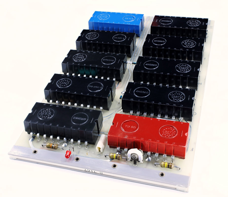
NORBIT2 circuit blocks. [Wikipedia]
|
The Philips Raad van Bestuur early 1968 during a visit to the Volt factory in Tilburg. On the front row from left Casimir (Research), Ooiman (RGT, Domestic Appliances), de Jonge (CFO), Tromp (Vice President), Frits Philips (President and Social Affairs), Hartong (non-Professional Equipment), and furtherst to the right Hazeu (ELCOMA and Lighting). The four men standing are for administration, legal, and commercial affairs. [Regional Archive Tilburg]
|
A symbolical end to the Circuit Blocks era can be seen in the publication of the book "50 jaar elektronische bouwelementen (50 years of electronic building blocks) by ir. Henk Hazeu. In the previous chapters on TV, valves, transistor, and building block developments, as well as innovative centres like the Centraal Applicatielab (CAB), Hazeu has continuously been one of the driving forces. Hazeu was the right hand of Theo Tromp, who preceeded him into the Philips Raad van Bestuur (RvB, Board of Management) responsible for the HIG Electron Tubes. In the early 1950s Hazeu was the Technical Director in the then standard 2-men HIG leadership (one commercial man, one technical man, at that time never a woman). In that role he was the boss of Bert Dammers and his CAB, and the two worked extremely close together. The story goes that Dammers walked into Hazeu's office every Saturday morning (which was still a half working day until around 1962) and then spent hours with him discussing every conceivable technical development. The only drawback seems to have been unhappy mrs Hazeu and Dammers, who were left with the dinner.
|
Around 1957 also Hazeu entered the RvB, taking over the ownership of the HIGs Electron Valves and Lighting. Tromp became the Vice President of the company under president Frits Philips. Also in his new role in the RvB Hazeu continued to drive the components business. In 1968 Hazeu retired from the RvB and did a remarkable thing: he wrote the book mentioned above on 50 years of electronic components. It is a thick book, trying to cover all component, building block, module and system developments that Philips had been involved in for the last 50 years. The same year that Hazeu retired Bert Dammers passed away, after having been ill for some time. Hazeu was really shocked by this loss, because the book is dedicated to his friend Bert Dammers. He wrote:
I really feel the need to dedicate this book to my friend and co-worker BERT DAMMERS, who unfortunately passed away too early. He was an electronic engineer through and through, with a remarkable insight into the possibilities of electronics. In his role, since 1945, as leader of the radio valve application development, later as head of the application laboratories for building elements of the NV Philips Gloeilampenfabrieken, he has contributed substantially to the development of electronic switching technologies. He always strived for simple and practical solutions, that could promote the acceptance of new equipment. His sparkling intelligence and charming personality allowed him to easily win supporters for his proposals.
I retain very good memories of the many discussions where he updated me on the latest developments in switching electronics. The development of new components had to be adapted to support these trends. With gratitude I want to reamrk that these discussions have been a major contribution to the realization of this book.
I retain very good memories of the many discussions where he updated me on the latest developments in switching electronics. The development of new components had to be adapted to support these trends. With gratitude I want to reamrk that these discussions have been a major contribution to the realization of this book.
|
Another interesting detail is that Hazeu mentions three experts that had been the editorial reviewers of his book: Jager, Neeteson, and Uitjens, probably all members of the RBL/CAB/Dammers-lab, of which we have seen mulitple books and articles throughout my stories. Hazeu's book appeared in 1971. After detailed descriptions of valves in all their varieties, transistors, passive and electromechanical elements, a last sub-section in the long chapter Components treats complex/assembled modules: TV tuners, motor control, circuit blocks and ring core memories. The Circuit Blocks in this section receive no less than 7 pages, compared to the average two for other components. Apparently they still had a lot of management attention within ELCOMA! Nevertheless, this can be seen as the last reference to the high speed digital Circuit Blocks, that would from here on rapidly disappear from the scene, replaced by ICs. Nevertheless, it is remarkable that members in the board of a multi-billion company like Philps had such deep technical insight (this is valid for Casimir, Tromp and Hazeu), and after their retirement were willing and able to write a state-of-the-art book about it. The fact that their successors did not have a similar technical drive is undoubtedly one of the reasons for the downfall of the once great company Philips. Also Wim Hazeu, like his friend Bert Dammers, did not get the chance to enjoy his retirement, because he passed away too young, in 1973.
|
|
Summary and conclusions
When I was approached by Wolf Schieber, after he had read the story on the first Philips televisions, with the story that he had worked in the Dammers CAB on the first transistor computer I was totally surprised. since I had never heard of any such activity. The same was true for the Circuit Blocks, which I had never seen. But based on the full documentation, his detailed stories, and nice pictures of both the products and the people, it was too nice a story not to pursue. Also because, as I quickly found out, there were many parallels with the ZEBRA of Willem van der Poel at the PTT-DNL, where my father Piet Hooijmans had also worked on digital machines. The result of all this is the above story, which gives a nice insight into the parallel developments in the domain of computers during the 1950s in the Netherlands.
The conclusion is that this was a very interesting time, with some nice results (the ZEBRA, the TRANSDECO and Mona Lisa, the emergence of Circuit Blocks and their use in the Friden computer). At the same time all these developments were relatively modest, while computer development was a global thing and went very fast. In the end these activities are only a footnote in the overall story on early computer developments, but a nice footnote due to it being intervowen with Philips-CAB activities that were so important in the earlier described TV and tuner development, and work at the PTT-DNL of amongst others my father. And in the process I have been able to dig up some nice technology history facts and pictures.
The conclusion is that this was a very interesting time, with some nice results (the ZEBRA, the TRANSDECO and Mona Lisa, the emergence of Circuit Blocks and their use in the Friden computer). At the same time all these developments were relatively modest, while computer development was a global thing and went very fast. In the end these activities are only a footnote in the overall story on early computer developments, but a nice footnote due to it being intervowen with Philips-CAB activities that were so important in the earlier described TV and tuner development, and work at the PTT-DNL of amongst others my father. And in the process I have been able to dig up some nice technology history facts and pictures.
References
|
As mentioned, this whole story started with the substantial information provided by Wolf Schieber, which included:
|
Wolf Schieber (right) and the author Pieter Hooijmans meeting for the first time during a drink at Valkenswaard, June 2022.
|
Finding details on early computers is not difficult, there are many sites, so I'm not going to mention them all. A simple Google search suffices. On more specific internal topics some very useful sources were:
- The web site Heer De Beer, with good stories on early computer developments in the Netherlands.
- DBNL.org with a similar story
- The master thesis De ontwikkeling van de transistor bij Philips, G.P.J. Verbong, Masters Thesis 307320, TU Eindhoven, 1981.
- Radiomuseum.org remains very useful for component data.
- Philips Transistoren, publicity leaflet on the OC70 and OC71 and their applications, Wiener Radiowerke, Austria, 1956 (?) through Wolf Schieber.
- On Willem van der Poel, the PTERA and ZEBRA there are many stories that are easy to find. But some worth highlighting are
- a personal story with memories at the retirement of his former boss prof Leen Kosten: Delft Progress Report, Papers presented to the symposium Traffic and Control decicated to the scientific work of prof.dr.ir. L. Kosten, ISSN 03404-985x, Delft University Press, 1980.
- a personal story by van der Pole with memories on the evolution of the ZEBRA
- Less is More in the fifties, encounters between logical minimalism and computer design, during the 1950s, Mol, Buyllinck, Daylight, IEEE Annals of the history of computing, 2018.
- STANTEC ZEBRA - digital electronic computer, Information Processing Division, Standard Telephoen and Cables Inc, 1961
- 50 jaar studieverzameling, EWI, TU Delft, 2019, with pictures of the ZEBRA in their museum
- a personal story with memories at the retirement of his former boss prof Leen Kosten: Delft Progress Report, Papers presented to the symposium Traffic and Control decicated to the scientific work of prof.dr.ir. L. Kosten, ISSN 03404-985x, Delft University Press, 1980.
- On the PTT Dr Neher Laboratorium organisation and activities
- D. van de Nieuwe Giessen, Onderzoek en ontwikkeling bij KPN - Een geschiedenis van de eerste honderd jaar, KPN Research, 1966
- Honderd jaar telefoon -De geschiedenis van de openbare telefonie in Nederland 1881-1981, Chapter 7 Onderzoek by P.J. Hooijmans, PTT, Hoofddirectie Telecommunicatie, 1981
- P.J. Hooijmans, De koppeling van een magnetische bandrecorder aan de Zebra, Beschrijving nr. MA 68, Dr Neher Laboratorium, PTT, februari 1964. Plus second book with same reference containing all technical drawings.
- D. van de Nieuwe Giessen, Onderzoek en ontwikkeling bij KPN - Een geschiedenis van de eerste honderd jaar, KPN Research, 1966
- Philips has published quite some books on digital circuitry and design, they can all be found on the internet:
- P.A. Neeteson, Vacuum valves in pulse technique, Book IX, Philips Technical Library, 1955, 2nd enlarged edition 1959
- P.A. Neeteson, Junction transistors in pulse circuits, Book IXa, Philips Technical Library, 1955
- P.A. Neeteson, Analysis of bistable multivibrator operation, Book X, Philips Technical Library, 1956
- A.H. Bruinsma, Multivibrator schakelingen - inleiding in de robottechniek, Philips Technical Library, 1958
- D.J.W. Sjobbema, Schakelen met transistors, Philips Technical Library, 1960
- A. Koroncai, R. Alving, De transistor als elektronische schakelaar, Philips Technical Library, 1966
- For the Circuit Blocks more information is available
- The Wikipedia page on combi elements and NORBITS, contains some useful links to early data sheets:
- Guide to circuit blocks (Combi elements) and their use in digital systems and equipment, Mullard Sub-Assemblies Bulletin, No.9, November 1962.
- NORBIT sub-assemblies YL.6000 series, February 1962
- Mullard Combi Elements data sheets, 1963
- Developments in the field of electronic computers, W. Nijenhuis and H. van de Weg, Philips Technical Review, Vol.26, No.3, pp67-81, 1965
- A new system of digital building blocks, for industrial measuring and control systems, D. Gossel, G. Kaps, W. Schott, Philips Technical Review, Vol. 26, No.4/5/6, pp.164-170, 1965.
- Digital circuit blocks, E.J. van Barneveld, Philips Technical Review, Vol.28, No.2, pp.44-56, 1967.
- The use of digital circuit blocks in industrial equipment, C. Slofstra, Philips Technical Review, Vol.29, No.1, pp.19-33, 1968.
- Philips ELCOMA Data Book Components and Materials, Part 1, Circuit Blocks and Input/Output Devices, September 1970. Contains full data sheets of all Circuit Block series from 10 to 61.
- ir H.A.G. Hazeu, 50 jaar elektronische bouwelementen 1921-1971, Philips ELCOMA, 1971.
- The Wikipedia page on combi elements and NORBITS, contains some useful links to early data sheets:
- The main Friden stories can be found on the Noviomagus site here and here
- The old calculator web museum contains many descriptions of old business computers and calculators.