Introduction
|
Part.1 of this history so far covered the joint efforts by Philips Research, the Apparaten Lab and the Radiobuizen Lab to develop competitive television receivers. This was a bit of an uphill battle, since television transmission only took place in the UK and on an experimental basis in France, both with by then already outdated standards of 405 and 441-lines, respectively. Philips promoted its own 567-line standard, fairly close to the US NTSC one, but support for this outside the Netherlands and Denmark was minimal. Nevertheless Philips had invested in a full experimental television system, with a studio, a transmitter and a few hundred experimental TV sets distributed in Eindhoven. Transmissions Philips Experimental Television (PET) started in 1948. At the Radiobuizen Lab some 35 engineers, including my father Piet Hooijmans, were allowed to build their own television set with materials supplied by Philips and based on the latest RBL reference designs. In the meantime the HIG Apparaten launched its first generations of TV sets into the British and French markets, the TX380 platform in 1938 and the next year the TX390. They sold in moderate numbers but were an important part of the learning curve. In the US, in contrast, the effort to launch the Protelgram rear projection TV module as developed in Research, became a costly failure and production had to be stopped abruptly in 1949. Radio valve development, however, went very well, with first the compact Rimlock and then the cheaper Noval family being launched in 1949, including increasing numbers of valves dedicated for television. So by the end of the decade the company was ready for the next step, expectations were high, but what it desperately needed now was a European television market!
|
Chapter navigation
|
New 625-line television standardization
|
All first generation Philips television sets based on the TX380 and TX390 platforms were made for the British 405-line and French 441-line standards, plus a pre-series TX594U on the Philips 567-line standard. But not everything was quiet on the standardisation front. In July 1948, at the CCIR meeting in Stockholm, Russia proposed a 625-line standard! The exact origins are not entirely clear, but the most plausible story is that immediately after the war, in the Russian-occupied zone, captured German engineers were forced to re-design NTSC sets received from the Americans under the Lend-Lease war program into a 50Hz-compatible system. That resulted in a 625-line/50Hz architecture with a line frequency of 15.625Hz, which is indeed very close to the 15.750Hz of the 525-line/60Hz NTSC system. One can say this is the same exercise Philips did with its 567-line standard, although with fewer compromises.
|
Definition of line numbers
There is a logic in the definition of the number of lines. To start it must be odd, given the interlacing principle of the TV standards. Next, because all TV receivers are using the 50 or 60Hz line rate for harmonic locking the vertical and horizontal time base oscillators, it is desirable to have integer multiples between these rates and half the 50/60Hz. For the then existing standards these ratios were as follows: 405 = 3 x 3 x 3 x 3 x 5 441 = 3 x 3 x 7 x 7 525 = 3 x 5 x 5 x 7 So the closest odd number to 15.750 (525 x 30 of the NTSC system) for a 50Hz system would be 627 (since 627 x 25=15.675), or 629 (15.725), but both don't have favourable factors: 627 = 3 x 11 x 19 629 = 17 x 37 Therefore 625 was chosen, with the almost ideal factors: 625 = 5 x 5 x 5 x 5 The Philips standard was an interesting variance of the 405-line standard: 567 = 3 x 3 x 3 x 3 x 7 The only real oddity in this system is the new 819-line standard, where the factor 13 is exceptionally high: 819 = 3 x 3 x 7 x 13 |
This 625-line proposal generated quite a shock and received immediately considerable support from technical experts, not from the political side. This was namely yet another standard next to the 405, 567 and 819-line proposals. And there was one more complication: the Russian standard positioned itself roughly halfway the Philips 567-line standard, which was at the time the highest resolution (quasi)-operational standard, and the French 819-line high-definition proposal, still a few years out from operational use. It proposed an 8MHz channel bandwidth with 6MHz video and 6,5MHz sound carrier distance. Many countries (i.e. the national telecom organisations like the Dutch PTT) and set makers considered this 8MHz channel bandwidth at the time as overly ambitious and uneconomical. It would allow fewer channels in VHF and make receivers expensive. And then there was of course the starting Cold War, so adopting a Russian standard was not a politically correct thing to do.
Like in all democratic standardization committees the solution to opposing and conflicting proposals is a working group, which was formed to tour the countries and laboratories that proposed a standard. France played the power card, and on November 20, 1948 François Mitterand, the later president but then Secretary of State for Information, issued a decree that France had officially chosen for the 819-line standard. France also put heavy pressure on its French-speaking neighbours Belgium and Luxembourg. Efforts of the Dutch government to align with Belgium on a single standard thus didn't lead to anything, since the Belgian government wanted to keep all options open. Throughout 1949 the CCIR committee must have visited all players including Philips, which gave demo's of its 567-line system and the PET transmissions. Target was the next meeting May 1950 in London. In this context it is interesting to note that since 1949, after his retirement from Philips at the age of 60, Balthasar van der Pol had become the chairman of the CCIR. By this time a competing/alternative 625-line system was proposed, mainly by engineers of Telefunken of which at least Walter Bruch was a former Russian prisoner who worked on the Russian 625-line standard. This system copied the 625-line/50Hz basics of the original Russian standard, but at reduced channel bandwidth (7MHz instead of 8), video bandwidth (5MHz vs. 6MHz) and sound carrier (5.5 vs. 6.5MHz). Interestingly the new Bundesrepublik Deutschland, founded May 1949, was a strong supporter of the 625-line standard with the main argument that they wanted no two different standards in the two German zones. However, the BRD was not yet a member of the CCIR! At the May meeting in London there was still no agreement, if only for the reason that Britain could not let a meeting in London agree on anything else than a British standard. However, support for the ageing 405-line standard was minimal outside the UK, while the French 819-line high-definition standard was seen as too far-fetched. That the pressure to come to a single standard and a compromise with the French was high is illustrated by the fact that end of 1949 even a 729-line standard was proposed [from De geschiedenis van Koninklijke Philips Electronics NV by J. Blanken, pt V, p37]. Although details are scarce, this seems to have been a Belgian initiative to a compromise with the French. But these had issued their state decree and didn't want to accept a compromise. The battle was in fact between the two versions of the 625-line standard.
Like in all democratic standardization committees the solution to opposing and conflicting proposals is a working group, which was formed to tour the countries and laboratories that proposed a standard. France played the power card, and on November 20, 1948 François Mitterand, the later president but then Secretary of State for Information, issued a decree that France had officially chosen for the 819-line standard. France also put heavy pressure on its French-speaking neighbours Belgium and Luxembourg. Efforts of the Dutch government to align with Belgium on a single standard thus didn't lead to anything, since the Belgian government wanted to keep all options open. Throughout 1949 the CCIR committee must have visited all players including Philips, which gave demo's of its 567-line system and the PET transmissions. Target was the next meeting May 1950 in London. In this context it is interesting to note that since 1949, after his retirement from Philips at the age of 60, Balthasar van der Pol had become the chairman of the CCIR. By this time a competing/alternative 625-line system was proposed, mainly by engineers of Telefunken of which at least Walter Bruch was a former Russian prisoner who worked on the Russian 625-line standard. This system copied the 625-line/50Hz basics of the original Russian standard, but at reduced channel bandwidth (7MHz instead of 8), video bandwidth (5MHz vs. 6MHz) and sound carrier (5.5 vs. 6.5MHz). Interestingly the new Bundesrepublik Deutschland, founded May 1949, was a strong supporter of the 625-line standard with the main argument that they wanted no two different standards in the two German zones. However, the BRD was not yet a member of the CCIR! At the May meeting in London there was still no agreement, if only for the reason that Britain could not let a meeting in London agree on anything else than a British standard. However, support for the ageing 405-line standard was minimal outside the UK, while the French 819-line high-definition standard was seen as too far-fetched. That the pressure to come to a single standard and a compromise with the French was high is illustrated by the fact that end of 1949 even a 729-line standard was proposed [from De geschiedenis van Koninklijke Philips Electronics NV by J. Blanken, pt V, p37]. Although details are scarce, this seems to have been a Belgian initiative to a compromise with the French. But these had issued their state decree and didn't want to accept a compromise. The battle was in fact between the two versions of the 625-line standard.

The timing format of a Gerber-norm (CCIR B) TV signal. The line duration is 64us (equivalent to 15.625kHz) of which 12us is used for blanking during the horizontal fly-back. Modulation is negative, with 100% modulation equivalent to white and 30% equivalent to black.
|
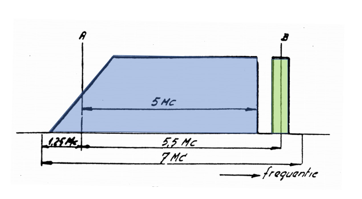
The equivalent spectrum of a Gerber-norm (CCIR-B) TV signal. Blue is the video spectrum, with its vestigial sideband around the picture carrier. Green is the FM sound carrier at 5,5MHz distance. Total channel bandwidth is 7MHz.
|
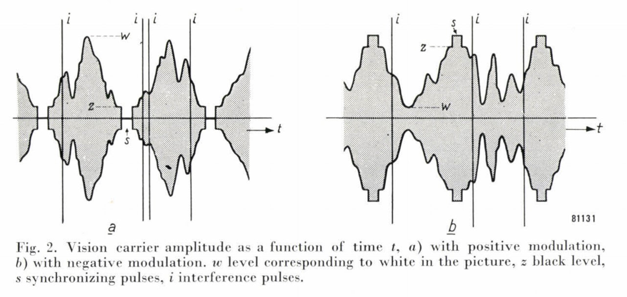
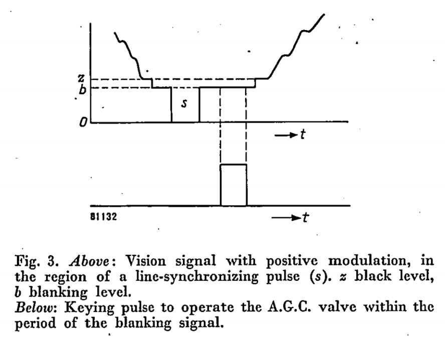
Useful comparison of video signals with positive modulation (left) and negative modulation (right). On the right a picture from the same article showing the timing of the AGC keying pulse. [Philips Technical Review Vol.16 1954 p.195]
|
|
As a next step yet another sub-committee was created, led by what was considered to be the neutral chairman Dr. Walter Gerber, an engineer of the Swiss telecom organization. During a meeting in Geneva Switzerland in July 1950, the countries Sweden, Denmark, Italy, the Netherlands and (Flemish) Belgium agreed on the modified 625-line standard, which was consequently for a long time known as the "Gerber-norm". Of course Germany supported the proposal in the background. But in the next formal CCIR meeting May 1951 in Geneva still no agreement could be reached on a single European standard, and from that moment onwards four different standards were to exist in parallel. To complicate matters further Vlaanderen (Flanders, the Dutch-speaking part of Belgium) defined their 625-line system as a compromise with the French 819-line standard, so AM sound and positive modulation, whereas Wallonie, the French-speaking part of Belgium as well as Luxembourg, opted for the 819-line system but squeezed into the 7MHz channel. It goes without saying that Russia stuck to its original 8MHz 625-line standard, the UK to its 405 lines and France continued its path towards 819 lines. As a typical result their were consequently six different television standards in Europe!
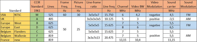
Overview of the six different TV standards that would be used in the 1950's in Europe. The letters identifying the standards (here A-F and M) as we know them today were not defined until a 1961 CCIR meeting, but are added here for easier referencing.
Philips switch-over from 567 to 625 lines, 1949
It is now more or less clear how Philips dealt with the new emerging 625-line standard. In the beginning there must have been some frustration, because the company was in the end pushing its own 567-line standard, which was at least technically up to then the best compromise between the high definition French ambitions and the low end 405-line UK proposal. However, the company must have seen that support for their proposal was at least lukewarm, with Denmark the only country effectively supporting it. [Denmark started experimental transmissions of 567-line TV on May 1, 1949]. So my guess is that rather quickly after the formal emergency of the 625-line standard in the August 1948 Stockholm meeting of the CCIR at least some people will have started to look into it. Surprisingly in the book on the history of Philips [pt.V, p36] it is claimed that "the development group" - which I suppose must have been the Apparaten Lab - "took the decision for 625 lines already July 8, 1948", which seems quite unrealistic to me.
But fairly quickly, most probably towards the end of 1948, there must have been a turning point in the Philips strategy, because by that time rumours were building up that the PET transmissions were going to be interrupted. And indeed, effectively May 1949 the PET transmissions were stopped, only to be re-started by September 5, 1950. During this period the system was converted from 567 to 625 lines. Almost certainly during the same period the PET transmitter was replaced and upgraded by a more modern version with a 60km range. All officially distributed television sets (whichever number remained of the SX861A and all TX594U's) were recalled and upgraded too.
Some hints at the time line of these changes can be found in the release dates of the TX594U. The first (unknown) circuit diagram release is from 24-7-1948, which suggests the sets according this concept would have been ready second half of 1948, This was probably the original 567-line version. The next release is 17-3-1949, and is probably the original design of the 625-line version of the set starting from the design and valve arrangement of 1948. It is highly probable that this concept did not work, simply because it was not possible to get decent performance with the restrictions of the valve count and architecture as originally chosen. A number of modifications were thus required, mainly the insertion of one UF42 each in the three IF branches, bringing the total valve count to 26, the highest number for any of the early television sets. So the known documentation dated September 12, 1949 of the TX594U thus refers to the MODIFIED and UPGRADED 625-line version of the set, and is NOT the original 567-line design! This both explains the unusually high number of valves, as well as the fact that the few existing sets were used for 625-line reception. Details of the updated TX594U will be discussed in the next section.
Also at the Radiobuizen Lab the switch must have been implemented. Some hint at the mild chaos that must have reigned during early 1949 when the line-rate switch took place can be seen from the fourth circuit diagram I have from the lab, which I will code as RBL4. Based on the original 567-line RBL1 design from August 1948, it saw three updates within one month, all signed off by "vdK" which must have been Ir van der Knaap. They are dated March 3, March 10 and April 1st. This is very exceptional, because Philips didn't like official version updates due to the associated administrative work. But even more remarkable is the architecture. Where the RF, IF and frame line ups are identical to earlier versions, the line output and high voltage sections have been split. Both have been designed with old valves, the EL38 power amplifiers and EA50 instead of the ubiquitous EY51, which is still used in the HV section. An EBC3 acts as HV oscillator and the total HV section makes the impression to be based on an old design. The sudden use of EL38's instead of the Rimlock valves somehow suggests this is a Mullard design, using their pet valve. All in all a strange design given the timing, architecture and its 24 valves, and as far as I can see never taken into production.
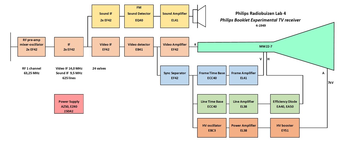
Block diagram of a Radiobuizen Lab reference design from April 1949, almost certainly after re-design from 567 to 625 lines. The separate 8kV high voltage line up is almost certainly to allow flexibility in view of the still ongoing standard definition.
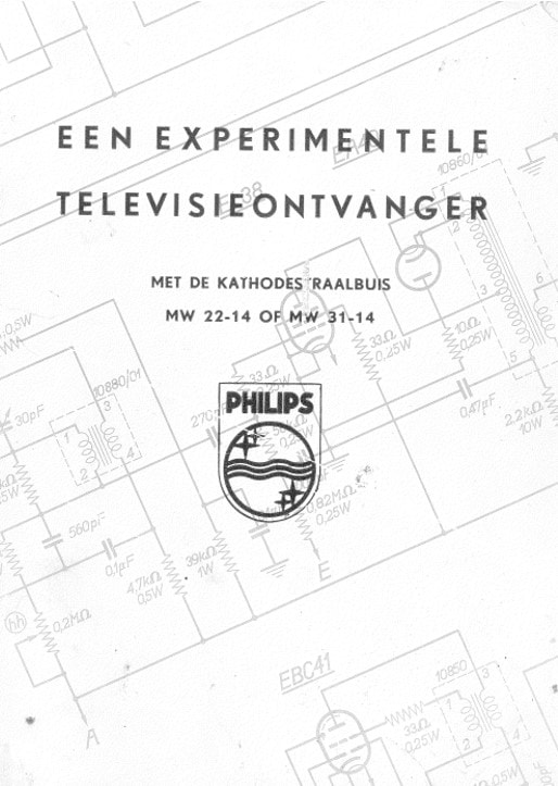
But then I received information that put this RBL4 reference design in a different perspective. In May 1949 Philips issued a 35-page booklet entitled "Een experimentele Televisieontvanger - met de kathodestraalbuis MW22-14 of MW31-14" (An experimental television receiver - with cathode ray tubes MW22-14 or MW31-14) written by J. Jager, one of the Radiobuizen Lab engineers and a regular EAB author. (Later, in 1953 he would also author part 3C of the prestigious Philips Electronic Valves series). It seems that Philips, as a gesture to the many people that had invested in one way or the other in 567-line television, wanted to prepare them for the coming 625-line standard and the required conversion. The booklet contained a complete reference design plus a detailed explanation of its functioning and alignment. And this reference design was exactly identical to the above RBL4 design! And as a bonus it contained a picture of a typical reference design, which turns out to be almost identical to the home-built TV of my father.
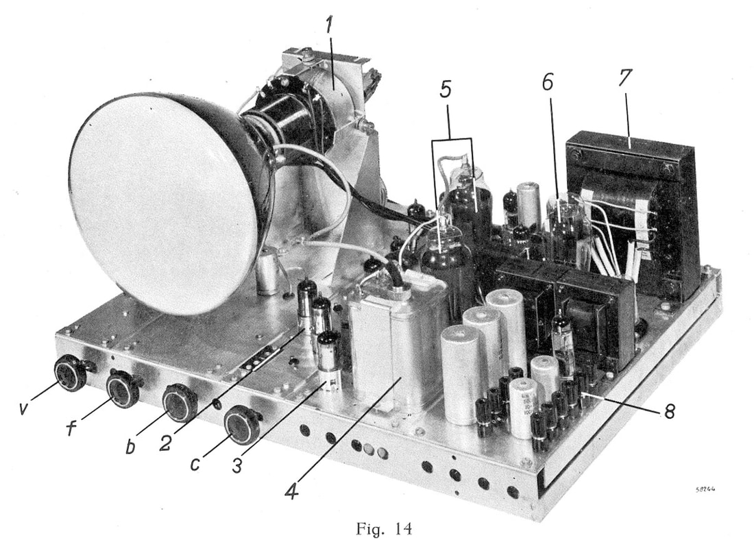
Picture of the experimenal TV receiver from de booklet by Jager. The control knobs: v=volume, f=focus, bbrightness, c=contrast. The numbers: 1. deflection jug, 2. RF mixer EF42, 3. EBC41 in high voltage supply, 4. line output transformer with built-in rectifier, 5. EL38's, 6. AZ50 rectifier, 7. power supply transformer, 8. connectors for power supply measurement, also for modules before final chassis assembly. [Een experimentel televisieontvanger booklet]
|
|
Another indication of the 567-to-625 switch timing is from the EAB articles listed earlier. In the January 1949 issue on the EA40 the references for circuits are still for 405 and 567 lines. However, already in the July 1949 article on Extra High Voltage supplies the only reference made is to 625 lines! So this also puts the timing of the switch-over in the first halve of 1949.
The same must have happened with the home-built sets like the one of my father. Because Piet had been using his home-built set to watch the experimental PET transmission, his set must have been 567 lines and ready before May 1949, which fits with all known dates. (And he had left Philips before the 625-line PET transmissions started, so he can't have watched those). Clearly he and the other do-it-yourself set builders also were allowed to convert their set to the new standard, but I have no traces of the timing nor the circuit diagram used for it. One can thus speculate that the RBL2 schematic is already the one modified for 625 lines. Interestingly the date, 3-3-1949, is from the same week as the first modification of the TX594U, 17-3-1949. Unfortunately there are no indications of frequencies or line rates in the diagram. Another indirect hint at the timing is the memorandum of Alma as shown above, dated 2-3-1949. The Philips decision to switch to 625 lines made all home-built TV's useless overnight, and I can imagine that the about 35 owners of a home-built set all bombarded the key architects with questions how to convert their set to the new standard, thus triggering Alma's measures towards some level of control that I presented earlier.
The same must have happened with the home-built sets like the one of my father. Because Piet had been using his home-built set to watch the experimental PET transmission, his set must have been 567 lines and ready before May 1949, which fits with all known dates. (And he had left Philips before the 625-line PET transmissions started, so he can't have watched those). Clearly he and the other do-it-yourself set builders also were allowed to convert their set to the new standard, but I have no traces of the timing nor the circuit diagram used for it. One can thus speculate that the RBL2 schematic is already the one modified for 625 lines. Interestingly the date, 3-3-1949, is from the same week as the first modification of the TX594U, 17-3-1949. Unfortunately there are no indications of frequencies or line rates in the diagram. Another indirect hint at the timing is the memorandum of Alma as shown above, dated 2-3-1949. The Philips decision to switch to 625 lines made all home-built TV's useless overnight, and I can imagine that the about 35 owners of a home-built set all bombarded the key architects with questions how to convert their set to the new standard, thus triggering Alma's measures towards some level of control that I presented earlier.
|
Together with the 625 lines also higher Intermediate Frequencies (IF) were introduced! All sets so far had used a picture carrier of around 11-14 MHz with the sound 3-4 MHz lower at 8-9 MHz, depending upon the standard of course. The combination of higher bandwidth, experience with the difficulties to get sufficiently steep IF bandpass characteristics at lower IF and probably also the emergence of better valves all pushed the IF roughly a factor two higher. A handwritten note in Piet's file gives the following new frequencies:
|
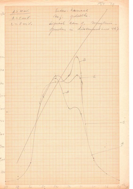
Measurement by Piet Hooijmans dated April 15, 1949 of the video IF pass band characteristics. This both confirms the date of the conversion as well as the shift to a twice higher IF. The horizontal axis runs from 18 to 27MHz.
|
The 625-line update of the TX594U, 1949
After the 150 TX594U sets had been recalled once the 567-line PET transmissions were discontinued, they were converted to the 625-line standard. As explained above, it is very likely this happened in two steps, with a first concept defined by March 1949 and the final (upgraded) one September of the same year. According Jac Janssen the modifications of the set were not fundamental, maintaining the 27,5MHz VIF as used in the 567-line version. That implies that the sound IF had to move 1MHz down from 23 to 22MHz. Another major modification was of course the change from sound AM to FM. I suspect, but am of course not sure, that it was initially tried to achieve the new 625-line operation using the same valve line-up, albeit with widened bandwidth. This probably introduced performance deficiencies due to insufficient gain, requiring (step-wise) three additional UF42 amplifier valves in the three signal chains (RF/IF video+sound, IF/BB video and IF/BB sound). We only know the final outcome dated September 12, 1949, which used a record 26 valves.
|
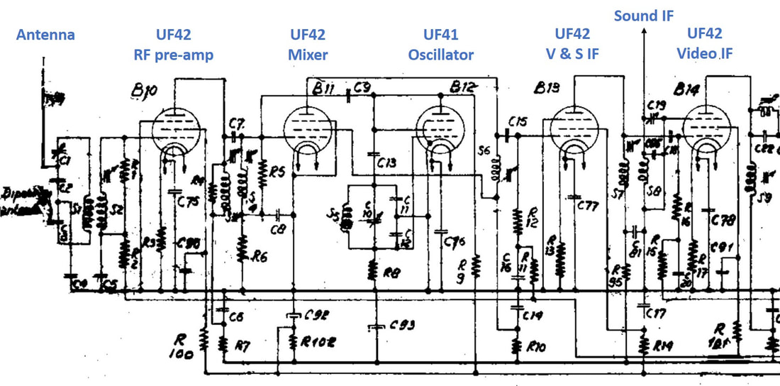
One of the modifications in the 625-line TX594U was a new mixer-oscillator concept. Where the 567-line version had used a single self-oscillating MO valve UF42, the upgraded set used a unique separate RF oscillator valve UF41. This was again probably driven by the need for more gain and/or lower noise, given the wider bandwidth. For the same reason there were three UF42 Video IF amplifiers.
|
The TX594U was the first television set to introduce FM audio detection, using a Foster-Seeley discriminator. Because of the high conversion loss a three-stage IF driver chain was required, using two UF41's (B4-B5) and a UF42 (B6). After FM detection using a dual diode UB41 (B7) the sound baseband signal was fed to the triode amplifier section of B8 (UBC41) before the final power amplifier output valve UL41 (B9). All in all a 6-valve audio chain. Also noteworthy is the fact that the spare diode of the UBC41 (B8) is used as detector in a protection circuit, which would switch of the supply of the picture tube to protect it against burn-in in case of malfunctioning deflection circuits.
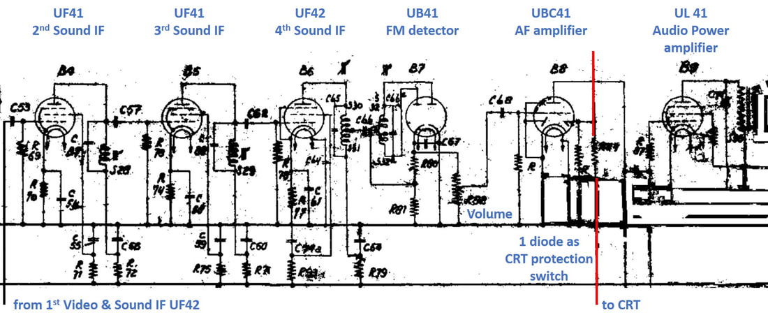
A bad quality copy of the TX594U audio chain circuit diagram, with left the IF input and on the right the output transformer. Note that this TV uses a Foster-Seeley frequency discriminator (B7).
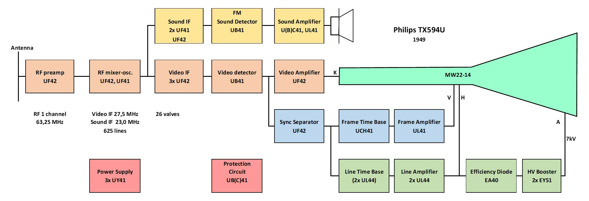
Block diagram of the Philips TX594U after its conversion from567 to 625 lines during the first half of 1949.
Other remarkable, or at least non-standard, features of this set: it used a UF42 instead of the standard UL41 as video output amplifier; there was no UCH42 line time base oscillator valve, it still used the 1948 TF380 design using two parallel UL44 power amplifiers. Finally this set was the first to introduce the newer MW22-14 picture tube; still 22cm/9" but now for 0,3A serial heater supply. With three power rectifiers UY41 the total number of valves came to 26, the highest number for any direct view television set of the first generations, and making it relatively expensive. From that perspective it was fortunate that this was not a really commercial set, in the absence of operational television broadcast in the Netherlands.
New valves: Noval
|
Around 1948 an alternative valve socket type emerged in the US, coded B9A but commercially called Noval. It was based on the same all-glass bases as used in the Philips Rimlock series but had three advantages: it had 9 instead of 8 pins, it was more compact, and used the open space of the deleted 10th pin as a reference, thus no longer requiring the sensitive pimple of the Rimlock base. The advantages of the Noval base were quickly recognized, both for the technical reasons mentioned but also because the Rimlock base essentially was only used in Europe, thus limiting export opportunities to the US. With the Noval base a global market appeared. Philips, being the largest valve supplier in Europe, thus decided to make the switch to Noval, followed by all other European players. During 1949 most Rimlock types were 1-to-1 modified into a Noval type through a modest internal re-arrangement of the pin connections. These valves were coded in the 80-series, maintaining the E, P or U family coding. Examples were the EF42-EF80 and the EQ40-EQ80. In contrast to the Rimlock series, Noval also had a miniature 7-pin version, the B7G socket. This was used for e.g. the EB41-EB91 conversion.
But it were not only straightforward copies of Rimlock valves that were introduced in Noval. The migration to the new socket was also used to introduce new valves directly in this family, skipping a Rimlock version. The best example is the ECL80 triode-pentode, a very versatile valve that undoubtedly emerged from the typical RBL optimization efforts to limit the number of valves. Where in the RBL1, 2 and 4 reference designs there were multiple functions like raster and line time bases that used ECC40's followed by an EL41, with the ECL80 these functions could be reduced to a single valve. Although I can't prove it, I clearly see "the hand of Dammers" in this approach. An intermediate case was the EQ40-EQ80, where the EQ40 had been available as prototype valve for some time but never commercially released. We thus find it in many reference designs of RBL, but the commercial version was only the EQ80 as launched in 1949. From 1950 onwards all new platforms would switch to the Noval family. |
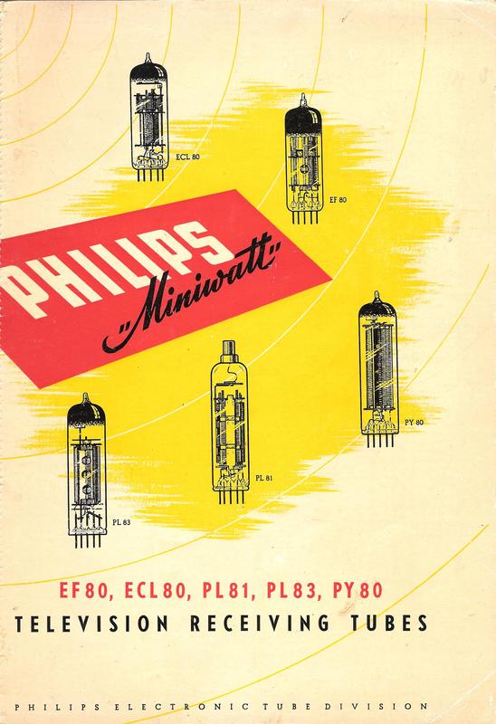
The Philips booklet introducing the new Noval television valves. Date of issue was March 1950.
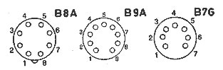
On the left B8A Rimlock socket, centre the B9A Noval and right the B7G miniature 7-pin socket.
|
|
|
|
|
|
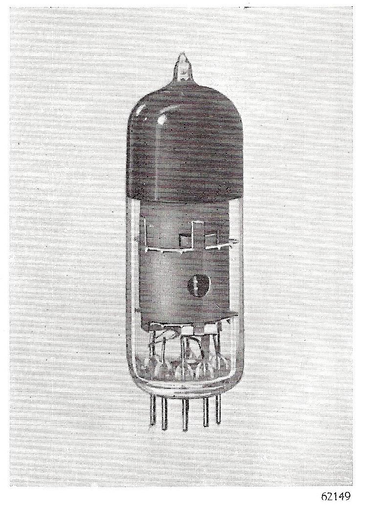
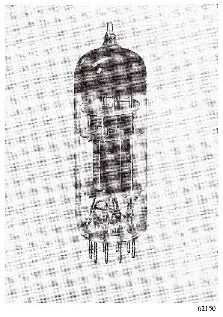
The five television valves introduced in the Noval series by Philips in 1950. From left to right the EF80, ECL80, PL81, PL83 and PY80.
[Philips Miniwatt Television Receiving Tubes, 1950]
[Philips Miniwatt Television Receiving Tubes, 1950]
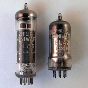
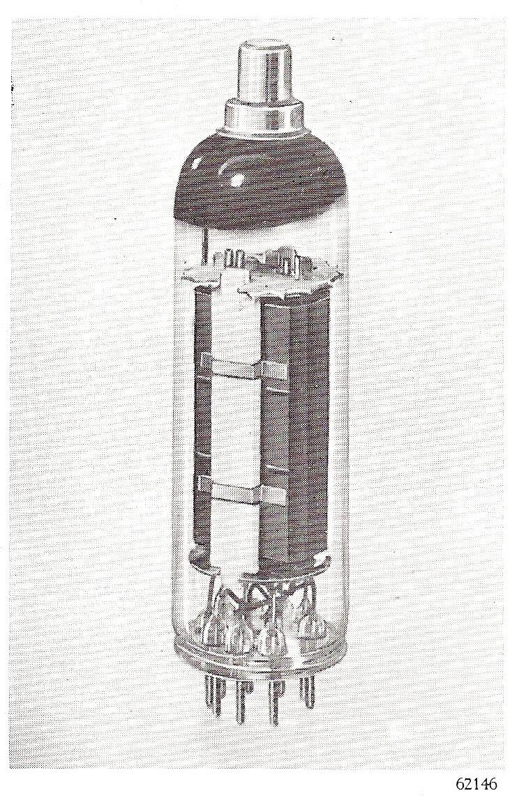
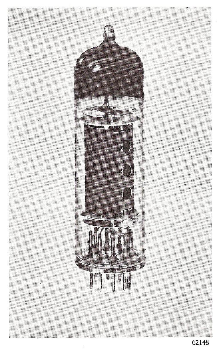
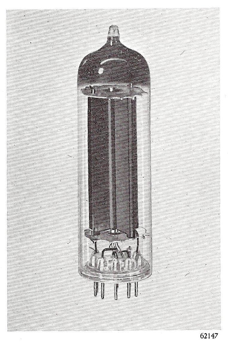
On the left the new Noval EL86, on the right the Rimlock EL42. The more compact base is clearly visible.
|
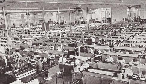
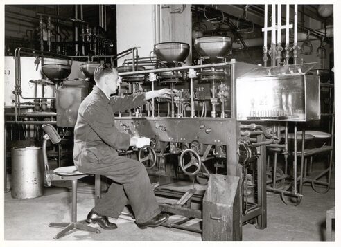
Radio valve manufacturing was a very labour-intensive operation, and soon a second factory was required next to the central one in Eindhoven. Already in 1946 a factory was opened in Sittard (Zuid Limburg), originally in a convent but in 1947 a brand new large facility was opened. On the picture we see hundreds of women assembling radio valves. [EAB]
|
|
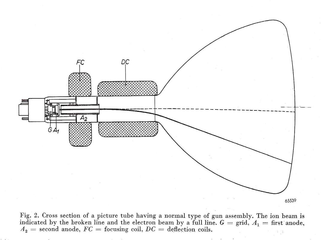
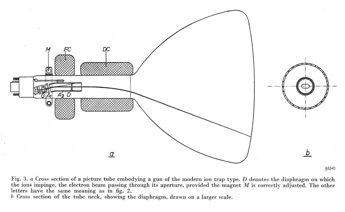
In parallel also the picture tube development didn't stop. Whereas most first generation TV's had used the MW22-7, from 1948 onwards small improvement steps were implemented. The MW22-14 introduced the 0,3A current fed heater (also providing 50% power efficiency), the MW22-17 a new 12-pin socket that would remain standard, the MW22-18 introduced a metal coated tube for better static discharge. But the MWW22-16, introduced second half of 1950, had a real innovation: the ion trap. This solved the problem that the electron gun of the valve not only generated electrons but also some residual ions. Since these are heavier than electrons they don't get deflected by the magnetic coils and consequently hit the screen around the centre, giving over time a dark burn-in spot. Initially some products (MW31-20 to -23) were fitted with thin aluminium strips behind the screen in an effort to catch stray ions, but this was not very effective. The ion trap, in combination with a slanted electron gun, turned out to be the most effective solution to avoid ion burn in, see the pictures. Although the ion trap was still introduced in the 9"/22cm MW22-16, this would be the last 22cm CRT upgrade and from now the 12"/31cm MW31 would be the leading screen size. Mullard did release an even larger 16" circular picture tube, the MW41-1, with a full metal sheet cover across the back of the picture tube. However, this CRT was never adopted by Philips internally and only used sporadically by other British set makers. Instead, the next step would be more rectangular screens.
|
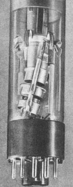
The slanted electron gun in the MW22-16 with ion trap. [EAB]
|
|
|
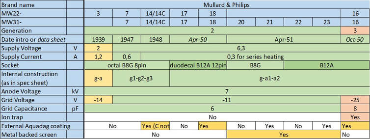
Overview of the different versions of the 2nd and 3rd generations 9" MW22 and 11" MW31 picture tubes between 1947 and 1951, culminating in the MW22-16 and MW31-16 with ion trap.
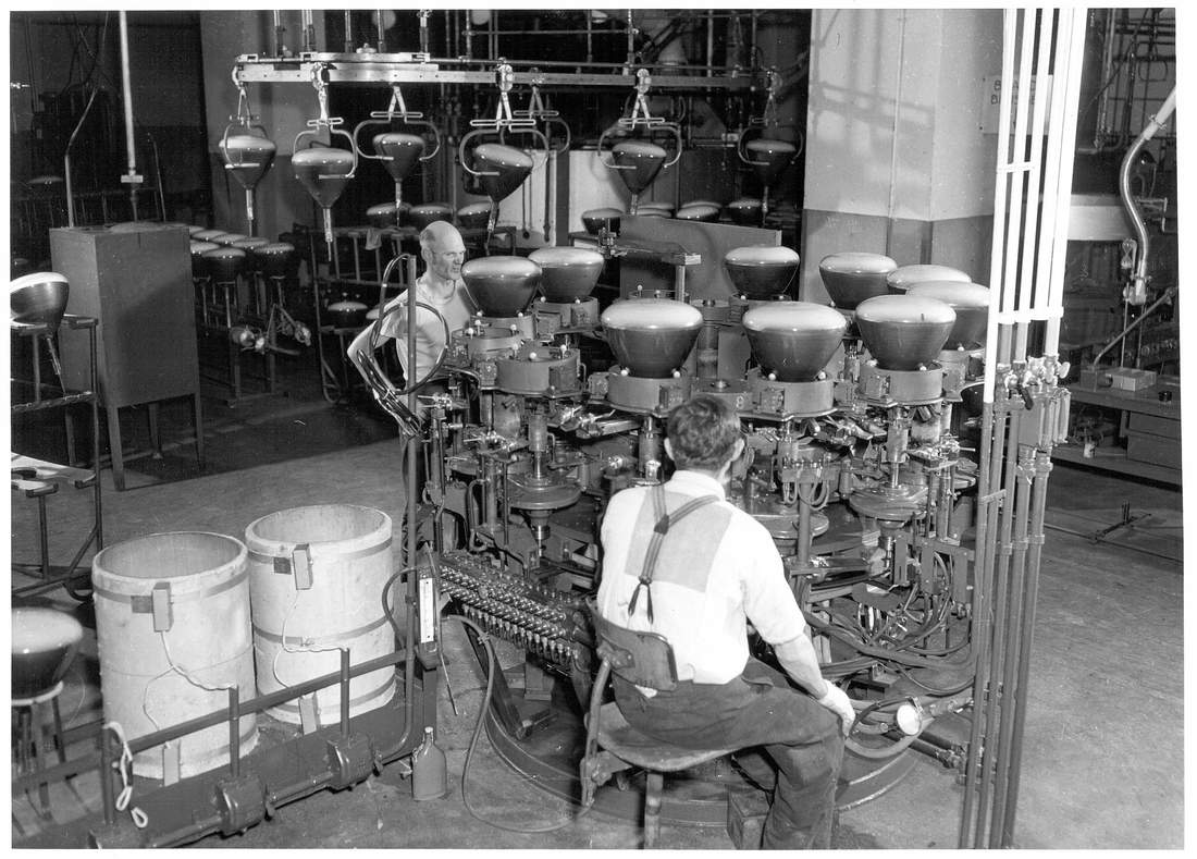
The caption to this picture reads: "The picture shows bulbs for Mullard Television Picture Tubes which have just left the automatic machine which welds neck tube to the bulb at high temperatures. In order to avoid mechanical stress at the point of junction, the bulbs are immediately placed in an annealing furnace where they travel for 2,5 hours along a tunnel , the temperature of which is graduated such that the glass cools very slowly. The bulbs are transported from the joining machine to the furnace along a runway from which is suspended a vacuum chuck. To minimise risk of strains in the glass, the chuck is kept at the same temperature as the bulb." [Mullard Outlook, Vol.1, No.6, Februari 1951, from the Valve Page]
|
"The picture shows part of the process of welding the metal cone to the glass face of a Mullard 16" Television Picture Tube MW41-1. This wide-angle tube presents one solution to the problem of larger pictures without increasing cabinet weight and bulk". This last round TV CRT was never used by Philips, and only in three sets of EKO and Ferguson. Internally Philips would switch to the rectangular mW36 and MW43. [Mulllard Outlook Vol.2, No.6, March 1952 via the Valve Page]
|
The new RBL Noval-based reference design, 1950
|
The booklet "Television receiving tubes" introduced above and published March 1950 first introduced the five new valves that would form the basis of the third generation of Philips televisions. They were:
|
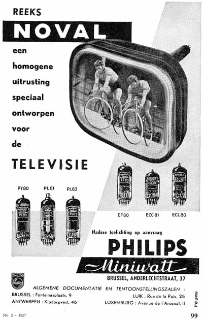
A Belgian Philips advertisement for the new Noval series of valves. Apart from the EQ80 it is exactly the list of valves from the Television Receiving Tubes booklet.
|
The second half of the mentioned booklet contains a detailed reference design of a 625-line television receiver. This is fully in line with the internal Philips policy to switch to this new standard as defined early 1949. However, we should realise that by this time the compromise Gerber-norm (CCIR-B) standard was not yet formalised - that would only happen May 1951 - and interestingly the reference design uses a picture-sound carrier distance of 5,25MHz, where the final standard would be 5,5MHz. Since the booklet is published by the Electron Tube Division the design clearly came from the Radiobuizen Lab, and I will thus code it as RBL5.
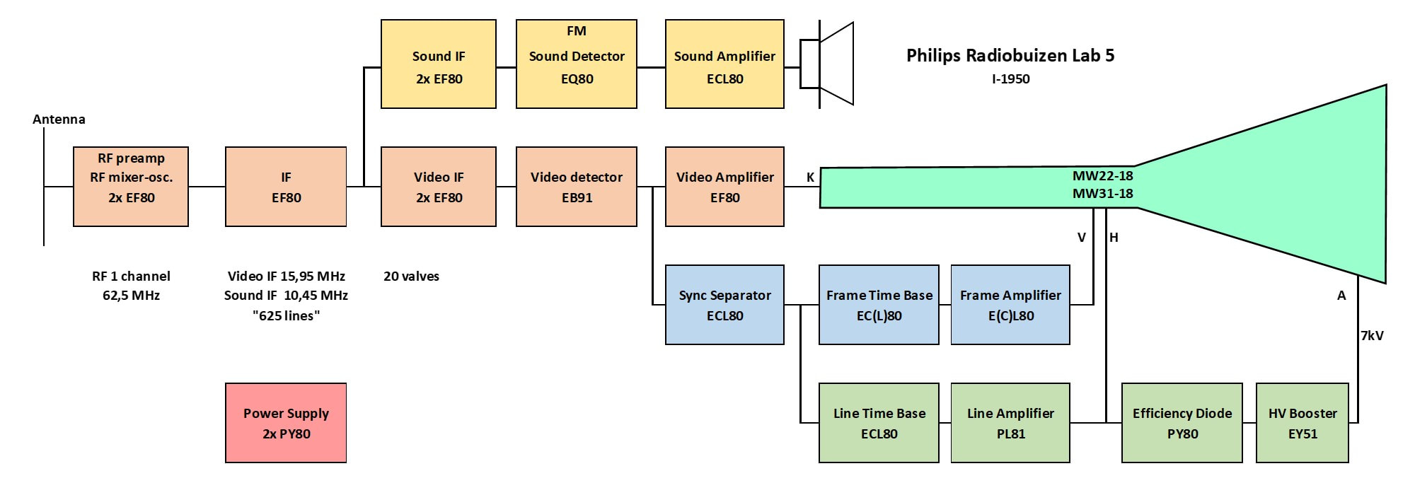
Reference design for a 625-line television reciever as published in the Philips booklet introducing the new Noval television valves. Since at the time (March 1950) the standard was still under discussion the reference design used 5,25 instead of 5,5MHz video-sound carrier distance.
Another interesting characteristic is that the reference design still uses the "old-style" low IF frequencies, 15,95MHz picture carrier and 10,7MHz sound carrier. This is a bit surprising, since we know that the RBL internally switched to twice higher IF's, see my fathers television as well as the - to be discussed - third generation Philips televisions (TX400 and beyond). The most plausible explanation is that Philips wanted to keep the "new" higher performance IF concept confidential, and only published a lower performance reference design. I haven't found a single Philips set that actually used this 15,95/10,7MHz IF. A possible explanation for the choice is that it would allow amateurs to re-use 10,7MHz filters from radio receivers.
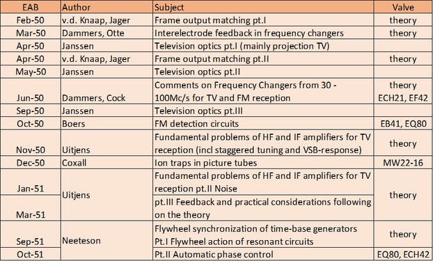
Television related articles in the 1950 and 1951 editions of the Philips Electronic Application Bulletin.
The RBL5 design incorporated the latest insights and developments from the Radiobuizen Lab, a lot of which was published in the Electronic Application Bulletin in 1950, see the table above. Most significant is that, compared to 1948-49, the articles are much more focussing on the theoretical background of circuit performance than on actual valve applications. The only exception is the article by Boers on FM detection, which covers all forms of frequency demodulation including of course the EQ80. The three leading television developers of the RBL each contributed articles: van de Knaap and Jager on frame output matching, Dammers on the RF mixers and Uitjens on IF amplifiers. The latter article especially introduces the Gain-Bandwidth Product concept - still the basis of all broadband amplifier design - as well as Staggered Tuning and the design of Vestigial Side Band (VSB) video amplifiers.
As a next step most of the articles published by the RBL authors in the EAB magazine were the basis of a number of new books in the series of Electronic Valves that was started by Philips in 1940. Between 1950 and 1953 a further eight volumes appeared, most of them covering valves and circuits for television, the remainder covering radio design. All books were translated in English, French and German and were very successful. Even today these books are still sought after and are still considered the reference literature for valve-based television and radio design. At the same time Freek Kerkhof and W. Werner of the Research group Haantjes published their book "Televisie" which was based on internal courses given throughout the company. Also this book became a standard, with three updated and revised editions up to 1969.
As a next step most of the articles published by the RBL authors in the EAB magazine were the basis of a number of new books in the series of Electronic Valves that was started by Philips in 1940. Between 1950 and 1953 a further eight volumes appeared, most of them covering valves and circuits for television, the remainder covering radio design. All books were translated in English, French and German and were very successful. Even today these books are still sought after and are still considered the reference literature for valve-based television and radio design. At the same time Freek Kerkhof and W. Werner of the Research group Haantjes published their book "Televisie" which was based on internal courses given throughout the company. Also this book became a standard, with three updated and revised editions up to 1969.
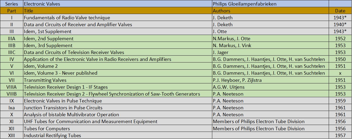
The complete series of books in the Electronic Valves series as published by Philips. The eight volumes in the green rows were all published between 1950 and 1953 by the Radiobuizen Lab group of the Electron Valves HIG. As indicated, the planned volume 3 by Dammers et.al. on receivers seems to have been planned but never actually published. The three first books marked with an asterisk were published at the indicated date in Dutch, whereas the translated volumes had to wait till 1949 after the war. At the end of the decade there was another wave of releases that completed the series to a total of 17 volumes.
|
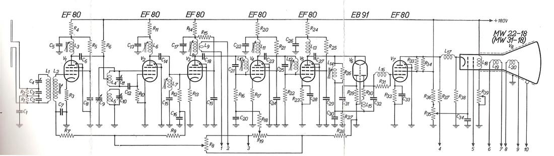
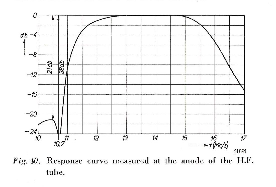
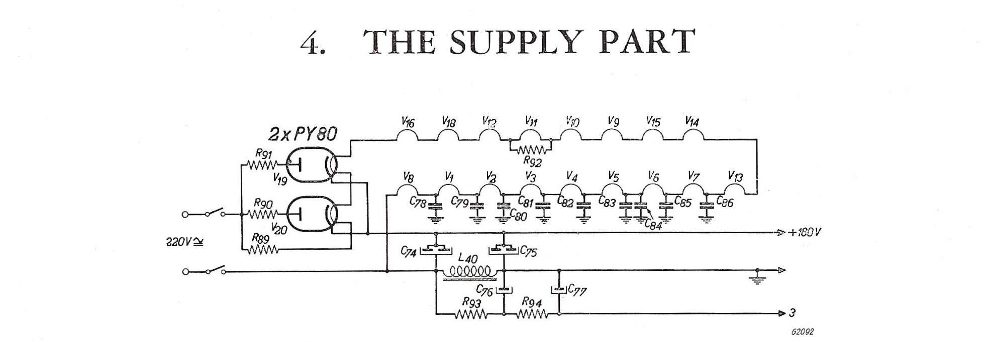
The RF-IF-video chain is based on six EF80's and one EB91. The first EF80 is an RF amplifier (65MHz in the reference design, which is close to the 67,25MHz of the PET transmitter), the second the mixer-oscillator. This is followed by four EF80 IF amplifiers in a "staggered tuning" arrangement as developed by Uitjens, the EAB article of which is announced in the booklet. (It would appear in the October EAB). The four anode loading tuned circuits of the 2nd to 5th EF80 (V2 to V5) are tuned to 11,55MHz, 12,72MHz, 15,60MHz and 14,00MHz, respectively, with varying load resistances. Overall this gives an almost flat video IF pass band characteristic. The VSB characteristic around the picture carrier at 15,95MHz is achieved by the IF roll off starting at 14,7MHz, resulting in exactly the required 3dB damping at the picture carrier.
The first half of the EB91 dual diode acts as the video peak detector, while the second diode provides a level clamping of the black level (here still 25% of peak modulation, in the final standard 30%) such that the black level is independent of contrast control. The design introduces the MW22-18 picture tube, using the external metal coating but not yet the ion trap. |
|
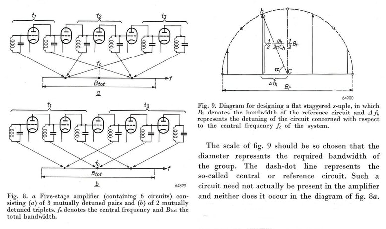
The principle of staggered tuning for achieving high bandwidth flat IF bandpass characteristics. [Philips EAB November 1950]
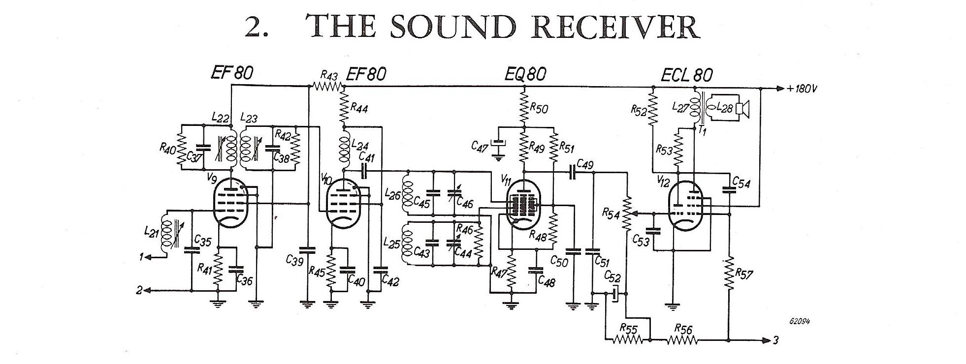
The sound channel basically didn't change from the earlier RBL reference designs, apart from the valve replacements. The two tuned IF stages provide selectivity around the 10,7MHz sound carrier as well as the required 10Vpp input voltage for g3 and g5 of the EQ80 phi-detector. Since the Radiobuizen Lab clearly loved its new ECL80 valve it is used here as a two-stage audio amplifier, replacing the original EL41. As we will see later this concept would not be copied by the Apparaten Lab, which stuck with a single power pentode (PL83) in its new designs.
|
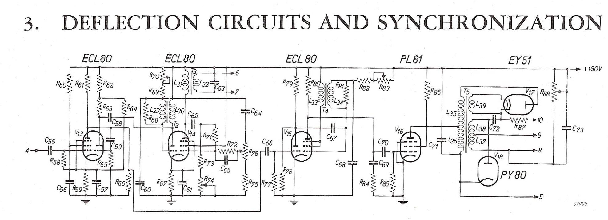
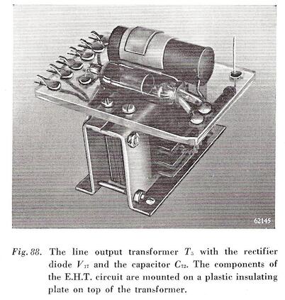
Especially in the synchronization and time base circuits the benefits of the ECL80 come out. Only three of these valves are needed for synchronization separation, frame time base generation and amplification, and line time base generation. They replace the typical four valves used up to then in the TX380 and TX390 platforms, including two expensive ECH's, and this is clearly a cost reduction. The line driver uses the newly introduced PL81, with the PY80 replacing the EA40. The EY51 continued being used as the high voltage rectifier. A picture showed the new line output transformer assembly, with the EY51 and the capacitor C72 mounted and a plastic isolation plate on top of the transformer. The booklet gives two deflection circuits. One conventional at 7,5kV, providing a square image on the centre of the picture tube. Alternatively a so-called "Double-D" concept is presented, where the entire surface of the picture tube is used through the use of higher 9kV voltages.
For completeness the power supply circuit is shown below. |
|
Start of television transmission in the Netherlands, 1951
|
Despite all developments described so far, the formal situation in The Netherlands and most of its neighbours was by the end of the decade still the same: no public television transmissions. Whereas FM radio transmission was seen as a potentially useful addition to the existing AM radio systems, television was often seen as a luxury thing, for which there was hardly a need from the still impoverished population, struggling to rebuild the devastated countries after the war. Especially in The Netherlands the austere cabinet under prime minister Willem Drees thought nothing of television, and didn't want to spend any government money on it. At the same time developments in the US and UK showed that television was probably something that would come anyway, so on October 18, 1948 an inter-departmental television committee to investigate the matter was established by the Dutch government. After two interim reports, on December 12, 1949 the government announced that it would allow the establishment of an experimental television system in The Netherlands for a period of two years. In practice this meant collaboration between Philips (still the biggest supporter) and Nozema, the collaboration between the Dutch PTT (which was targeted to provide the transmitter infrastructure as it already did for radio) and the large public radio broadcast organizations (the Roman Catholic KRO, protestant NCRV and VPRO, socialist VARA and general AVRO). In parallel The Dutch government participated in the CCIR in its effort to come to a single European standard. All this resulted in two more or less parallel tracks: Philips and its friends trying to get a television broadcasting system off the ground, and the government involved in the standardization of what that system would be.
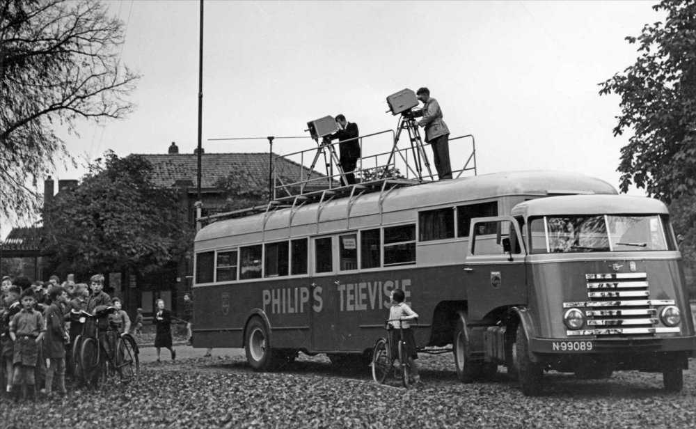
The brand new Philips Television DAF trailer for TV reporting outside the studio during its presentation to the press November 1951. It was handed to the NTS, but showed many technical problems, and repeatedly had to return to Eindhoven for upgrades and repair.
|
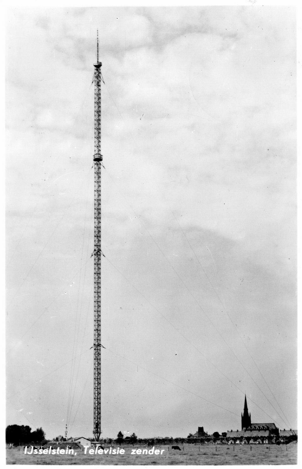
The new transmitter tower for television in IJsselstein called "Zender aan het Paardenveld". [Het Utrechts Archief]
Although Philips was officially still promoting its 567-line standard, we've seen that internally the company had effectively linked its destiny with the new 625-line Gerber-standard. Early 1949 the Radiobuizen Lab was rolling out its reference design update for the 625-line receiver set, while the Apparaten Lab went about converting the TX594U's to the new standard. In parallel another group, probably with support from Rodenhuis' Professional Valves group in the RBL, converted the PET transmitter. By August 1950 the moment had come to re-start the Philips Experimental Transmissions, but now based on 625 lines. On August 11 the following announcement went out, directed to the many television amateurs in the country that had built sets based on the 567-line system.:
|
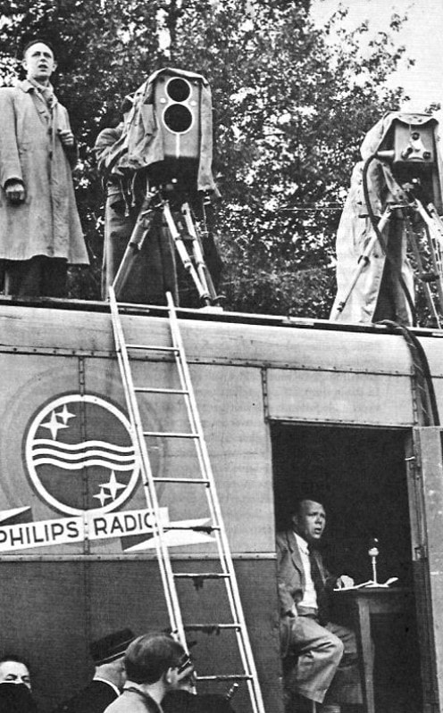
The camera and technical van of Philips during the live PET transmission of the soccer match PSV-FC Eindhoven on Spetember 10, 1950. [Philips Archive]
|
"Television amateurs in Holland will shortly be informed that the experimental transmissions of the Dutch television transmitter will be changing from 567 to 625 lines. Such a change of the number of lines will of course require the modification of the approximately 400 television receivers that are presently in use. This modification to the new number of lines involves no great difficulties and, in Holland, will be carried out by the users of the equipment themselves because it has been established that 90% of all equipment that is presently in use was constructed by amateurs. "
On September 5, 1950, the 625-line PET transmissions started, with already on September 10 a live transmission of the local soccer derby of PSV (the Philips Sport Vereniging) against FC Eindhoven. In this period Philips was also visited by a CCIR delegation, following the July 1950 Geneva meeting, where it was decided that the different standard proposals were to be reviewed in more detail. In a 1962 interview Johan Haantjes, the NatLab group leader, describes this as follows: "For a moment it seemed that [Europe] would align on a single standard of 625 lines. In those days - it was 1950 - the entire CCIR (Comité Consultatif International du Radio, the official standardization body) came to visit the Philips [Research] Laboratory. We were the first to show television pictures with 625 lines. In our studio we had made it possible to also watch images with different line numbers: with one flip of a switch we could compare them. We also gave a demonstration with a wide screen television. Philips made a great impression that we were able to show all this." |
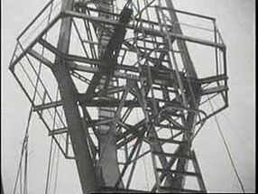
Part of the towers lattice construction. All these pictures are from a 1951 Polygoon cinema news reel at the opening of the transmitter. [Wikipedia]
|
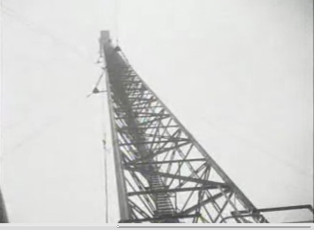
The 223m high antenna mast seen from below. The tower itself was 200m with an additional 23m antenna on top.
|
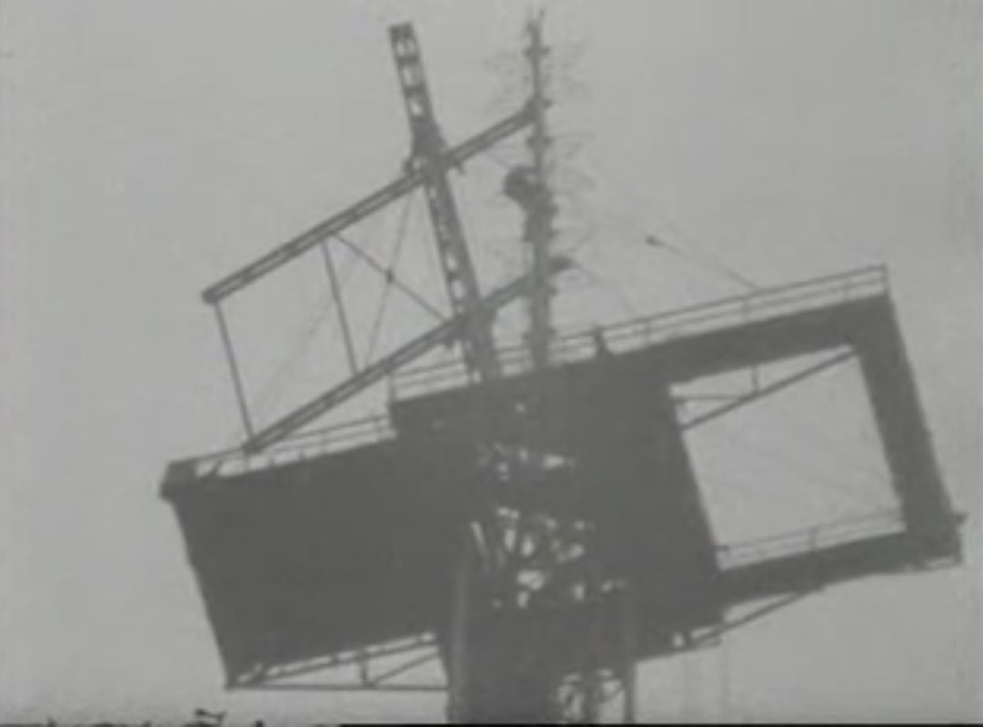
The antenna platform, 200m up in the sky.
|

The shed immediately below the antenna tower, housing the transmitter, the control room and the equipment for the connection to the studio in Bussum.
|
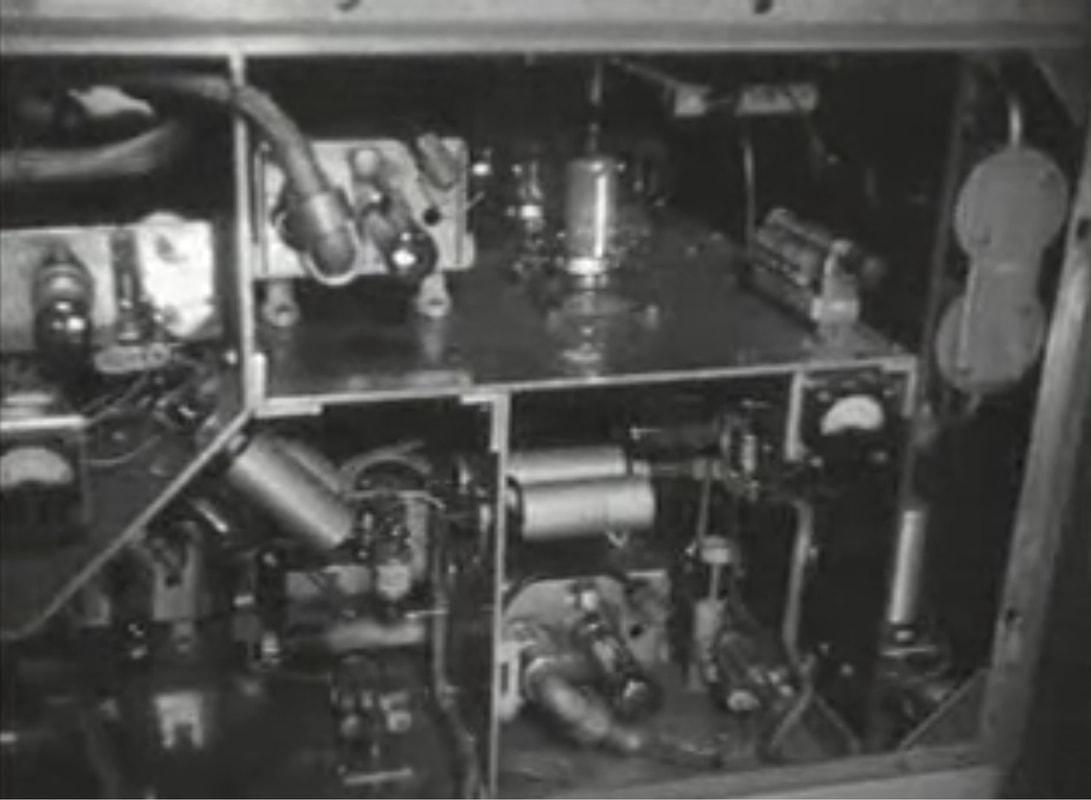
The interior of the transmitter. In combination with the 223m high antenna tower it provided a 65km range, covering all of central Netherlands.
|
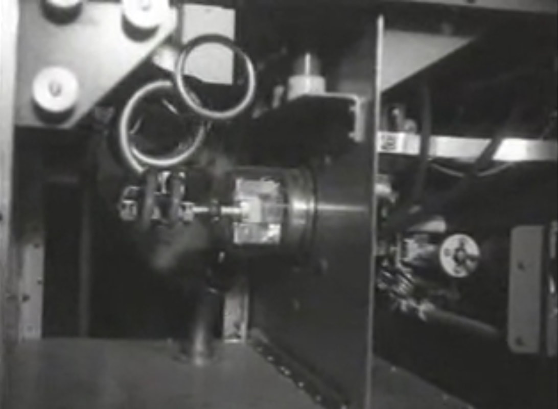
The transmitter valve in the centre, protruding through a metal screen. It is connected to the thick coils of the antenna matching, where the tuning coil in front was mechanically moved up or down.
|
|
After the May 1951 CCIR meeting in Geneva where no consensus on a single standard was achieved, The Netherlands announced it adopted the 625-line "Gerber-standard". However, on May 8 the Dutch government formally announced they would not support and finance the establishment of a BBC-like national broadcasting organization; the private-public broadcasters would have to finance and organize it amongst them. All the government would do was allow the PTT to operate a transmitter at IJsselstein. The broadcasting organizations consequently organised themselves on May 31 in the Nederlandse Televisie Stichting (NTS), which would take care of the programs during the experimental two-year period. And May 1951 was a busy month, because on May 12 experimental - but not yet official - test transmissions were started from the new PTT/Nozema transmitter tower at IJsselstein/Lopik (officially called "Zender bij het Paardenveld") in the centre of The Netherlands, south-west of Utrecht. Here a 223m high lattice tower had been erected, the then highest building in the Netherlands. A shed near the tower housed the transmitter and control room, equipped with a Philips transmitter built by its daughter Nederlandse Seintoestellen Fabrieken (NSF) in Hilversum. Philips also financed a recording studio for the NTS in a former church in Bussum, north-east of Utrecht. In 1950 Philips sent a group of engineers including ir Ton Paling from the NatLab TV group to Bussum, to manage the set-up of the Irene Studio, which officially opened on August 6, 1951 while the first official NTS television program was broadcast on October 2, 1951. In the meantime, on July 10, the PET in Eindhoven made its final transmission after 265 broadcasting sessions. Finally television broadcast had been established in The Netherlands as the first country using the new 625line standard! Western Germany started December 25, 1952, while Belgium (both Flanders and Wallonie) followed October 31, 1953.
|
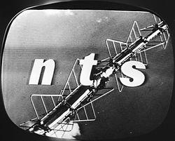
The first transmitted television image of the NTS, October 2, 1951.
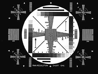
The NTS test image that was used for decades.
|
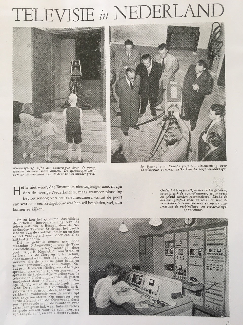
Article from a local newspaper on the opening of the Irene Studio on August 6, 1951. It says: "[...] After prof. Kors had spoken a few words on the official opening, in which he expressed his confidence on the future arrangements around television broadcast, the guests received a guided tour by ir Paling of the NV Philips, who has arranged the studio. The space in this former church is not big, but, as insiders confirm, sufficient for the first period of experimenting. At around a third of the building a wall separates it in two: a large hall with left and right large racks for mounting the lamps, and a smaller room [with the control equipment]". [Archief Edvard Paling]
|
NTS television studio "Irene" in an old church in Bussum. The studio was 100 square meter and had two cameras. [DBNL]
The first program of the NTS on October 2, 1951 was a real party! On the left the priest prof. dr. J. Kors, chairman of the NTS as well as the KRO, on the right Secretary of State for Education, Art and Science Mr J. Cals, a later Prime Minister. It was followed by a brief explanation of the principles of television by Philips engineer N. Halbertsma and a short play called "De Toverspiegel" (the Magic Mirror). [DBNL]
|
TX400 & TX500, the first 625-line Philips TVs, 1951
And so the moment had arrived that for Philips all things came together. A new 625-line standard had been defined, different from those in the existing television countries Britain and France, thus (for the moment) eliminating competition from those countries. And despite the lukewarm government support, the Netherlands was the first country starting television transmissions using this new Gerber-norm standard (today's CCIR-B). Because Philips had secretly decided as early as end of 1948 to put its money on this new standard, first sets had been available second half of 1949; the TX594U in its third and final version. This one had been used to get the infant deceases out of the concept, and in early 1950 the Radiobuizen Lab had issued its 20-valve reference design for a 625-line receiver, based on the brand new Noval generation of valves amongst which a number optimized for television reception (EF80, ECL80, EQ80, PL81 and PY80). This was then the starting point for the formal 625-line first commercial platform, the TX400 and TX500, developed by the Eindhoven Apparaten Lab.
|
The TX400U was designed in 1950. The good relation between Dammers' Radiobuizen Lab group and the Apparaten Lab is shown by the fact that the TX400 design was for 95% identical to the RBL5 platform. There was only a small number of modifications:
|
A beautifully restored TX400U. [Technisch Museum.nl]
|

The line frequency chain of the Philips TX400U. B17 (ECL80) is the synchronization separator, where the line sync pulses will appear as opposite polarity pulses on the secundary windings of output transformer S55 (Fig.7A). Valve B19 (ECL80) is the line frequency oscillator, which requires synchronization with the line sync pulses of the received signal. To that end the line output pulses are tapped off from the line output transformer S60 (Fig.7B). These pulses are fed to a double integrator (R163-C165 and R115-C133) resulting in the triangular voltage of Fig 7C.. This voltage is added to the voltages of Fig.7A, resulting in the two output voltages of the discriminator on R111 and R112 as shown in Fig.7E. These two voltages are peak detected by the two diodes of B18 (EB91) and subtracted, resulting in a control voltage at R148-R117. When the loop is in lock the pulses will coincide with the zero crossing of the triangular signal, the positive and negative pulses will cancel each other, and the resulting control voltage is zero. However, when not in sync the pulses will move up or down the slopes of the triangular voltage and result in a non-zero output voltage at R117 on the control grid of the oscillator, and correct it in the right direction. [Philips TX400U service manual]
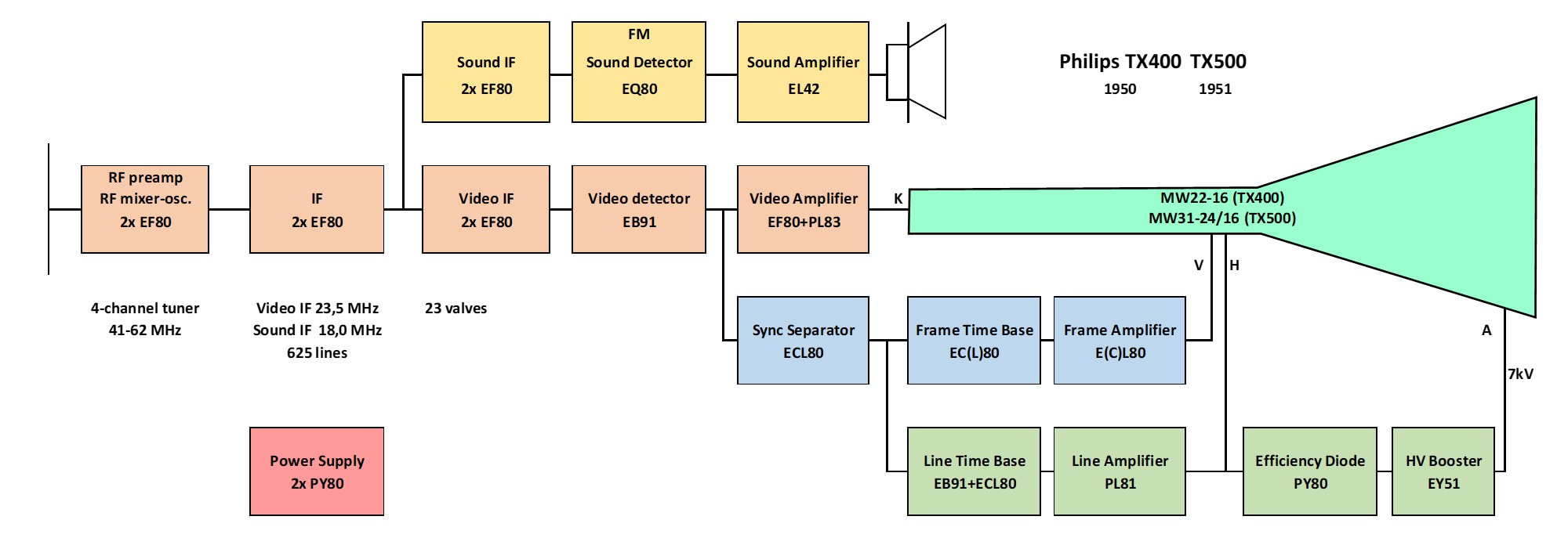
Block diagram of the Philips TX400 and TX500, the first commercial 625-line receivers in Europe and launched in the Netherlands, the first country with 625-line transmissions.
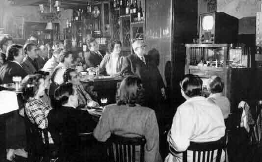
The first sets of the TX400U must have been ready end of 1950. Here we see a small crowd in the pub "Poort van Kleef" on the central market square of Eindhoven during a live transmission on November 10, 1950. The set is clearly a TX400U and not the TX594U. [Philips Archives]
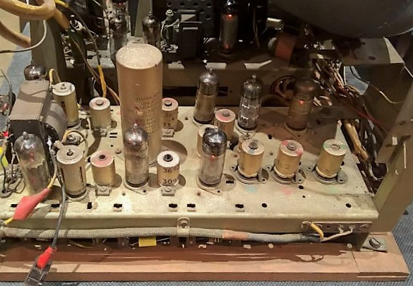
Interior view of the TX500-00. This set introduced the 4-channel tuner, which is visible in the front left corner, with its two EF80 valves on top. [Technisch Museum]
|
Early 1951, synchronized with the NTS transmissions starting in May, the TX400U was finally launched on the Dutch market. This made the TX400 the first commercial 625-line receiver in Europe! The price was around 650Hfl, a considerable amount those days, and sales were consequently modest. Reports by Philips suggested a total of 500 sets sold by the start of the NTS transmissions. Because of the unimaginative level of the programs sales remained modest for quite a while. Only in 1952 with the live coverage of Royal family visits, the funeral of King George in England and the soccer match Belgium-Holland did sales really pick up. By 1953 there were reportedly 12.500 sets in the country. Where the TX594 had received the nick name "Hondje" (Doggie), for reasons unclear to me the TX400 was called "Het Hondehok" (Dogs cage).
Roughly a year after the introduction of the TX400 the TX500 was introduced, which was electrically 100% identical except for the larger 12" MW31-24 non-ion trap picture tube, followed shortly by a version TX500-10 with the MW34-16 ion trap tube. 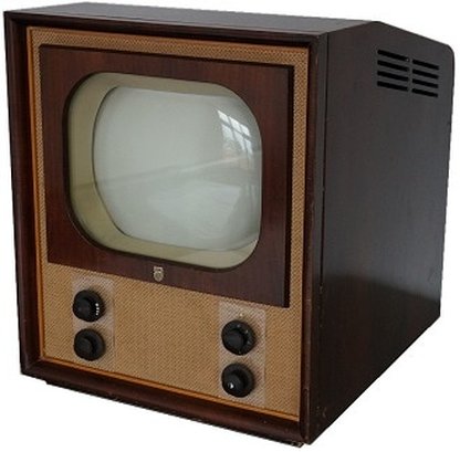
The Philips TX500U, the slightly larger version of the TX400, using the 12" MW34 picture tube. [Technisch Museum]
|
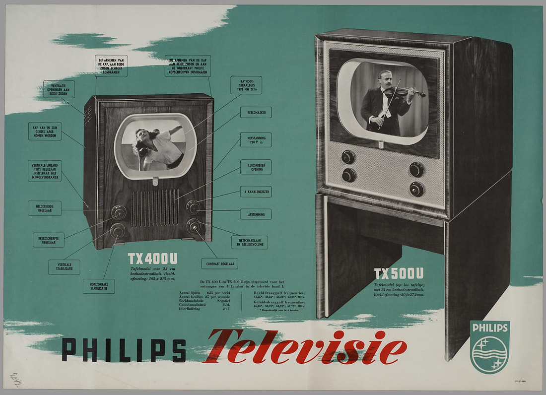
Philips advertisement from 1952 for the TX400 and TX500 sets. [Geheugen van Nederland]
|
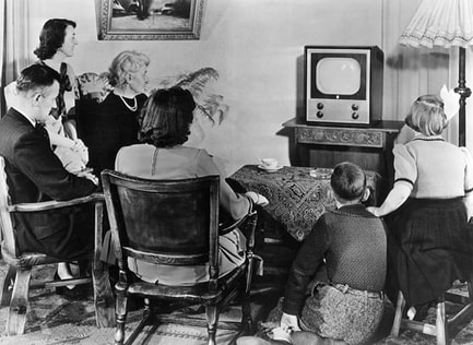
A new family pass-time, watching TV. In this case a Philips TX500. [Pinterest]
|
|
Although the TX500U and TX400U were nominally the identical electrically, there was one major difference: the TX500-oo basic model introduced the tuner! Although the CCIR had not succeeded in converging on a single television standard for all of Europe, it did establish the Gerber-norm for most of Western Europe (except Britain and France) including standardized channel frequencies. For VHF-I these were (picture carrier) 41,25MHz (Ch.1), 48,25MHz (Ch.2), 55,25MHz (Ch.3) and 62,25MHz (Ch.4). Whereas all receive sets up to now had been designed for a single pre-fixed reception frequency, with a tuner multiple channels can be received. The concept used for the very first 4-channel tuner was capacitive tuning, using fixed coils in combination with a variable capacitor.
|
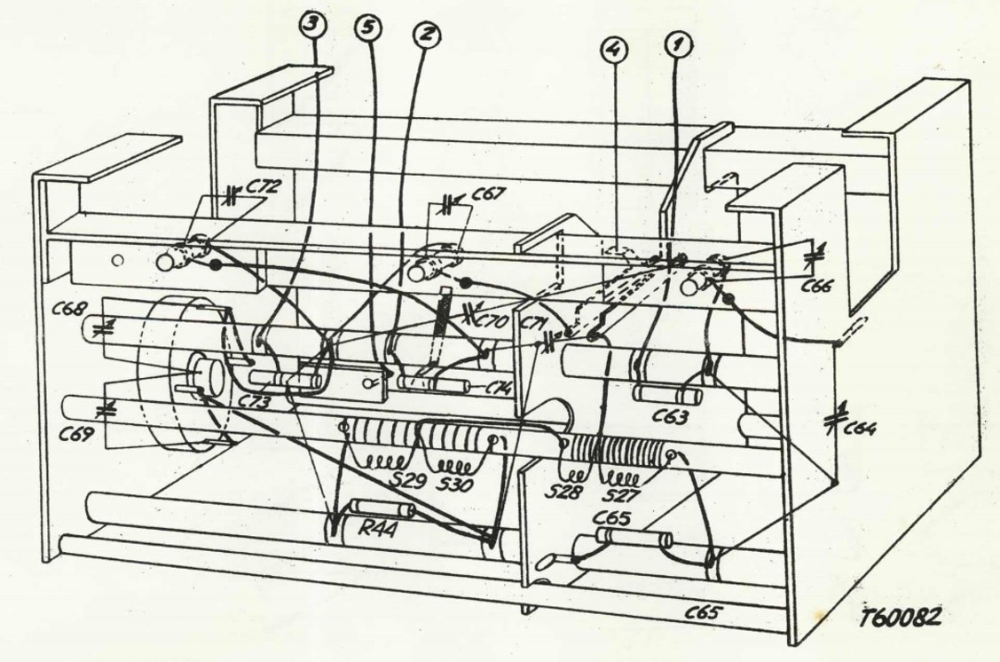
Mechanical view of the 4-channel VHF-I tuner of the TX400U-04 and TX500U-04 versions. The inductors S27-S30 are tuned by the variable capacitors C64, C70 and C71. [TX400/500-04 service manual]
|
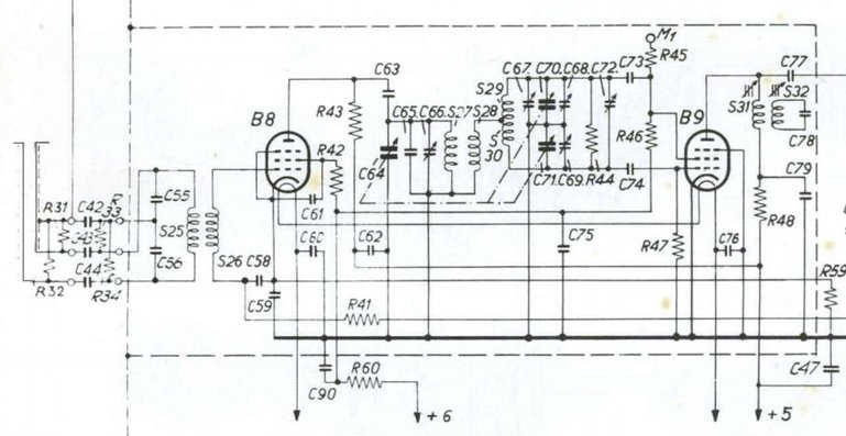
Circuit diagram of the 4-channel 300 Ohm input tuner of the TX400/500U-04. The inductors S27-S28 of the bandpass filter and S29-S30 of the oscillator would be changed for each channel. The variable capacitors C64-C70-C71 would be simultaneously tuned for optimum channel reception. [TX400U-04 Service Manual]
|
Because the TX400 and 500 sets were very expensive at the time they were kept in use for multiple years, in the meantime often receiving upgrades. A first example was the introduction of the 4-channel VHF-I tuner, which was a service upgrade for the TX400 but standard in the TX500 when launched. Later both chassis could be upgraded with the 10-channel VHF-I plus -III tuner when that was launched in 1952. Similarly sets could receive the ion trap picture tube MW31-16.
Outside The Netherlands the TX400 platform was only used in the UK where, adapted to 405 lines and AM sound, it became the 1000-series. The first were the 1100, 1101 table models and 1200 console, all equipped with the MW31-16 picture tube of the TX500. All models had the 5-channel tuner adapted to the British frequency plan with its 5MHz channel width. By 1952 the upgraded 1114U and 1115U appeared, with the larger 14" MW36-24 picture tube. Of all British sets there were, next to the basic U version (for Universal power supply, i.e. AC and DC), also so-called UF "Fringe versions" with adapted sensitivity setting for reception at the outer limits of the transmitter range. The platform was apparently very successful, because it continued into 1952 (12" 1229U, 14" 1427U and introducing the 1726U with the latest 17" MW43-64 picture tube), 1953 (1236U and 1437U) and even 1954 (1446, 1746-48). Who would have thought that based on the same design as the TX400 with its tiny 9" tube within four years sets with an almost four times larger screen could be made? Because the UK chassis was running for such a long time it received some intermediate upgrades, especially the introduction of the 12-channel tuner in the 1954 models, linked to the introduction of VHF-III in 1955. However, most versions remained single band, but could be upgraded with an internal or external tuner. For details see the tuner history. Note that all these TVs, including the first AT7520 UK tuner, all continued to use the by this time very low 12MHz VIF 8,5MHz SIF. It is still not clear why the UK Philips/Mullard TV design organisation was so conservative, given that most competition but also internally the Dutch/German and French sets had moved up in IF for three years already. Only the 1955 platform would, forced by the UK BREMA standardization and the introduction of VHF-III transmissions see the move to the official 34,65MHz VIF38,15MHz SIF. |
The small-signal panel of the Philips 1200U. This chassis still didn't feature a tuner, but introduced an easier way to change a set for either London or Birmingham reception. To this end the three filter modules in the lower right corner, with the colour markings, could be exchanged. [UK Vintage Radio Repair Forum]
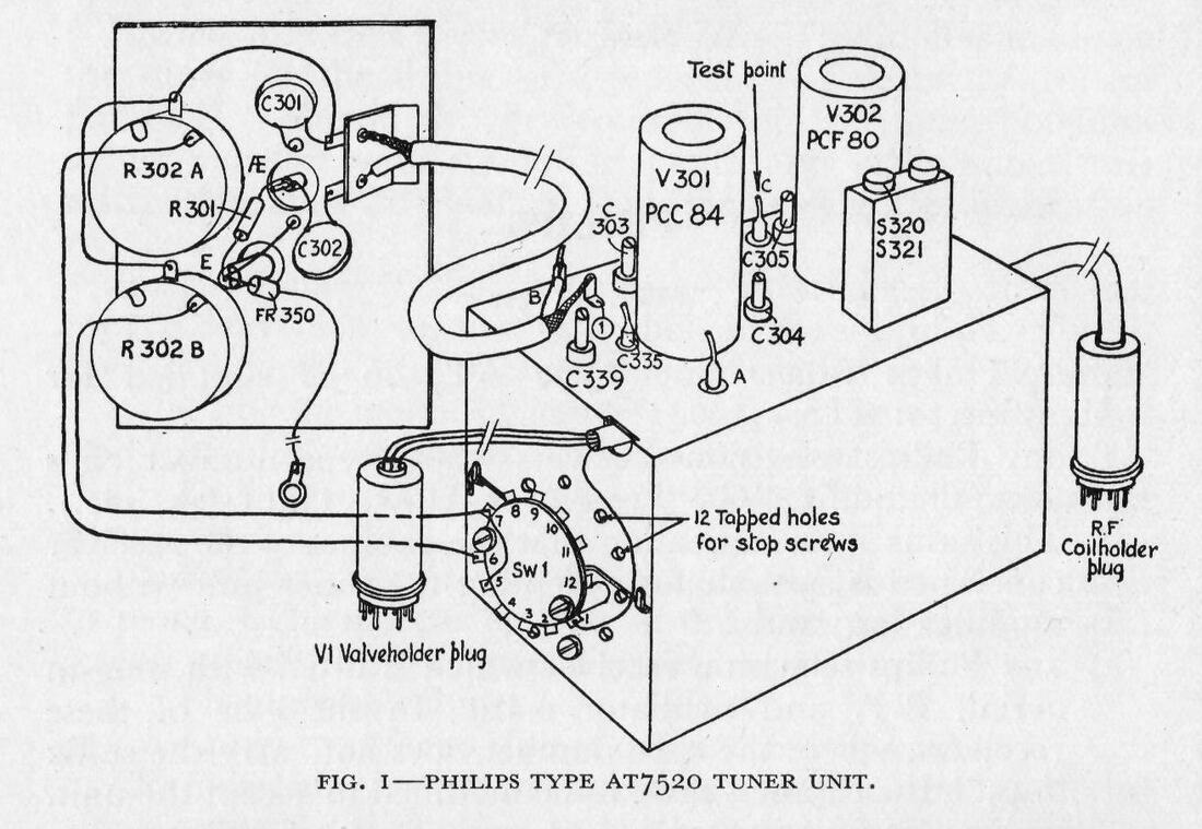
An AT7521 retrofit tuner module, to upgrade a UK TV set from one to 12 channel reception. The left plug was inserted in the original EF80 pre-amp socket, the right plug into the RF filter socket. Switch1/2 in combination with R302A/B allowed separate sensitivity setting for Band-I and III. ["TV conversion for I.T.A."by CE Lotcho, 1957, Jac Jansen collection]
|
The Philips 1100U 405-line TV set for the British market. This was the equivalent of the TX500 with a 12" MW31-16 ion trap picture tube. [Philips Service Manual and The Valve Page]
|
The Philips 1446U with the 14" MW36-24 picture tube. [The Valve Page]
|
The Philips 1748U from 1954, with the new 17" MW43-64 tube. [Philips Service Manual and TheValvePage.com]
|
The last come-back of Protelgram, 1950-1952
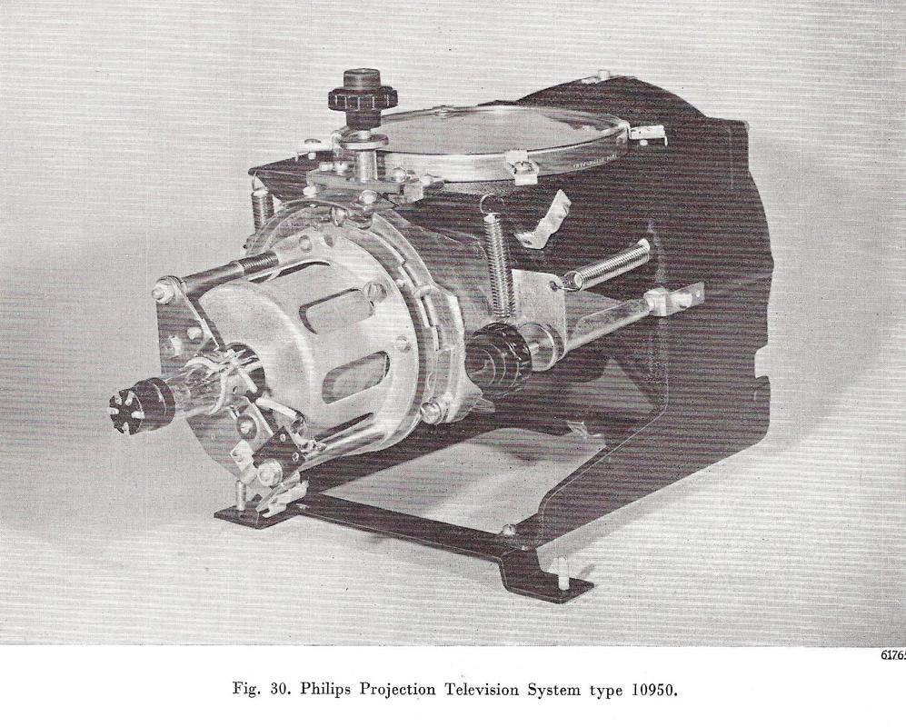
Picture of the Protelgram projection television optics as used in the TX600 and TX700 platforms. [EAB April 1950]
|
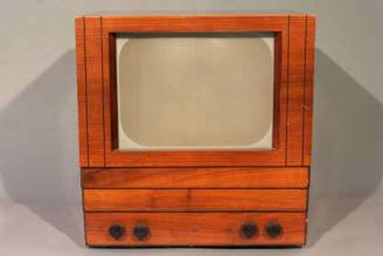
However incredible it may seem after the massive and costly failure in the US, but in 1950 Protelgram made its come-back in Europe! It is unclear whether this was due to a.) real believers and supporters inside the Philips management, b.) the need or desire to recover some of the investments and use the undoubtedly massive stocks of modules, c.) a desperate marketing move to come with larger screen sizes not yet possible with picture tubes or d.) the continuation of developments started (much) earlier under a global Protelgram policy. Apparently there were some real supporters in the HIG Apparaten and especially its sales organization in the UK. Another indication that Protelgram was not dead were three articles in the 1950 Electronic Application Bulletin with extensive explanations of the principles of rear projection optics. So whatever the (combined) reasons, in 1950 the company launched the TX600 platform, a derivative of the TX390. Two almost identical implementations were developed: the TX601A/29 for the French 441-line market, and the 600A for the British 405-line market. The year before, at the 1949 RadiOlympia show in London, the 799U was demonstrated, but it seems this set was never taken into production.
|
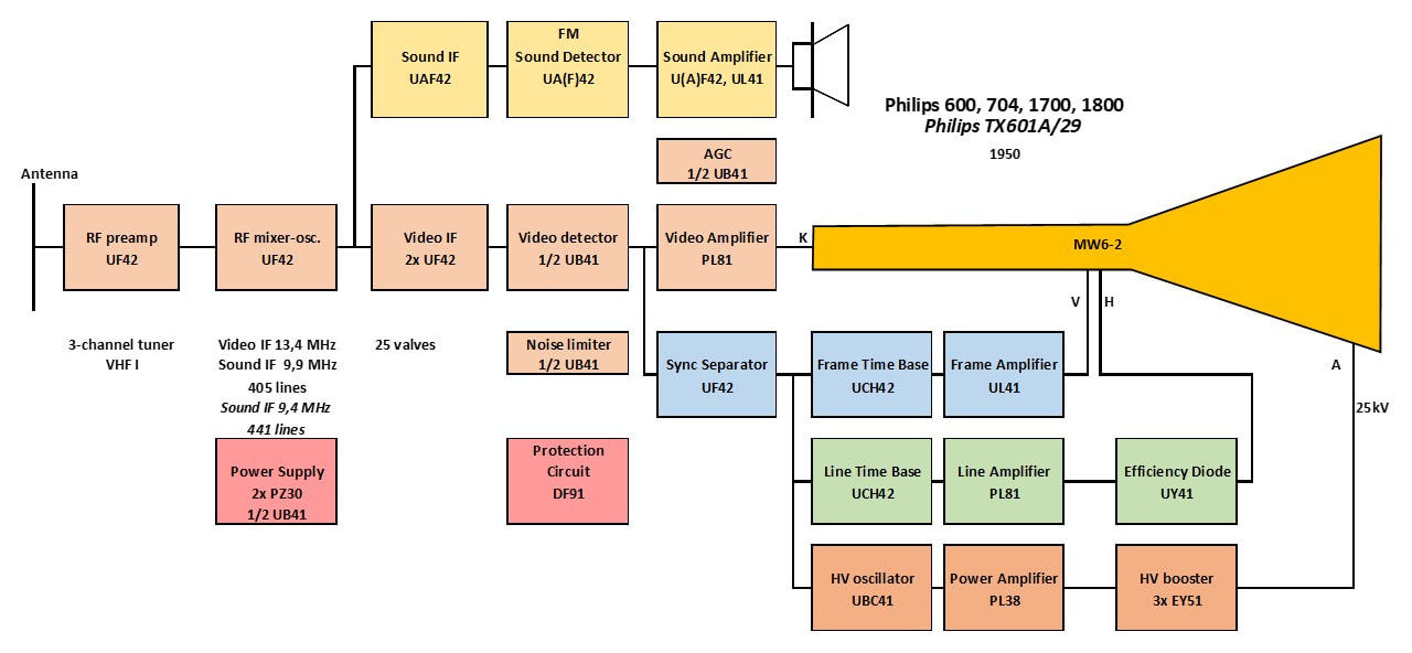
Block diagram of the Philips TX600, the first Protelgram-based rear projection TV launched in Europe. It was produced in British (405 lines TX600) and French (441 lines TX601) versions.
|
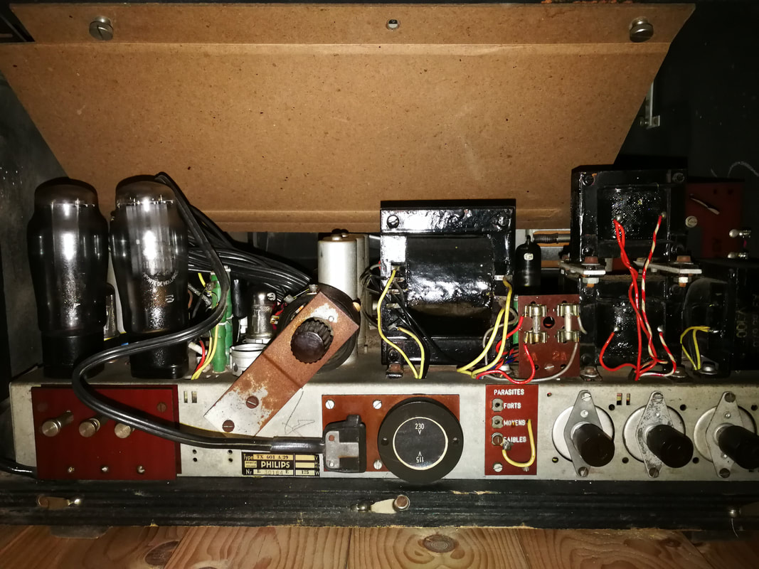
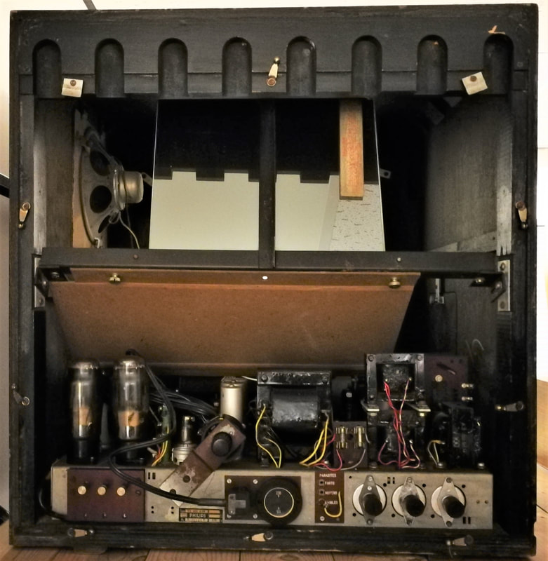
Backside interior view of the Philips TX601/29 rear projection TV. Ledt the full view, with centrally the mirror, right a close up of the frame. [via Taco Vonk]
|
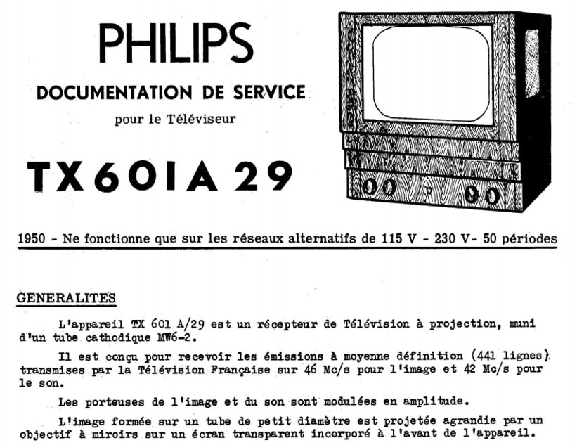
The rear projection TV TX601A/29 for the French 441-line standard, 1950. [Antique-TV-Blazianu]
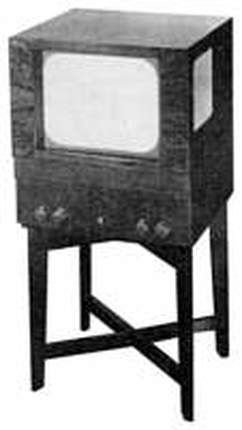
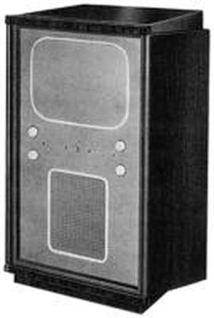
The TX600 platform was developed by the Apparaten Lab, but implemented in only two versions. The first was the French TX601A/29, as the product code indicates produced in Eindhoven (the X) but intended for export to France (the suffix 29). The British implementation appeared in a number of variants, suggesting it sold fairly well. The first was the 600A, almost certainly identical to the basic platform. It looked identical to the TX601A and was sold with an optional stand at the price of 2 GBP 15. The next year, 1951, three more versions appeared: the 1400, 1700 and 1800 families. These were the last projection television sets Philips would launch in the UK. They were soon to be be replaced by picture tubes of similar size. In parallel the Protelgram module was also sold to other set makers, like Decca in the UK, which brought out the Protelgram models 131, 121 and 1000. In these models Decca only used the Schmidt optical module including the MW6-2, all other set design was independent of Philips.
|
The TX600 platform, which was only developed for AM-based standards, used 25 valves; 19 for the regular TX390-based TV-chassis, five for the separate 25kV High Voltage supply unit plus the (already 5 year old) MW6-2 high brightness projection picture tube. Because of the high brightness the tube was pushed to its limits, and any fault in the drive voltages - e.g. in the case of the vertical raster scanning voltage falling away only a thin horizontal line would be displayed - resulted in burn-in of the picture tube phosphors, requiring replacement of the tube. A separate protection circuit was thus built-in, which immediately switched off the MW6-2 supply in case of such events. The optical module was still 100% identical to the one used in the SG860/SX861 NatLab prototypes as well as the Protelgram module sold in the US. Via a large 45degrees mirror the image was projected on the back of a thin plastic Fresnel-lens. This lens focused the light in the direction orthogonal to the lens to re-gain some brightness, although that remained lower than from a regular picture tube. Furthermore it limited the angle under which the screen could be viewed, and the projection sets could not be used in larger rooms, which was quite a drawback.
Modified Philips Television coding scheme 1951-1953
Starting from mid 1951 the Philips Television coding scheme slightly changed. For example TD1410U. So far the first digit (the hundreds) indicated the luxury level of the set. This was a not well defined parameter, however, and by this time it was clear that screen size was the most determining feature, more than the cabinet size. The coding thus became as follows: 1st letter: T for Television, C for Console 2nd letter: country code, unchanged (F, (G), X) 1st and 2nd digit: screen size in inches; in most cases these were thus TWO numbers (14, 17, 21, 23 etc.) 3rd digit: last digit of year of release, unchanged 4th digit: serial number within a family but also indication of luxury level; console types usually 7-8-9. Suffix letter: A for Alternating Current only, U for Universal supply, both AC and DC |
|
|
|
From left to right the 600A, 1400A and 1800A projection TV sets. The 600A is of the same design as the TX601A-29, here shown with the optional stand. The 1400, 1700 and 1800 all looked the same apart from style details. The right picture shows the inside of the 1800A with in the centre behind the chassis the main mirror and in white the back side of the projection screen. [All pictures from The Valve Page.com.]
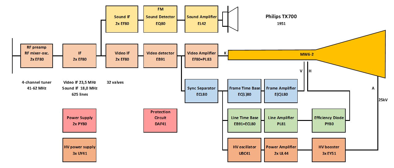
The Philips TX700 block diagram. This set was a rear projection derivative of the TX400 platform.
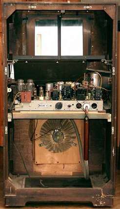
The French and British projection TVs above could be released fairly quickly based on the existing regular 405 and 441 line sets. The 625-line projection TV had to wait for a solid platform for that new standard, and the TX701A as it was called thus saw the light after the TX400/TX500 launch in 1950/51. Conceptually it was identical to the previous ones: a standard (TX500) chassis in combination with the MW6-2 inside a Schmidt optics module and a dedicated 25kV high voltage generator. The main difference was the latter module. In the TX600 the power supply for the HV module could still be derived from the basic chassis, in the TX700 there was no more head room for the additional valves and the HV module thus had its own power supply of three UY41's. Together with a second line output driver UL44 this made it a nine-valve HV module, bringing the total valve count to a (then) record 32. Two more Protelgram rear-projection display models were to be launched: the German sets TD1714 and TD2314. But these were the last, because, as we will see next, picture tubes were rapidly becoming as large as the rear-display screen. Still ... Protelgram was not dead, and we will see it back later!
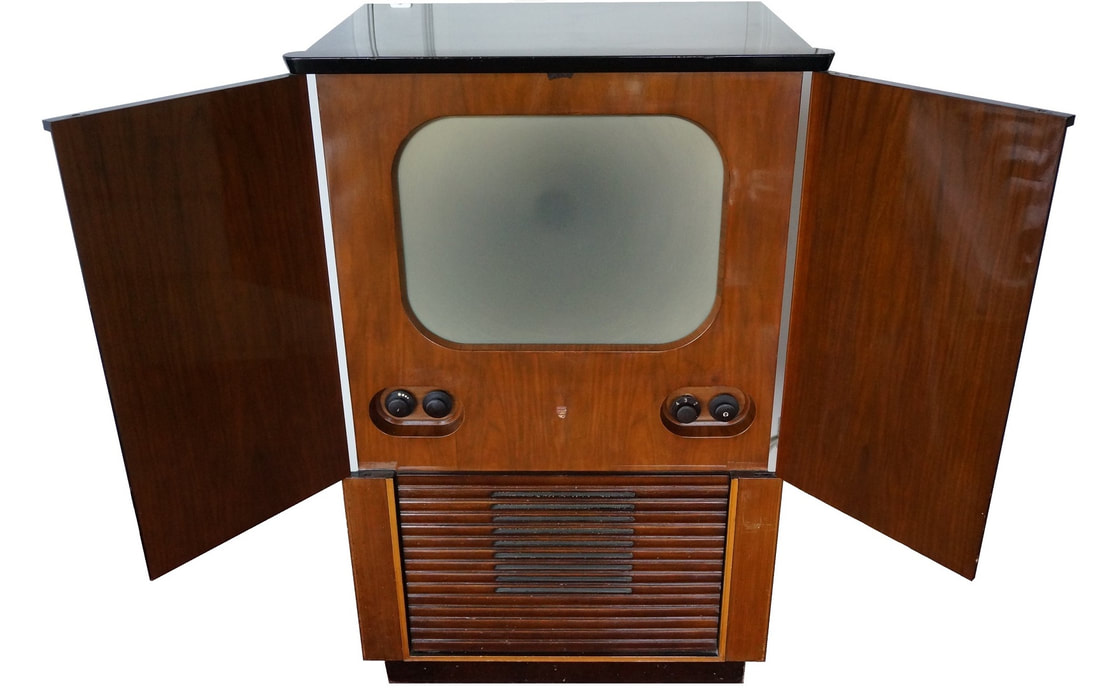
Exterior view of the beautifully restored Philips TX701A rear projection TV from 1951. [All pictures Ronald Huisman Technisch Museum.nl]
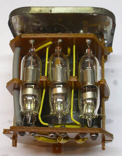
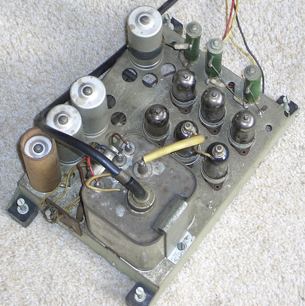
The three EY51 HV rectifiers as mounted inside the HV can. Note the absence of a valve footer. Wires coming out of the valve are directly soldered.
|
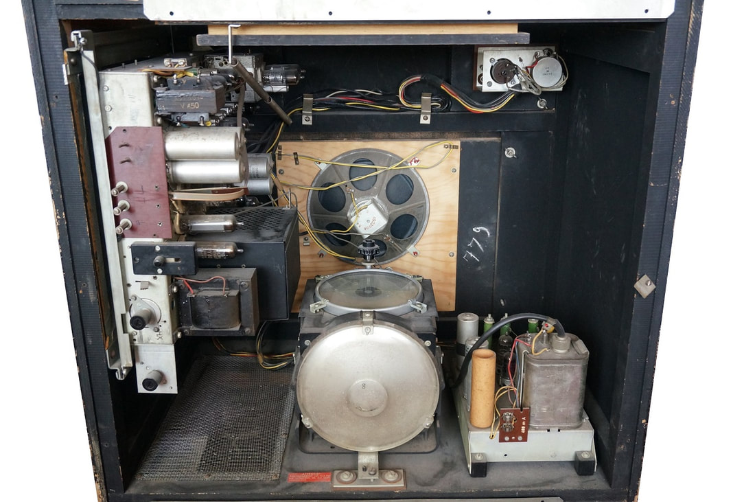
Interior view of the lower section of the TX701A. Vertically against the side on the left is the main chassis, in the centre the optical module and lower right the 25kV module.
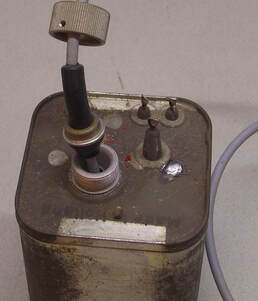
The high voltage tin can, containing the HV transformer and the three EY51's. It is filled with oil and soldered. Note that this is still the same concept as used in Piet's self-built TV from 1947!
|
The 25kV high voltage supply module of the TX701A. In front is the closed oil-filled tin can containing the HV transformer and the three EY51 rectifiers.
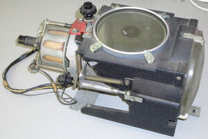
The Protelgram Schmidt optics module with the MW6-2.
|
New picture tubes and factories
|
Despite all brave efforts to re-launch Protelgram and rear projection TV, the concept was doomed. Developments of the picture tube simply went much faster. Especially in the United States RCA was well advanced in creating ever larger displays. So far the picture tubes were designed and produced by the valve organization, the HIG Elektronenbuizen. But picture tubes were quite different from regular radio valves, they were essentially made from two pieces of glass. First there was the cone, into which the electron gun assembly was mounted. On later models the cone was first covered by a metal coating on the outside. This cone was then melted onto the as flat as possible picture screen, which was coated on the inside with a phosphor layer that converted the electron beam into light. With increasing screen width the screen thickness increased too, for supporting the larger pressure when the tube was drawn vacuum. This required a different production method than the classical "blowing" of glass tubes, but instead a kind of pressed moulding of hot glass. It also required different types of glass. By 1950 it was clear that Philips did not have any factory capable of this production step for high volumes. Especially in the UK the Mullard fab purchased pre-fabricated cones and screens from external suppliers - and I suspect also complete picture tubes from RCA - but it was clear this was not a viable solution when volumes were to increase. In Eindhoven a small picture tube production facility was established in building SAN on the Strijp-S complex, next to the television factory in building SK.
|
The small scale picture tube production facility in building SAN on the Strijp-S complex. These are most probably MW31-16 12" tubes for the TX500 family. [Beeldbuisboek.nl]
|
Early 1950 a major discussion took place in the Philips management about the need for investments in a picture tube production capability. As said, the HIG Apparaten was not a big supporter, given their simultaneous support of Protelgram rear projection TV as well as their fab purchasing the cones from thirds. The HIG Elektronenbuizen on the contrary, through its technical manager ir Hazeu, was an ardent supporter, mainly because they expected other set makers would first select their picture tube vendor and then buy the remaining valves from the same supplier. In other words they feared the dominant radio valve position of Philips would be threatened in case Philips could not supply the picture tube. This argument convinced the board, and 26MioHfl was made available for the construction of a glass factory and a picture tube factory. Then a another discussion started about the location, where president Otten and board member Frits Philips foresaw serious personnel issues on the already strained Eindhoven labour market, and thus proposed a location somewhere else. This time it was mainly Tromp, again supported by Hazeu, who argued in favour of Eindhoven based on the need to be close to the central laboratories as well as the Apparaten factory. He promised to relax the pressure on the labour market by transferring major radio valve production facilities from Eindhoven to Sittard and Heerlen. Again the board was swayed to vote in support of this proposal.
However, things didn't go as fast as planned. To start, the glass factory would be under a different HIG Glas than the picture tube factory of the HIG Elektronenbuizen. And the latter would not start before the glass factory was well under way. But the HIG Glas was overloaded due to extensions of its lamp and TL factories, and work on the glass factory delayed. In 1951 the Philips board reconfirmed its priority, however, and by 1953 the glass factory opened on the new large industrial complex Strijp-R in building RU. A year later the picture tube factory was opened next door in building RAD, while a large laboratory for picture tube development was opened in building RAF.
However, things didn't go as fast as planned. To start, the glass factory would be under a different HIG Glas than the picture tube factory of the HIG Elektronenbuizen. And the latter would not start before the glass factory was well under way. But the HIG Glas was overloaded due to extensions of its lamp and TL factories, and work on the glass factory delayed. In 1951 the Philips board reconfirmed its priority, however, and by 1953 the glass factory opened on the new large industrial complex Strijp-R in building RU. A year later the picture tube factory was opened next door in building RAD, while a large laboratory for picture tube development was opened in building RAF.
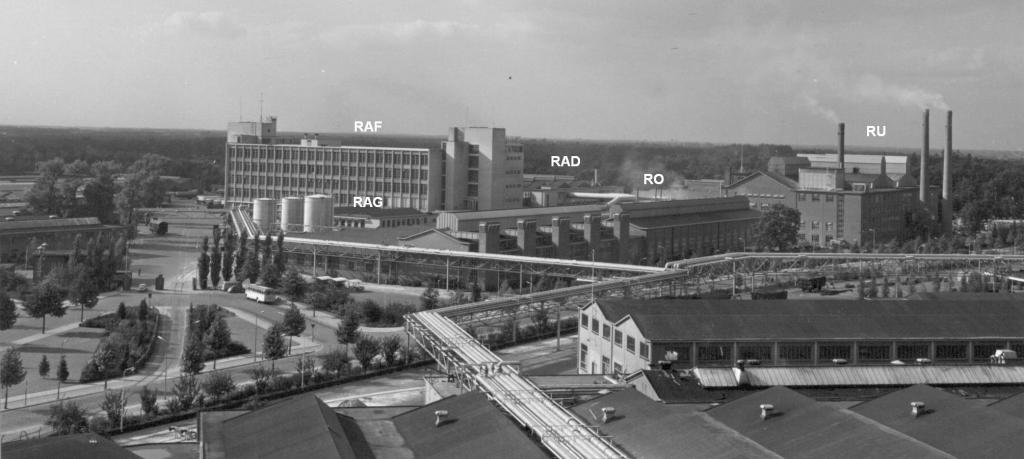
Philips complex Strijp-R in Eindhoven. RU is the glass factory, while RAD is the picture tube factory. RAF is the picture tube development lab. [Fabriekofiel.com]
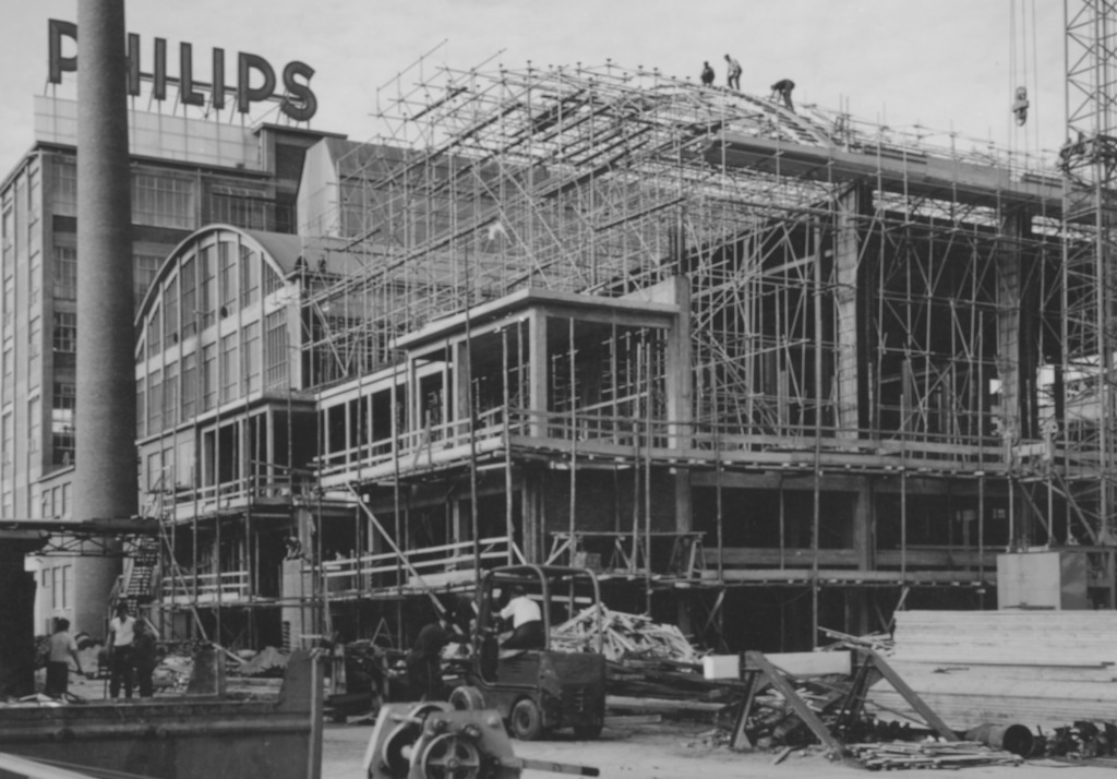
Construction of the large glass and picture tube factory "Rote Erde" in Aachen, Germany during 1953. Tubes from this factory were used in the nearby Krefeld television factory. [Fabriekofiel.com]
|
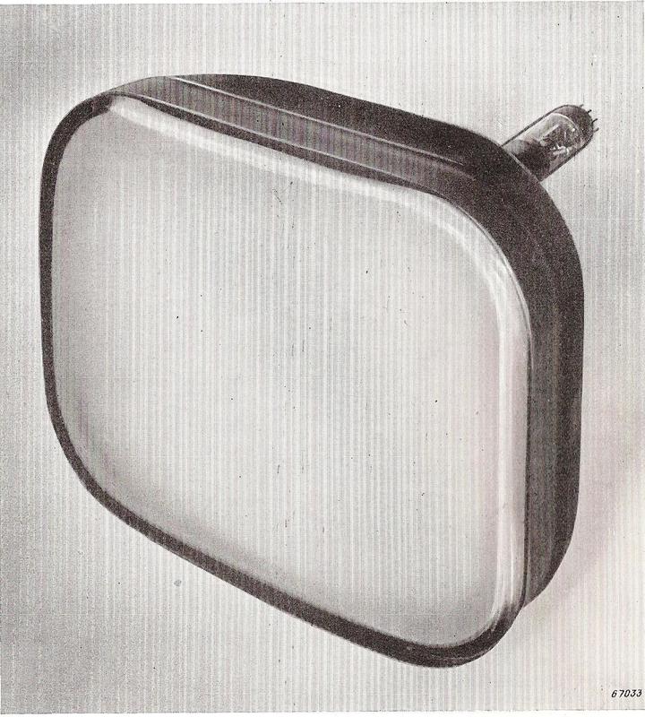
The new square picture tube MW36-22 with a diagonal of 14". It was launched in 1951 and used in the new TX1410 platform. It would soon be followed by the MW43 (17") and MW53 (21"). [EAB 1951]
|
Early picture tube production, probably in the new Strijp-R factory. The tube looks like a square 21" MW53. [Ronald Dekker]
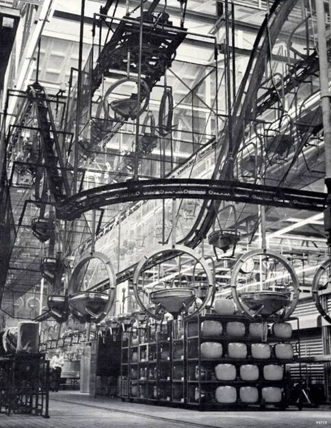
The picture tube factories quickly became bigger. Here the Aachen factory in full production, showing the transport system for the 21" picture tubes. [PTR 1958]
|
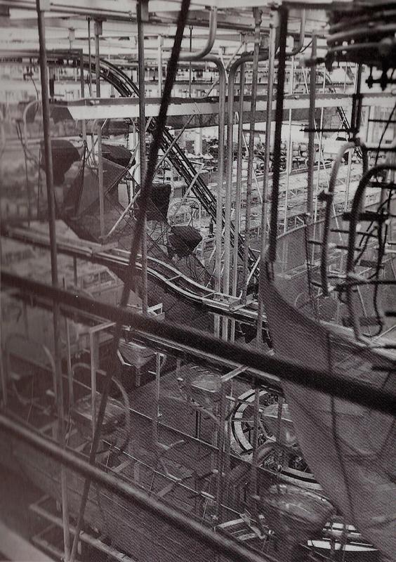
The new highly automated picture tube production line in the new Strijp-R factory, 1955. [Geschiedenis Koninklijke Philips -pt.V]
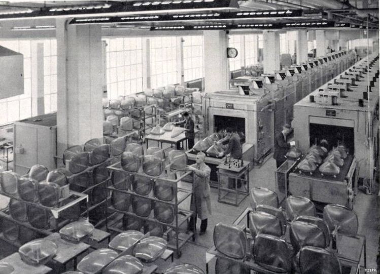
To take the stress out of the picture tube after the glass screen and metal cone had been connected, the half-finished assemblies passed through a long annealing oven, here seen in the new StrijpR picture tube factory. [PTR 1957]
|
By 1952 it was entirely clear that the picture tube was the winning concept, and the Philips board decided for an accelerated program to establish the company's own picture tube capability, where a market share of 60% was targeted in Europe. To that end the construction of three more factories was ordered: in Aachen (Germany), Simonstone (UK) and Dreux (France), which would all open between 1955 and 1957. In the meantime picture tube development had also accelerate. Where the first generation tubes MW22 (9") and MW31 (12") had been circular, with the 14" MW36 much more rectangular screens were introduced. This was the product that would soon run in ever increasing volumes in the new picture tube factories, steadily increasing in size to 17" (MW43), MW53 (21") and MW59 (23").
The Television factories
Parallel to the picture tube discussions similar ones took place around the television factories, although with a different tone. The continuing growth of the Philips radio business (almost 2 Million pieces in 1952) and the emergence of the television business (some 200.000 sets in that same year) revealed an important difference with the more traditional component business like lamps and radio valves: the use of capital. The large component stocks as well as the stocks of finished products demanded a dis-proportional amount of working capital at a moment that the company desperately needed money to invest in new factories. So whereas the Philips board invested heavily in the new glass and picture tube factories for television, the HIG Apparaten was told to cut back its stocks and spending. One of the directives was that traditionally quite independent fabs should not be allowed to select components themselves, but that platforms should be harmonized and components standardized. The existing Apparaten factories in Eindhoven Strijp-S, Mitcham (Mullard in the UK), Suresnes (France) and Monza (Italy) should essentially support the required growth from their own budgets. [Is is clear that management decisions were not fundamentally different then from now!]
|
|
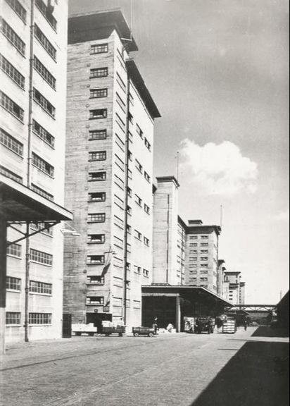
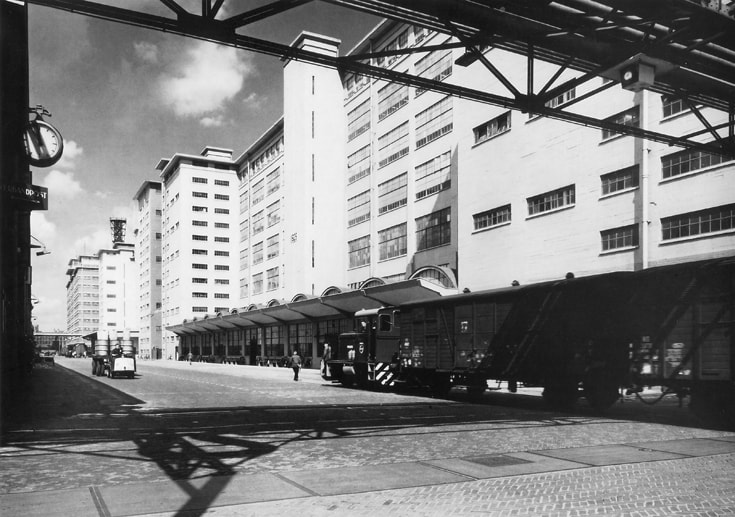
The Apparatenfabriek (set factory) of Philips on the Strijp-S complex. These were built in 1929, heavily damaged by the December 1942 RAF bombing, but quickly rebuilt. They consisted of three almost identical, interconnected buildings. From east to west SK, SAN and SBP. Television production was in SK, with initial picture tube production in SAN. [Eindhoven in Beeld]
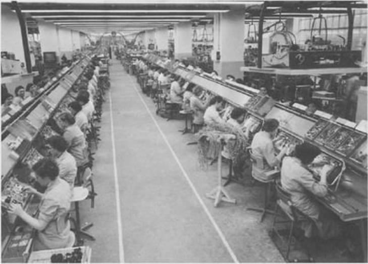
Interior view of the television production line of the Apparaten-fabriek in building SK, with the typical low ceiling and concrete pillars. The picture was taken in 1956. [DBNL]
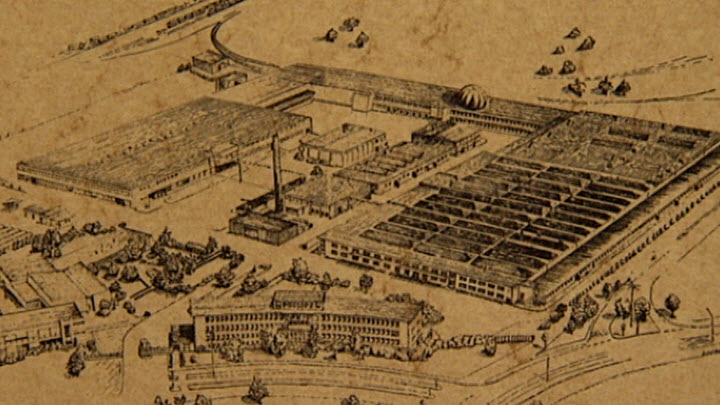
Impression of the Krefeld television factory after completion. On the right the oldest part, Halls 1-3. On the left Halls 4-5 where sub-assemblies and tuners were produced. In the front the curved main building. In its heydays the fab employed 3250 people.
|
The one exception to this was Krefeld, in Germany. This served the dual role of off-loading the production from Eindhoven, while it was to serve the large German market once that would start in 1952. Between the city of Krefeld and the River Rhine, near the old township of Linn, a 7,5ha factory was built. It opened in 1951, expanding to three production halls with 500 employees by 1954. During the following three decades it would become one of the largest set manufacturing sites of Philips.
|
New features, the TX1410 platform 1952-55
he original TX400 platform, from which the TX400, TX500 and the UK 1100 and 1200 families had been derived was still a very basic design, mainly to keep the introduction cost low. It offered the basic TV function without any features, in fairly small cabinets due to the small picture tubes. The first generation TVs were still large wooden boxes with a fairly small screen. So as a next steps two first developments can be seen: larger screens and first features. At the same time it should be admitted that the electrical performance of the TX400 platform was good, since based on by then five years and three generations TV development in both the Apparaten Lab and Radiobuizen Lab. So the next step, the TX1410 platform, was still firmly based on the TX400 with only a few modest electrical modifications. These were:
- introduction of the 10-channel drum tuner, covering usually VHF-I channel 2 to VHF-III channel 11 (213MHz)
- switchable Automatic Gain Control between "normal" and "weak stations" (the UK "Fringe receiver" feature). For weak stations the AGC to the RF input amplifier is disconnected and this valve is put in maximum gain mode.
- the possibility to receive FM radio in the 88-104MHz range. In this mode the picture receiver power supply would be cut off.
- balanced audio amplifier with two ECL80's, giving more output power and the capability to drive two speakers
- audio tone control
- external focus control (knob on the back panel) that could adjust the focus magnets through a Bowden-cable.
- larger and rectangular 14" MW36-22 picture tube, later succeeded by the MW34-24 with "grey glass" for higher contrast.
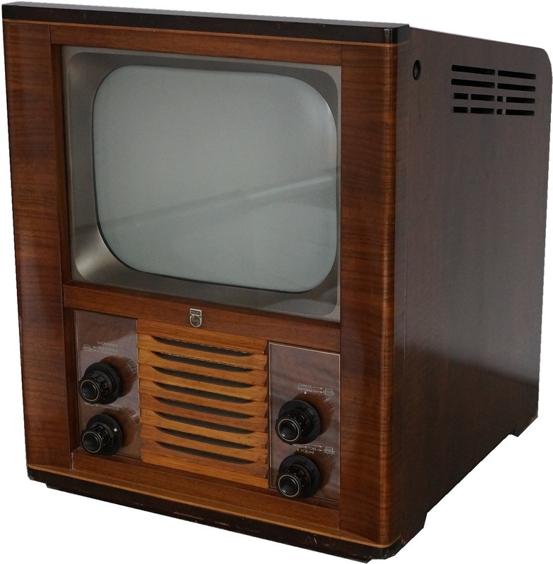
Another beautifully restored TV, the TX1410U by Roland Huisman. The glass plates behind the knobs are clearly visible. It also shows the first rectangular screen after the first generation round screens. [Technisch Museum.nl]
|
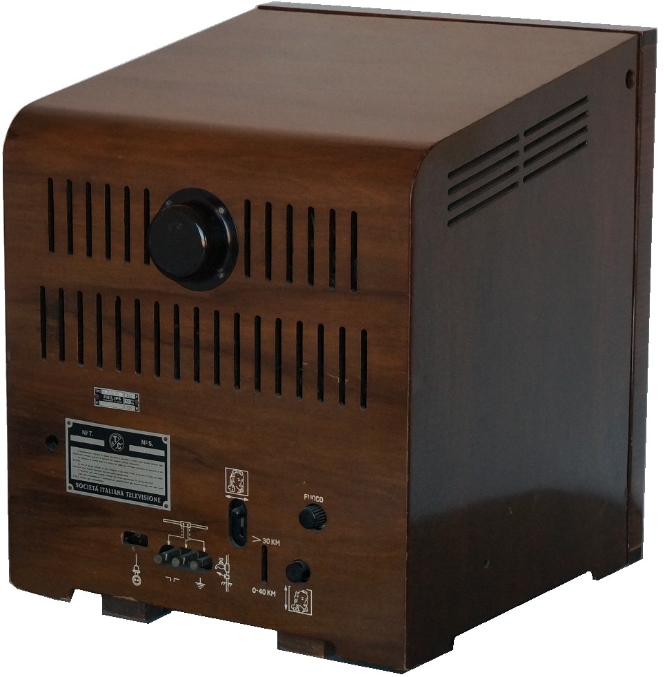
The TX1410U was a luxury model, so even the back side of the set was made from shining wood, making it one of the few TV's that's also beautiful from this side. On the lower right the focus knob as well as the range switch are visible. [Technisch Museum.nl]
|
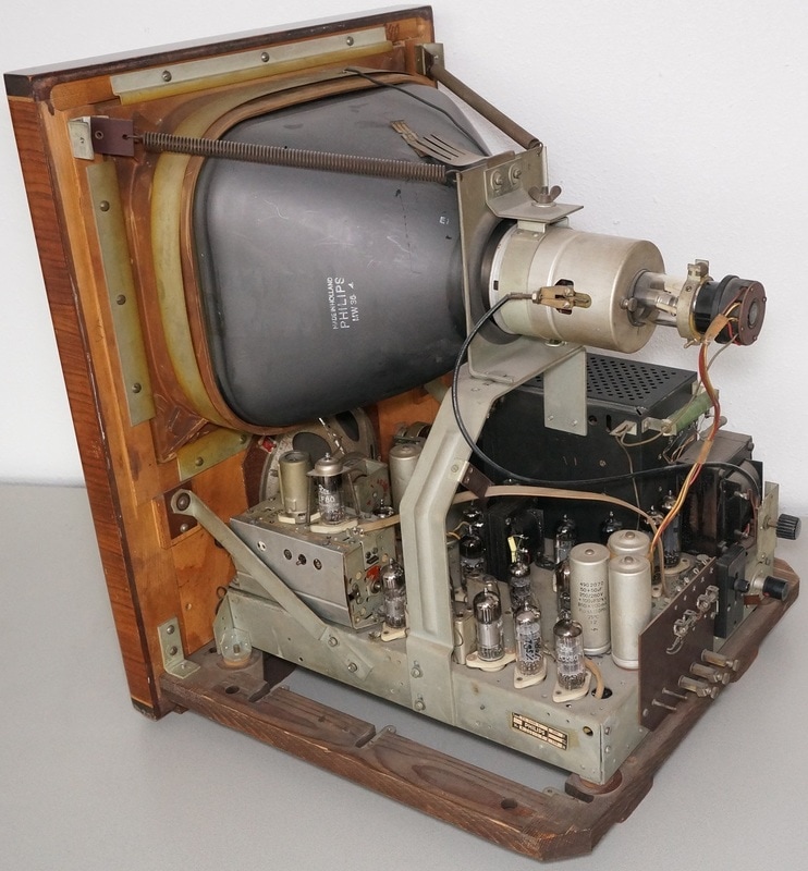
|
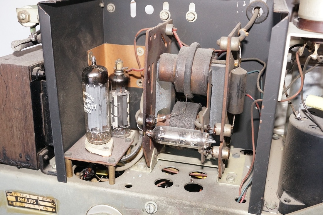
Left the TX1410U with removed cover. Left front the drum tuner, right front the (left to right) EQ80 and two ECL80 balanced audio amplifiers.
Above a view inside the high voltage and line output module after removal of the protective cover. On the left the PY80 booster diode and PL81 (with top contact) line output amplifier. On the right the line output trafo with horizontally the EY51 HV rectifier. [Technisch Museum.nl]
|

The block diagram of the Philips TX1410U. Apart from the introduction of the ECC81 dual-triode in the tuner module, the valves were identical to those of the TX400/500. The only exception is the EB41 dual diode, where for unknown reasons the platform switched back from the newer and smaller EB91 to the EB41. This was the first family also produced in the brand new Krefeld factory in Germany.
Interestingly, the German version of the platform, the TD1410U, seems to have been launched earlier than the Dutch/global version TX1410U. Although it is sometimes suggested this means that the TD/TX1410U was a German design, I don't believe this. The new factory in Krefeld, Germany, was only opened towards the end of 1951, and had at that moment only a still modest production staff of 500 people. The 1 in the TD1410 product code means that the design was ready and released in 1951, which can not have been done in Krefeld. So this was still a platform designed in Eindhoven, which is also confirmed by the high re-use of the TX400 platform. But apparently the planned launch of television in Germany in 1952 required the TD1410U to be launched first. It would in any case become the most widely used instantiation of the platform. Quickly different cabinet versions appeared as the TD1415, 1417 and 1419, all using the same electrical platform.

The new 10-channel AT7501 VHF-I and -III tuner based on the EF80 as low noise pre-amplifier and the ECC81 as oscillator (right triode) and mixed (left triode). [TX1410 Service Manual]
|
One of the innovations in the TX1410 was the new 10-channel tuner covering not just the up to then used VHF-I band but also the new to-be-used VHF-III band up to 213MHz. It was based on the same capacitive tuner concept as the previous 4-channel version. For better performance the self-oscillating mixer-oscillator EF80 of the previous version was replaced by an ECC81 dual triode (B2). One triode acted as the oscillator, the other half as mixer. Now three filter sections became inter-changeable (see the figure): the input match, the central bandpass filter and the oscillator tank circuit.
|
New was that one of the channels of the tuner could be tuned to the FM radio band of 88-104MHz for reception of FM radio. This was especially interesting in Germany, where FM transmissions had started in 1951. (In the Netherlands, for example, this would only happen in 1954). The sound chain of the receiver could now play FM radio. Because in this configuration the video chain had no function it was switched off by interrupting the anode currents of the two PY82 rectifiers.
Another innovation in this platform is the balanced audio amplifier, using two ECL80 triode-pentodes. Balanced amplifiers can provide larger output power and improved linearity. Related to this concept it is interesting to note that although this was never implemented in any of the Radiobuizen Lab reference designs as I know them (RBL1-5 as presented above), the RBL did work on this. More specifically, and now it becomes personal again, this was actually the first topic my father worked on after joining the Radiobuizen Lab in 1947. The circuit diagram in the report by Dammers, van der Knaap and Hooijmans published in 1947 on "A balanced audio amplifier with an ECC40 as phase inverter valve and 2x EL41 as balanced power amplifier" seems to have inspired the TX1410U platform. From 1952 the balanced audio amplifier was a regular high-end feature in many of the Philips TVs, especially TD-models from Krefeld.
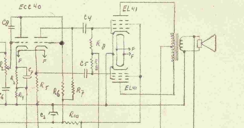
The balanced audio amplifier (Above) designed by the RBL in 1947 by Dammers, van der Knaap and Hooijmans. De ECC40 acts as single-ended-to-balanced converter, where the first triode acts mainly as a buffer, while the opposite polarity signals are taken from the anode and cathode of the second triode. The balanced amplifier as implemented in the TX1410 (Right) instead uses the two triodes in a "long-tail pair" concept, with common (grounded) cathode and thus anti-phase signals from the two anodes. The power stages are identical.
|
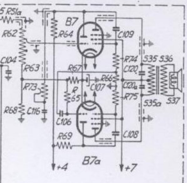
|
As said, the TX1410U platform was mainly used for export, given the very small native high end market in The Netherlands. There were consequently many derivatives adapted to local standards, regulations and conditions of the countries targeted for export. A few are worth mentioning. The first is the TX1410U-48 for the Argentinian market. Argentina used the modified 625-line standard with channel parameters similar to NTSC: a channel width of 6MHz and a picture-sound carrier distance of 4,5MHz. Although this should have been possible with a slight adaptation of the settings in a standard TX1410, the -48 version introduced a yet higher IF: 26,1MHz picture and 21,6MHz sound. The highest of any Philips sets to date. And interestingly these values were copied into the second last rear projection set of Philips; the TX1714A. This one copied the picture carrier of the TX1410U-48 of 26,1MHz, with of course now a sound carrier 5,5MHz below at 20,6MHz. Other than that the TX1714A was completely identical to its TX701A predecessor, with the exception of the balanced audio amplifier. The last projection TV was the TD2314, a Krefeld design, with a then very large projection screen of 45 x 34cm, so a diagonal of almost 23". This set went back to the 23,5 and 18MHz IF of the TX1410, and had - for cost savings? - a single ended audio amplifier, although that didn't lower the sales price below 1600DM. It was the last projection television, since picture tubes of 21 and 23" were coming soon. It marked the end of Protelgram and MW6-2 based rear projection after an almost ten year long effort to make it a success.
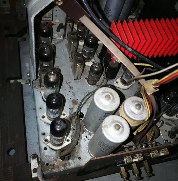
Although not formally in the Service Manual, it seems some (later?) TX1410 models like this one for Italy introduced the selenium rectifier stack, here clearly visible in red. [via Taco Vonk]
|
Surprisingly the TX1410 platform was hardly adopted by the UK Philips/Mullard organization. Until 1955 the TX400 remained the basis for all UK sets as explained earlier, albeit with steadily increasing display sizes. Only in 1955, so three years after the launch in Eindhoven and Krefeld, TX1410 derivatives were released in the UK in two versions. The first (1756, 1757 and 2157) was an almost direct copy, adapted to 405-lines and AM sound, resulting in one valve less and also introducing the 21" picture tube. A second version was intended as a cost down and featured a reduced valve count due to one video amplifier and one supply rectifier less, as well as - most surprisingly - by omitting the frame and line output power pentodes. It was therefore only available with 14" (1458 and 1468) and 17"picture tubes (1758, 1778). But whatever the basic platform, the combined volumes of the TX400-platform (in the UK and the Netherlands) and the TX/TD1400 (in Germany and other countries) jointly brought the number of television sets produced by Philips to 800.000 in 1953 and 1.250.000 in 1954. Of these numbers only 20% was produced (and sold) in the Dutch home market, meaning that Philips was really becoming a global television player.
|
Televisions for the French 819 line system, 1951
|
France remained a difficult TV market, mostly due to the complexities around the standard. The 441-line system, introduced by the Germans during the occupation, continued to be used for the test transmissions from the Paris Eiffel tower transmitter starting in 1946. It has already been explained that the country decided for the 819-line standard in November 1948. This was partly based on the result of experimental 819-line transmissions which had started in April 1948 by adding a second transmitter on the Eiffel tower. When the government formally decided for the 819 lines it was stated that the 441-line system would remain operational until 1959. This in order to prevent protests from the owners of 441-line sets.
In the years 1948-1951 the 819-line system was literally experimental, and television receivers sold in the Paris area were pre-dominantly 441-lines. This included those from Philips, which brought out the TF384A, TF390A, TF402A, TF502A, TF601A and TF704A that have been discussed already. As the names reflect, all of these were derivatives of TX platforms. The relation between the French television organization and the central Apparaten Lab in Eindhoven seems to have been much less problematic than with their Mullard counterparts in the UK. The Philips production and sales of radio and television in France was operated under La Radiotechnique S.A., a company acquired by Philips in 1931. It had its main production premises in Suresnes, immediately west of Paris along a loop of the River Seine. In France Philips marketed its products both under its own name as well as the La Radiotechnique brand "Radiola". Electrically sets were completely identical, independent of the brand name. The Radiola sets were coded RA followed by the type number, the Philips sets as TF per the Philips coding rules. |
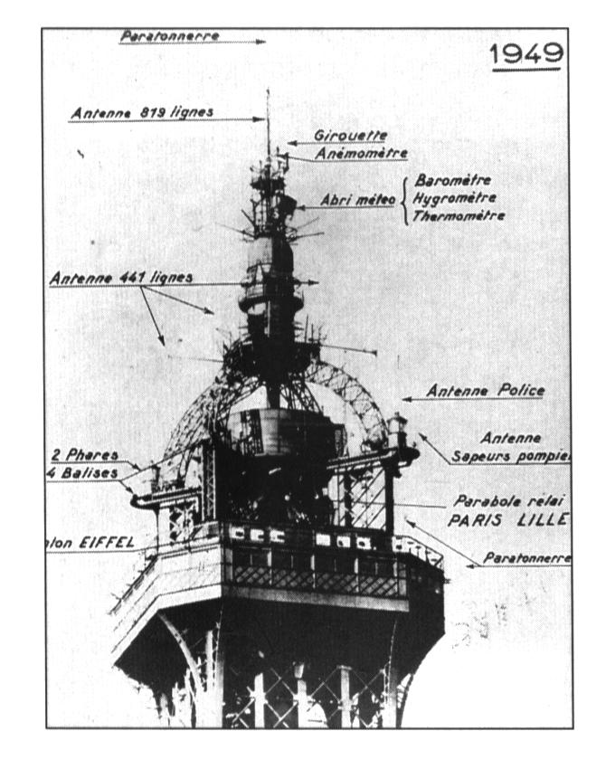
The two transmitters on top of the Eiffel Tower in Paris at an altitude of almost 300m. At the very top the 819-lines antenna and at the base the 441-line antennas. After a fire in the transmitter platform in January 1956 the 441-line transmissions were discontinued. [Forum telesatellite.com]
|
|
In May 1950 the second transmitter station in France started operations from Lille, in the north of France near the Belgian border, transmitting 819-line programs that were clearly also intended to convince the French-speaking part of Belgian to adopt this standard. At the yearly "Foir de Paris" show of 1950 the majority of sets presented was still 441 lines, although some 15% of the television manufacturers showed 819 line sets. But the next year at the first "Premier Salon de Télévision" (The First Television Show) 57 of the 81 sets shown were 819-lines. This moment can be seen as the tipping point of the new standard, because regular transmission had started May 1951. From this moment onwards we also see Philips-La Radiotechnique bring out 819-line sets.
|
Relation between Radiola and Philips Television product codes
|
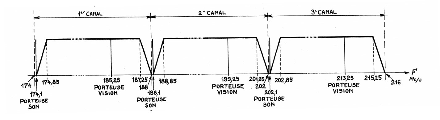
Example of the channel allocation of the VHF-III channels 8, 10 and 12 of the French 819-line standard. It shows the 14MHz channel width, the 11,25MHz sound-video carrier distance and also clearly that still 3MHz of the "upper" side band is taken into the IF for a "wide"vestigial side band filtering. This was all very good for picture quality but at the expensive of a very large bandwidth. Most interestingly, although this picture comes from the official service manual, the numbers are wrong by a few 100kHz! [TF651A Service Manual]
The first Philips 819-line set was the TF651A, which is immediately an oddity. My interpretation is that it was launched in 1951 as a speciality set for the "Premier Salon de Télévision", therefore the non-compliant product code with 51 (which would normally indicate a design from either 1945 or 1955, where neither is realistic). But whatever its origin, the set seems to have been commercially available because an official and extensive Service Manual exists. The cabinet design clearly relates it to the TX390 and 385U family from 1949-1950. Next, the set uses exclusively valves from the E40 Rimlock series, which makes it unique since all HIG Apparaten sets used U40 valves. It is highly likely that this design therefore came straight from the Radiobuizen Lab, which used exclusively E-series valves. The design seems to be derived from the TX390/29 design for the French 441-line system, but then it required a number of modifications to adapt it for the large bandwidths associated with the new standard. Amongst these:
|
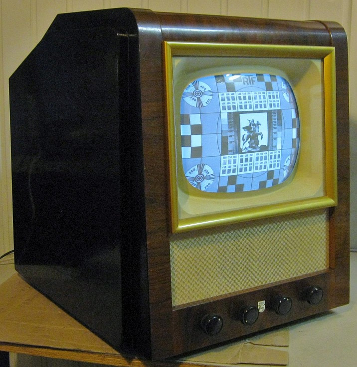
The TF651A restaured and in perfect working condition. [Jac Janssen collection]
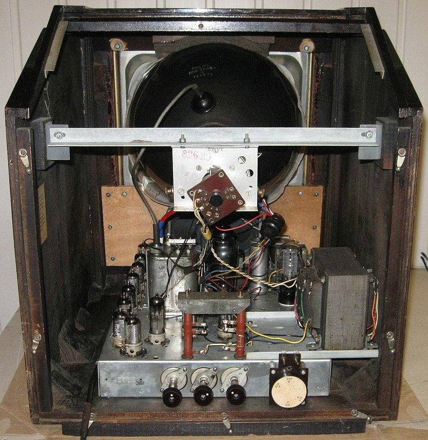
Interior view of the TF651A after restoration. Of special note is the fact that the large power supply transformer on the right has been placed on a special support plate, probably to move it as far away as possible from the deflection coils and thus avoid stray field distortion. [Jac Janssen collection]
|
Although the TF651A could in a certain way be qualified as an oddity in terms of valve use, suggesting it was a quick solution not intended for production, the opposite was the case. The set seems to have been successful, since it was quickly followed by the console version TF751A and the next year by the TF652A. The latter introduced the first Noval series valve ECL80 as well as an RF-front end based on two ECC81's. This front end seems to have been very satisfactory, since it would be used almost unchanged for the coming 4 years. The ultimate use of this "mini-platform" was the TF2323A, a rear projection version with an additional 5-valve 25kV generator block. Together with the German TD2314A from the same year this was the very last "Protelgram" rear projection set launched by Philips.
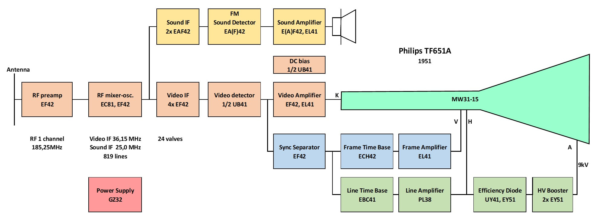
Block diagram of the Philips TF651A, the first 819-line television set of the company. It was probably a Radiobuizen Lab design pressed into (limited) production around the 1951 "Premier Salon de Télévision" in Paris.
The next French platform was more standard, and a direct derivative of the TX1410. Four models were launched in 1952, the 14" TF1426A and TF1428A, as well as the 17" TF1726A and TF1728A (with the 26-models table top and the 28-models console). However, from here France takes a different path from the central platform development in Eindhoven. So where in Eindhoven the average life time of a platform in this period is maximum two years (the TX400, TX1410, TX1720 and 17TX120 and 21TX140 cover a period of 6 years) the French development in Suresnes sticks to its basic platform for almost five years, albeit with many small modifications and extensions. But especially the deflection unit is kept constant for almost the entire period, only replacing the EL41 frame output pentode for a PL82. Although it goes too far to discuss all these features, I'll highlight the most interesting ones:
- the platform split into two parallel families, the first one a line of basic sets with 18-19 valves per TV, moderate performance and therefore only usable close to the transmitter. These sets had a last digit in the product name of 4, 5 or 6. Next to these was a line of more expensive sets with 23-25 valves, much better reception, and control loops for AGC and noise suppression. These had product codes ending with 7, 8 or 9;
- the platform, with as said unchanged deflection concept and valves, supports the screen size increases from 14" to 21", the latter using MW53-22 picture tube introduced in 1954 (TF2147, 2148, 2157 and 2158);
- it was very quick to follow the TX1720 in introducing germanium diodes for video detection;
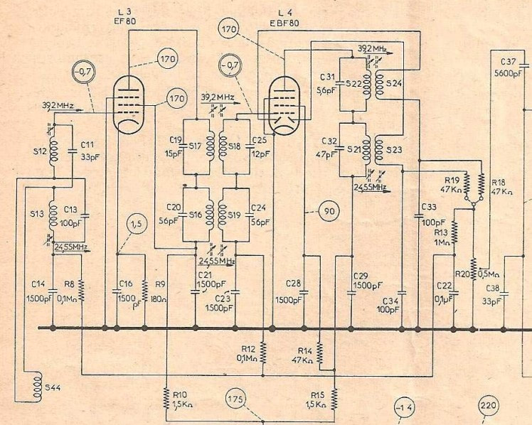
The Philips TF1446A sound IF section, showing the "dual-IF" concept. Each anode circuit contains two bandpass filters in series, the lower one tuned to the left hand sound IF (24,55MHz) and the upper one to the right hand sound IF (39,2MHz). At the detector output, far right, only one of the two IFs could be selected with R18/R19. [TF1446A Service Manual]
|
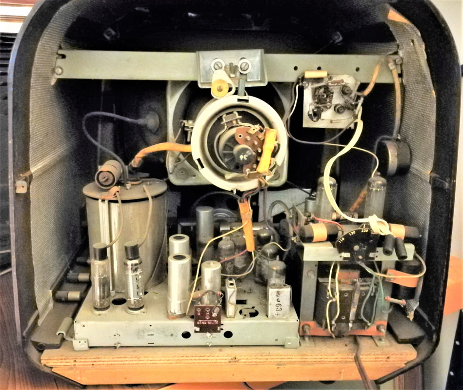
Interior view of the Philips TF1446A. On the left the cylindrical can with the HT transformer, centrally the IF and deflection frame, on the right the power supply. Note the thin bakelite encasing, not often used by Philips for TVs. [via Taco Vonk]
|
- on the tuner side the approach was very conservative. Initially the set would be tuned to a single fixed channel. In 1954 a 2-channel solution was introduced together with the PCC84 as RF-valve, but always within a single band. The tuner needed to be exchanged for either VHF-I of VHF-III reception. A single set, the TF1746B2 could receive both bands by having two tuners, an expensive solution I have, not surprisingly, not seen on any other set;
- in 1953 it introduces what I'll call "dual IF" frequencies. With the growing number of transmit channels one of the characteristics of the French standard E became an issue: the alternating frequency spectra of the channels. In order to gain back some frequency efficiency that was lost due to the very large 14MHz channel bandwidth, channels were defined in an overlapping way with inverted frequency spectrum, often referred to as "tête bêche". So channel 5 had a picture carrier of 164,00MHz and a right-handed or higher sound carrier of 175,15MHz, and similar for channels 7, 9 and 11. But channel 6 overlapped with channel 5, with a picture carrier at 173,40MHz and a left-handed or lower sound carrier at 162,25MHz, and the same for channels 8, 10 and 12. [For a more explanation see the Tuner History pt1]. Since TV sets still didn't have a tuner but were fixed to a single channel, the IF could be either right-handed or left-handed. The solution to this was that all IF circuits were doubly tuned, with a picture IF that could be 28,05MHz in combination with a 39,2MHz sound IF (for even numbered channels assuming an LO above the RF channel) or 35,7MHz video IF in combination with a 24,55 sound IF (for odd-numbered channels);
- only very late the 12-channel drum tuner was introduced, in 1955. This made it now possible to put the RF local oscillator either above or below the RF channel to obtain a uniform IF allocation. The dual-IF concept was thus dropped, but surprisingly the right-hand allocation was kept, i.e. picture at 28,05MHz and sound at 35,7MHz.
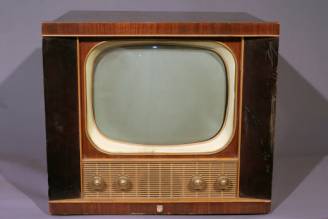
Philips TF1726A from 1952. [All these eight pictures from Antique-TV-Blazianu]
|
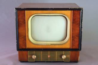
Philips TF1435A (1953).
|
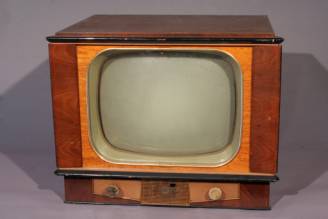
Radiola RA4335A, equivalent to the Philips TF1735A (1953).
|
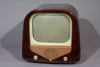
Philips TF1436A (1953)
|
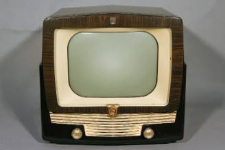
Radiola RA4336A, equivalent to the Philips TF1736A.
|
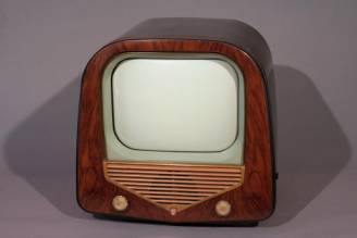
Philips TF1446A (1954).
|
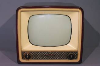
Radiola RA4366A, equivalent to the Philips TF1766A from 1956.
|
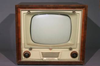
Philip TF1767 (1956) the last from this platform.
|
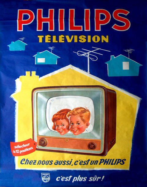
French advertisement of the TF1761 TV set from 1956. [Philips Reclamekunst]
|
In 1956 the last of this extended family was launched, the TF2167A/RA4367A, five years after the first TF1426A, making it the longest living family of this decade. Next platforms were again based on the concepts coming out of Eindhoven and will be covered in the chapters on these new families. A last interesting observation is that the Philips/La Radiotechnique organization in France apparently did not adopt the new product coding scheme of 1953, and the TF-name thus lived on till the end of the 1950's, whereas in most other countries the new scheme starting with the screen size was introduced.
|
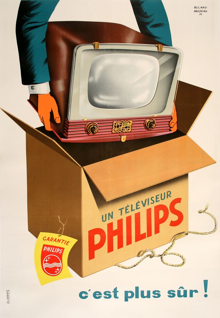
Another advertisement of what looks like the same TF1761.
|
The last development that needs mentioning is the production facility. As discussed earlier, around 1953 the Philips management finally took the decision for serious expansion of its television-related production capacity. This was driven by the steady growth and the apparent success of the new television market, and secondly by the need to manufacture its own picture tubes due to the lack of viable alternatives. First expansion took place in the Netherlands (Eindhoven), Germany (Krefeld) and UK (Mitcham), but in the course of 1953 also France television sales picked up with the 819-line standard now really becoming operational. The platforms mentioned above were still produced in the La Radiotechnique Suresnes (Paris) factory, which quickly became too small. When Philips looked for locations west of Paris for new factories the maire of Dreux was quick to respond, offering cheap land, abundant labour and (to be upgraded) infrastructure. In this he was successful, and construction started of both a picture tube factory as well as a television factory in this city, some 50km due west of Paris. Construction started in 1956 and the first sections were opened in 1957, quickly becoming a major production plant that operated around the clock. Some of the models mentioned above will have been the first ones produced in this factory starting 1957.
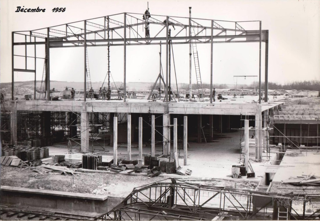
The Philips Dreux television factory under construction, December 1956.
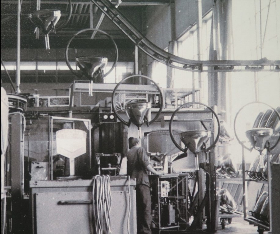
Transport chain of finished picture tubes leaving the factory to their intermediate storage, 2,5km away on the same complex.
|
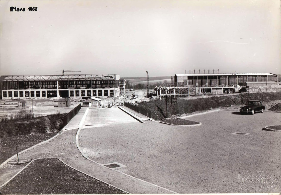
The Dreux factory nearing completion, March 1957.
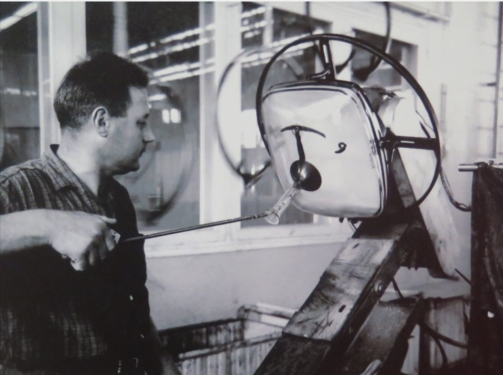
Quality control of a picture tube during production. All six pictures from http://dreux-par-pierlouim.over-blog.com
|
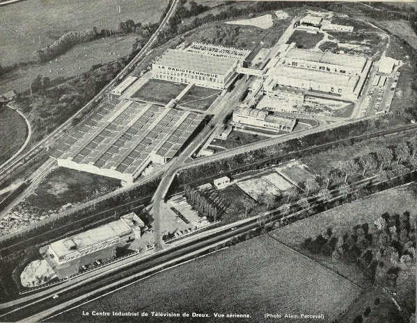
The Dreux complex after completion, probably early 1960's. On the right the picture tube factory, on the left the TV factory. Note the name on the building is "La Radiotechnique", not Philips!
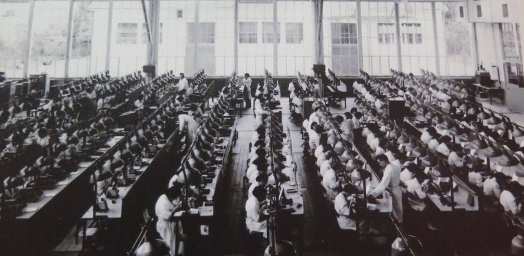
Interior view of the Philips Dreux production facilities. This is most likely the electron gun assembly for the picture tubes.
|
New concepts, new valves
In parallel to the TX400 and TX1410 platform developments in the Apparaten Lab, innovation had not stopped. It is never entirely clear which developments took place in the Apparaten organization pre-development group - if that existed, which I assume - or in the Radiobuizen Lab. Again we only have a view on the RBL activities through their Electronic Application Bulletin publications. At the same time we will see a high transfer rate of RBL ideas and concepts (as published in the EAB) and their application in actual television products. Given the reputedly good co-operation between the two labs I simply assume most innovations are the result of the interaction between the two groups.
The two innovations most relevant for the next generation TV's are inter-carrier sound and the tuner, both also linked to the introduction of new valves.
The two innovations most relevant for the next generation TV's are inter-carrier sound and the tuner, both also linked to the introduction of new valves.
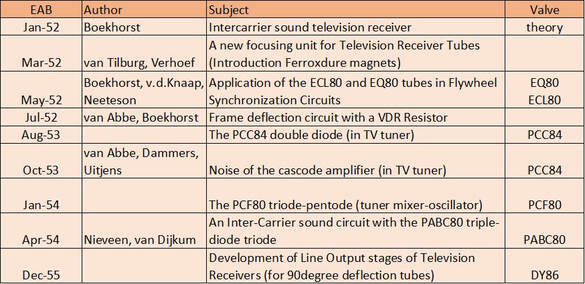
Articles published in the Electronic Application Bulletin of the HIG Elektronenbuizen from 1952 to 1955.
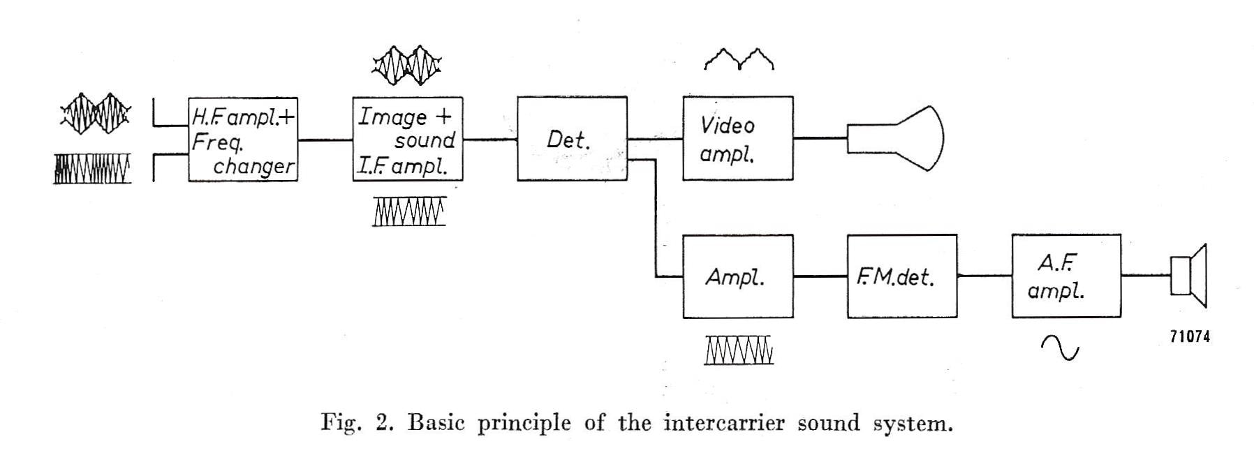
So far all televisions had used dual IF branches for video and sound. In most platforms the audio branched-off after the first EF42/EF80 IF amplifier, where-after the video IF chain continued with another 3-4 IF stages, while the audio branch usually required another two IF amplifiers. In these two stages further bandpass filtering takes place, with higher selectivity due to the lower audio bandwidth, while the amplitude is increased to the minimum 9V required to drive the EQ80 FM detector. Overall this resulted in about 7 IF amplifier stages that all required careful (staggered tuning) alignment for optimum transfer characteristics.
In an inter-carrier receiver the video and sound remain combined throughout the entire IF chain up to and including the video detector. The output of that detector will now be the video baseband signal as usual but with the modulated sound on a sub-carrier at 5,5MHz, the picture-sound distance in the Gerber-norm. (In other standards the video-sound distance differs of course). The advantage is then that the remaining audio chain is much more low frequency up to the FM detector, avoiding more complex IF circuitry. The down side is that the combined video plus audio IF chain needs to be more wideband to pass both signals. Probably as a consequence of this the IF frequencies further moved upwards to a picture carrier of 38,9MHz and a sound carrier of 34,4MHz.
The first EAB article by Boekhorst in January 1952 still based the FM detector on the EQ80. However, despite its consistent use in all FM-sound receivers so far, the use of the EQ80 was coming to an end. The replacement valve was the EABC80/PABC80/UABC80, a diode plus dual diode plus triode, a typical example of valve optimization by the Radiobuizenlab. The dual diode and the triode shared a single cathode, but the single diode had its own cathode. In combined AM/FM radio receivers this valve would be widely used, with the first diode (A) the floating FM detector diode, one of dual-diodes (B) the lower FM detector, and the triode (C) as audio baseband pre-amplifier. The second diode of the dual-diode (B) was used as AM peak detector in radio receivers, while in TV sound chains it was mostly used as AGC peak detector. The first PABC80 in a TV receiver was reported in April 1954, and would indeed become the solution in the next TX1720 platform. Note that the PABC80 was mostly used as an FM ratio detector, with the two FM detector diodes anti-parallel.
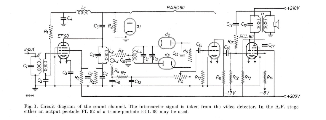
|
The second critical innovation area was the tuner. Since the tuner is the first circuit where the often weak received signal enters the television, it is critical for the overall set performance. Any signal-to-noise degradation incurred at the tuner can not be corrected afterwards. The first tuners as used in the TX380 and TX390 were marginal at best. They suffered from bad noise performance and drifting oscillators. A first but modest improvement was the introduction of the EF80-based tuner in the TX400, although the self-oscillating mixer was not a very strong concept. With the TX1410 that problem was solved with the introduction of the ECC81 as second valve, which separated the oscillator and mixed. But the EF80 as input stage remained weak, simply because of its modest RF performance.
The Radiobuizen Lab drove the development of two new valves, dedicated for television tuners, almost certainly pushed by the Apparaten Lab. The first was the PCC84 RF double-triode to be used in the input stage of the tuner in a so-called cascode configuration. In such a circuit the first triode anode output is connected to the cathode of the second triode, which is used in a grounded-grid configuration. Dammers and Uitjens of the RBL were clearly involved in this activity, and wrote the theoretical analysis of the tuner noise of a PCC84 cascode amplifier. |
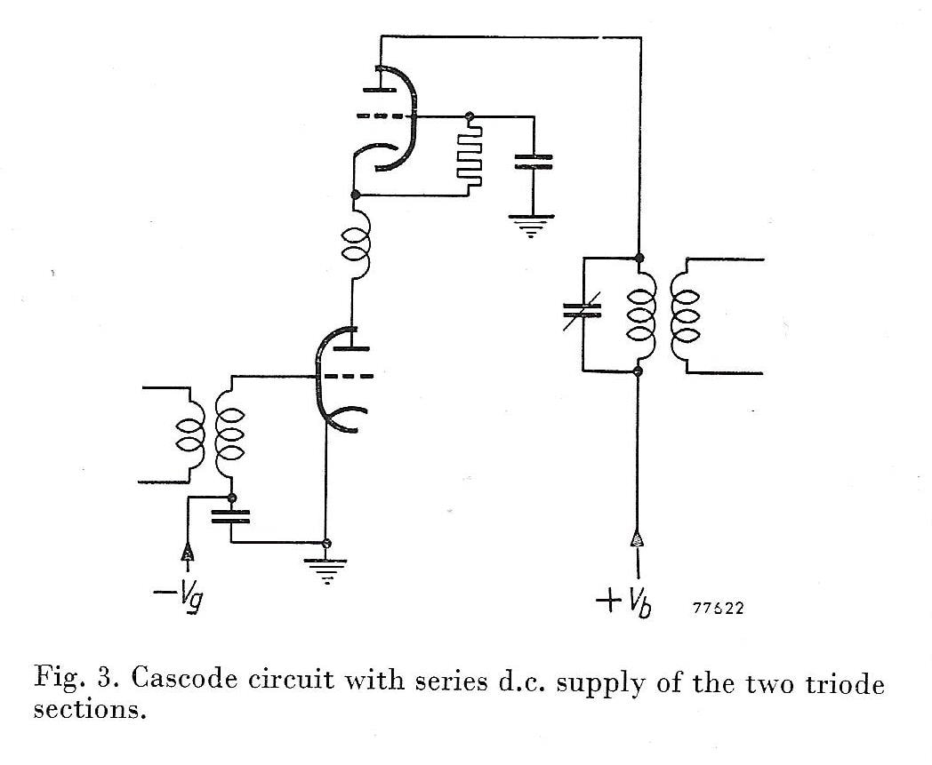
The principle of the cascode low noise wideband amplifier. Because the first triode load is the low input impedance of the second cathode its gain is close to 1, which means that the Miller feedback capacitance at its input ( (1+Gain)*Cag ) is low, facilitating a high bandwidth. To avoid parasitic feedback due to stray capacitances between the triode sections, they were separated by a screen that could be grounded. [EAB August 1953]
|
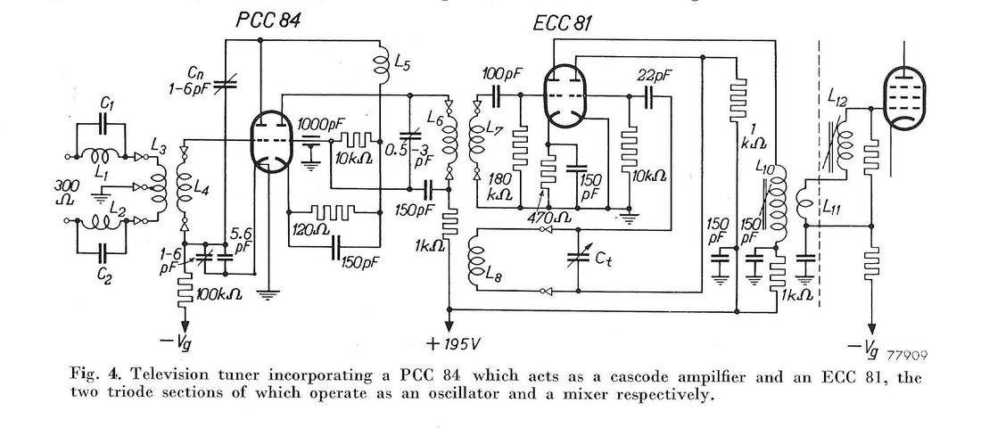
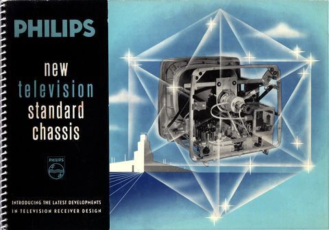
Advertisement for the new Philips TV standard chassis, around 1952-1954. [Philips reclamekunst]
|
The second step was the introduction of the PCF80 RF triode-pentode as replacement of the ECC81. The main drawback of the dual triode was its low isolation between anode and grid, which is much better in a pentode. As in the PCC84 the two sections in the PCF80 were separated by a screen. Furthermore the cathode and grid construction of the pentode were oval, giving a constant cathode-to-grid distance around the circumference, and thus better frequency-independent gain up to higher frequencies.
In actual television platforms the PCC84-ECC81 solution was skipped (although it should be mentioned that the French TF1410 platform used the ECC81-ECC81 concept for many years) and with the TX1422 the PCC84-PCF80 tuner AT7530 was introduced. These valves would stay the default solution for the tuner for a number of years until replaced by the PCC88. |
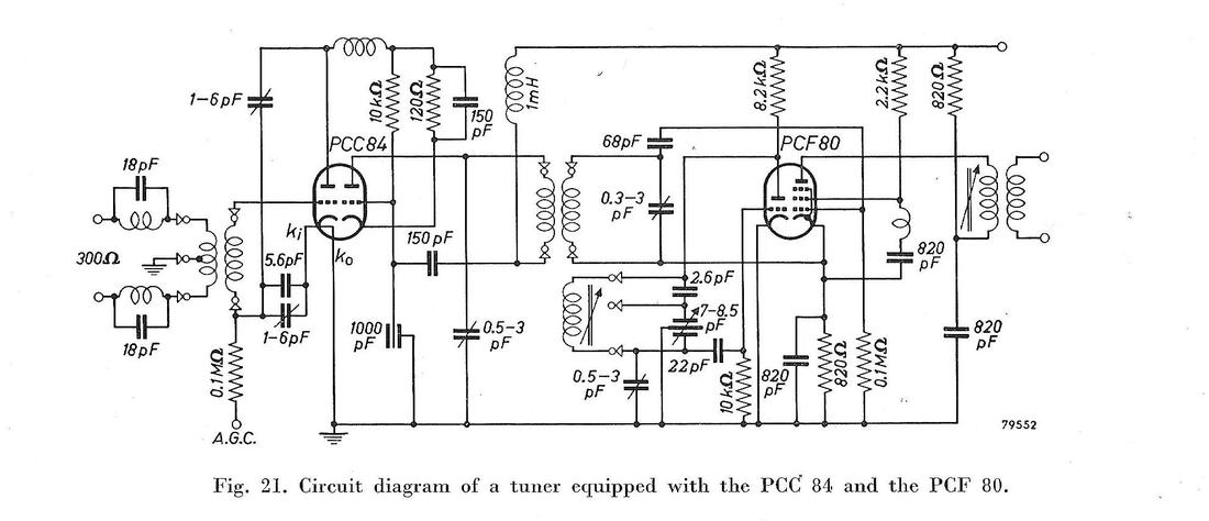
|
A last continuing innovation was the picture tube size, which steadily increased from 14" to 17" (1954) and by 1956 to 21". In order to avoid that the picture tubes became too "deep" (orthogonal to the screen) it was necessary to use ever larger deflection angles for the electron beam. For the 21" screens this approached 90degrees! This in turn required that the deflection magnetic fields generated more electrical energy, which ultimately required larger voltages. For the 21" tubes the required anode voltage of the tubes had increased to 18kV. This was at the limit of what the venerable EY51 could withstand, and therefore the DY86 was introduced as its replacement, quickly followed by the almost identical DY87.
|
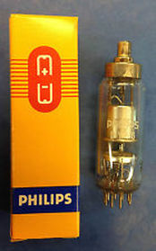
The DY86
|
Semiconductors
So far the history of television development has been entirely radio (and picture) valves centric. And it would stay so for another decade. In the background, however, an entirely new development was taking shape: semiconductors. Especially the concept of semiconductor diodes was not entirely new. During the war both in Germany and the US some diodes were developed as detector in radar systems, but they remained exotic. In 1946 the US war effort on these type of materials was published and available to its allies in a 28-volume overview. At Philips Research this triggered one group under dr. Piet Haaijman, in the sector of Herre Rinia, to have a few researchers working on metal-based detectors, using such materials as selenium and germanium. (As we've seen in the previous chapter, the SG860A and SX861A TV sets from 1946/47 contained two selenium detectors, although almost certainly no Philips components). These activities came into a completely new perspective when in 1947 the the transistor was invented by John Bardeen, Walter Brattain and William Shockley of Bell Labs. This sent a shock through the world of electronics, and also within Philips kicked off semiconductor research. In 1948 Evert Verweij, one of the three NatLab directors, toured the US and concluded that research should be focused on germanium as base material. The group of Haaijman was extended to accelerate the work on germanium diodes, whereas a second group under F. Stieltjes started work on the transistor. One of the young researchers in this group was J. Tummers, who, as a graduate student from Delft, was initially the only engineer working on transistors in Research. He would be the leading developer of transistors within Research the Research group of Haaiman. Especially the transistor was a hard nut to crack, and progress was slow, also because Bell Labs had disclosed only a minimum of details on the engineering of their transistor, while also the US Department of Defence pushed hard to keep it top secret. It was only by 1952, with the famous Bell Licensees Symposium, that Bell Labs shared the "Transistor Cook Book" with a selected set of companies with which it has cross-license agreements. From Europe this included Philips, Siemens, AEG-Telefunken and GEC. So far the NatLab had worked on the point-contact transistor, but these were very sensitive and unreliable, and after the Bell Symposium they switched to grown junction transistors.
|
Quite quickly after the announcement of the transistor invention, it became clear to the Philips management that this was an important development that the company could not ignore. By 1949 the research activities of the group of Piet Haaijman resulted in what was thought to be a producible germanium diode. At this point the HIG Elektronenbuizen decided it would create a dedicated Industriegroep Halfgeleiders (Industrial Group Semiconductors) within their HIG. On the one hand this was to give it the proper attention and focus, on the other hand it was to protect the radio valve group from distraction, giving its massive effort to role out the new families of television valves. At this time Jan van Vessem had succeeded Gerrit Alma as head of the Radiobuizen Labs, while ir H. Hazeu was the technical director of the HIG after Theo Tromp moved to the Philips board of directors in 1946. Hazeu and Tromp got along very well, and jointly pushed innovation, the importance of radio valves and picture tubes, but also recognized the importance and opportunities of semiconductors. Leader of the semiconductor activities became dr. Jan van der Spek. A production facility was built in Eindhoven and in 1950 the first products were delivered; the OA70 and OA50 diodes. The OA70 used germanium with a higher conductivity and consequently had a high bandwidth, making it fit for video detection. The OA50 was made or "regular" germanium and was a low frequency detector, so suitable for audio or synchronization signal detection. Because production was still unstable, the output was "binned" with lesser products sold as OA51, OA52 and OA56. By 1952 they were succeeded by the OA60 and OA61. Almost as soon as they appeared the germanium diodes were used by the Apparaten Lab for the functions as described. They were first used in the TX1422 platform released in 1952, and thus in commercial sets from 1953.
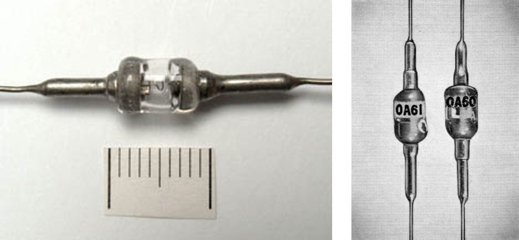
Left the OA50, right the OA61 and 60. [Philips Historcal Products]
|
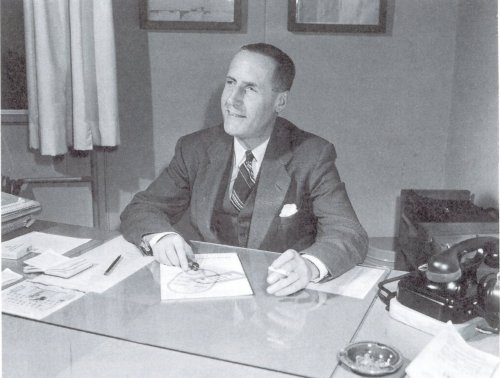
Ir. Hazeu, head of the Radiobuizen Labs from 1949. [Dos4ever]
Dr. Jan van der Spek, director of the Nijmegen semiconductor factory, here seen while offering Fieldmarshall Bernard Montgomery a transistor radio during his visit to the fab in 1956. [Market Garden Veterans]
|
As soon as the first generation diodes came available the company struggled with production capacity. The small-scale Eindhoven production facility was soon too small, and a second site was opened in Heerlen, but even that was not sufficient to cope with the demand. By the end of 1952 the pressure increased when, after the Bell Symposium, better transistors were in development. In a policy meeting where neither Tromp nor Hazeu were present, especially the NatLab representative Herre Rinia proposed a massive switch from radio valves to semiconductors, with 50% of the HIG Elektronenbuizen R&D budget to be allocated to semiconductors. When he heard this Hazeu was shocked, and together with Tromp was able to reverse the decision. But it was decided that the HIG would put more resources into semiconductor development. Production of the point contact transistors OC50 and OC51 was problematic, having a yield of only 30% and a production output of barely 250 pieces per week. Furthermore the Philips board gave the green light for the construction of a brand new large semiconductor factory in Nijmegen, construction of which was started immediately. It was also decided that all semiconductor developments were to be concentrated in Nijmegen too. The nucleus around which this factory was created was formed by the transistor development group of the HIG Elektronenbuizen of ir. Jan van der Spek. He also became the first plant manager of Nijmegen. The factory opened end 1953, january 1954 test production of the new transistors OC70 and OC71 started, and March 1954 volume production ramped up. By 1955 this plant had grown to 1100 employees, of which 122 in development.
|
Transistor developments in the meantime proved more problematic. The NatLab had, after initial work on point contact transistors, switched to the so-called growth or double-doping transistors, based on the information obtained after the Bell Symposium. By the end of 1952 they had made 100 transistors and proposed these be taken into production by the IG Halfgeleiders. The director of the Radiobuizen Lab Jan van Vessem and his staff were, however, not convinced of the reproducibility of this technology. Van Vessem was convinced that the RCA technology of alloy junction transistors was much better and he proposed licensing that technology. Due to rather blunt behaviour by Philips in the negotiations it took almost a year to obtain the desired license from RCA. Although a first three transistors were announced already in 1953, the OC10 to OC12, these were hardly producible, showing a yield of just 10%, and effectively never came beyond the sample status. The first successful production transistors out of Nijmegen were the OC70 and OC71. Both were germanium PNP transistors in a glass encapsulation, suitable for audio and other low frequency applications, and launched in 1954. However, where the germanium diodes were adopted very quickly, it would take much longer for transistors to appear in the Philips television and we won't see them in the next platforms.
|
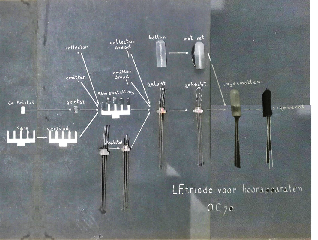
A unique contemporary board with hand-written explanation (in Dutch) of OC70 transistor fabrication process. On the centreline is from left the germanium crystal (Ge kristal) which is subsequently etched (geëtst). Five of these crystals are mounted on a comb (kam) which is then tinned (vertind). Emitter and collector dopes are added and on the picture visible to the naked eye! This results in an assembly (samenstelling) of five processed transistors. Each transistor is then separated and mounted on the wire set fixed to the glass foot (plaatstel) and being welded (gelast). The emitter and collector wires were then added to connect to the other two pins (gehecht). To finish the glass cover (ballon) is filled with wax (met vet), mounted and molted (ingesmolten). As a last step the transistor received a black paint cover to make it insensitive to light (afgewerkt). Title of the entire board is "AF triode for hearing aids, OC70". [It probably comes from the Philips Research NatLab historical collection and has been displayed in the NatLab cinema in Eindhoven that uses the first NatLab building.]
|
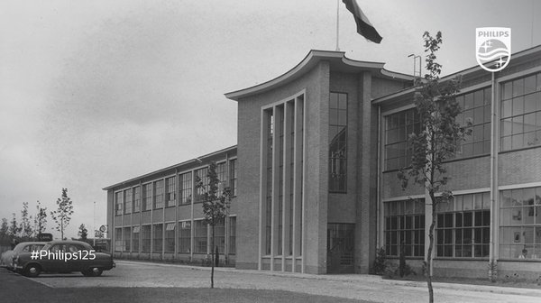
The new building of the Philips Halfgeleiderfabriek at the Gersteweg in Nijmegen, 1953. [Philips]
|
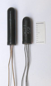
The OC70, the first Philips transistor, 1954. [Philips Historical Products]
|
Maturity, 1953-56
|
By 1953 television development and production came into the next phase of maturity and growth. With the launch of TV transmissions in Germany (December 1952), Belgium (October 1953), Switzerland (1953), Italy (January 1954) and Denmark (1954, after local test transmissions since 1951) all of Western Europe now had television services, and the market was thus rapidly expanding. This also had its consequences for the HIG Apparaten, which was unable to serve all countries from its single Eindhoven Apparaten Lab and Apparatenfabriek (the factory). Starting from 1953 television development was rapidly localized, which meant that set development for a country took place at the local production plant. These were at the time:
|
With the rapidly growing market there was the need for more advertising. In 1951 Philips had this poster designed by the French artist Adolphe Mourin titled "Cassandre".
|
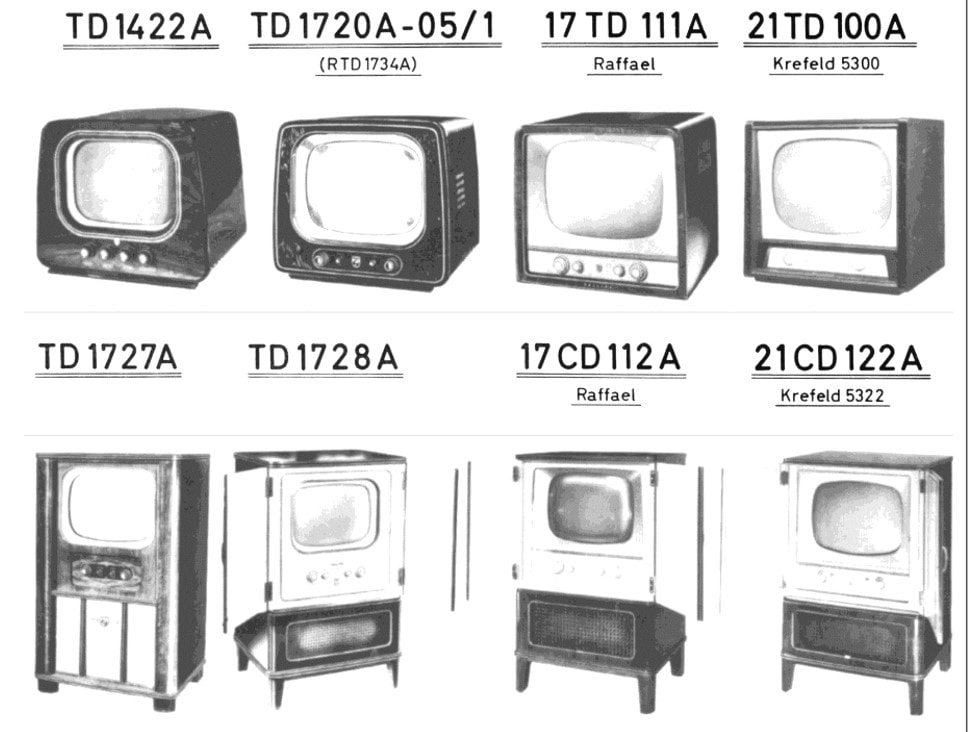
Example of the different models derived from a single electrical platform, in this case the TD1422. The family contains three different screen sizes (14, 17 and 21"), basic models (21TD100A) and high end models (TD1727/28) and table top (TD) as well as cabinet (CD) models. The naming also shows the change of model coding as implemented mid 1953. [Philips Service Manual]
|
Another trend was rapid diversification. Although the primary parameter for differentiation between low end and high end TV was the screen size, the cabinet design and size also still played an important role. After all the TV was an expensive device that took a central place in the living room, and the size of the cabinet reflected the price. Although in Europe the console - as it was called - or large cabinet never became as popular as in the US - where in the nineties still many of these large ugly sets were sold - they were still an important selling element in the early fifties. Within the context of this story all these derivative models are not very relevant, so in these last sections I will only look at family level, defined by a common electrical platform. For the period 1953-1956 these were:
|
|
1. TX1720, 1952
Before we go to the real TX1422 first product of this platform we briefly need to have a look at an oddity; the first TD1422. At the end of the (design) life time of the previous TX1410 platform a last model was designed with two versions, the TD1420U and TD1422U. The timing and coding suggests these may have been one of the very first products produced in the brand new Krefeld factory, but still designed by the Apparaten Lab, since for 95% identical to the TX1410 platform. The later timing is proven by the fact that these were the very first sets using semiconductors! In both the video detector and the two line phase detectors the EB41's were replaced by an OA60 and two OA51's, respectively. However, for unknown reasons the TD1420/22 was only short-lived and succeeded by a product with the same name based on the new TX1720 platform. But the first TD1422 has its modest place in history due to two milestones: it was the first Philips TV using semiconductors, while simultaneously it was the last TV using the beautiful EQ80 enneode. From now on the FM detector role would be taken over by the PABC80, soon to be replaced itself by germanium diodes. |
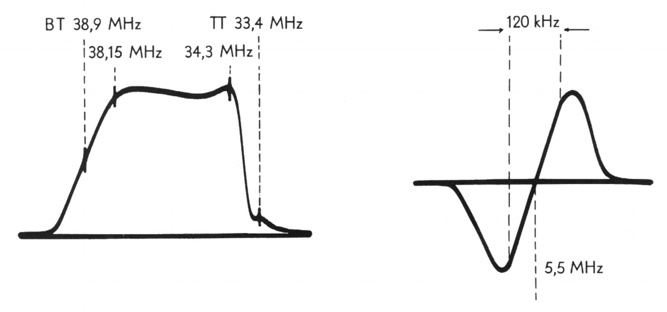
Starting with the TD1720 platform the IF frequencies moved to their "final" values: picture carrier 38,9MHz, sound carrier (for CCIR-B) 34,4MHz, intercarrier sound at 5,5MHz. Left is the IF bandwidth scan, right the FM demodulator characteristic. [Philips Service Manual]
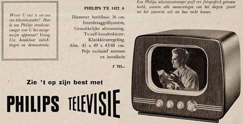
Advertisement for the TX1422A
|

The Philips TX1720, designed 1952, released 1953. This was the first platform using intercarrier sound as well as the 17" MW43 picture tube. It also introduced the PCC84-PCF80 improved 12-channel tuner, germanium semiconductors as well as the option to receive FM-radio.
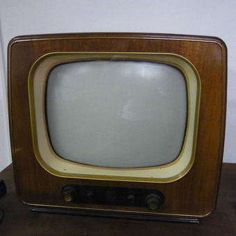
The TD1720A. [eBay]
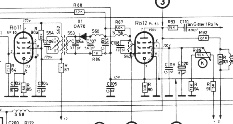
The video detector of the TD1422A using the OA70 germanium diode. Immediately after the detector the 5,5MHz sound carrier is tapped-off towards the sound chain.
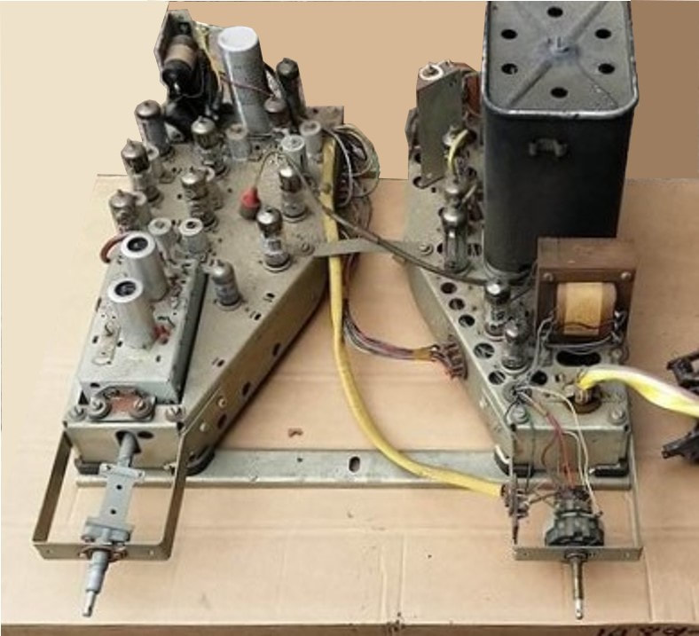
The chassis of the Philips 1756 405-line UK set, derived from the TX1720 platform. Note the tuner inserted into the left chassis section. [UK Vintage Radio and Television Forum]
|
The "real" TD1422 (officially with suffix C1) was part of the TX1720 platform. [At this time there was no formal Philips naming for platforms - as far as I know - so I use the name of the first, basic and most characteristic model to identify platforms. In this case I use the TD1720 because 17" was the most used screen size in this family, compared to the 14"of its TX1410 predecessor]. Although the platform still seems an Eindhoven Apparaten Lab design, the bulk of the products was produced in Krefeld and received TD product codes. Products from Eindhoven were mostly for export, e.g. the TX1721A/61, a model for Argentina adapted to standard N (6MHz channel width).
The TX1720 platform introduced a number of innovations. To start it pushed the IF to what would become its final value: 38,9MHz picture carrier, 34,4MHz sound carrier. It also introduced intercarrier sound, reducing the number of IF tuned circuits and the associated alignment, and continued the use of germanium diodes for peak detectors. The first generation diodes had already been replaced, so the TX1720 used the OA70 (video detector) and OA71 (line phase detector). Next it introduced a dedicated EF80 for a more advanced Automatic Gain Control (AGC), while the FM-detector was as already mentioned no longer the EQ80 but the PABC80. The deflection circuits were almost identical to the previous TX1410 platform, but this platform introduced the new 17" MW43-43 picture tube. For the first time this meant that TV sets were not a large box with a small screen, but that the screen started to dominate the cabinet size. They slowly started to look like TV's as we know them from our youth. The last and not unimportant innovation was the introduction of the new tuner using the PCC84 cascode pre-amplifier and the PCF80 mixer-oscillator. Also in the domain of set assembly innovations took place. The sets produced in Krefeld thus consisted of two large modules: the small-signal frame, containing the IF, video and sound chains. The tuner was mounted as a separate module on the side of this frame. The second frame carried all deflection and high-voltage circuitry, as well as the power supply. With this approach the two frames could be assembled and tested separately before being joined in final assembly. All in all a major step forward. In Krefeld alone already eight sub-models of the platform were produced (see the picture above), and at least the same number from Eindhoven. And finally, at the end of its life time, the platform saw the introduction of the first 21" AW53-20 picture tubes in 1954. The UK versions of the TX1720, adapted to 405 lines and AM sound, were the 1756 and 1757, while the 2157 also introduced the AW53-20. Like the Krefeld chassis also these sets were built up from two chassis sections: one small signal and one deflection. But whereas the German designers made two rectangular modules, the Mitcham designers came to two wedge shaped modules, allowing for the picture tube to be placed in between. |
The 1953 Philips Television product coding scheme
By 1953 yet another product coding scheme change was implemented like 17TX120A. From now on it was:
The first generation was simply called "Krefeld" followed by four numbers. The first two indicating the screen size in centimetres (not inches!), the last two identical to the last two of the formal product code. The first one was the the 21TD100A, which was marketed as the Krefeld5300.
The next year the "Raffael" was introduced - without the numbering - which seems to have been the more low end models within the platform. At the same time the Krefeld-series was replaced by "Leonardo", which were the high-end models within the range. Especially Leonardo would live till the end of the fifties. As far as I can see this naming of the products was typical for Germany and not copied in other countries.
By 1953 yet another product coding scheme change was implemented like 17TX120A. From now on it was:
- First two digits: screen size in inches (14-17-21)
- First letter: T=Television, C=Console, R=Radio-TV combo
- Second letter: Producing country; unchanged from previous standard
- Third digit: Generation.
This seems to be a fairly undefined characteristic, but generations seem to have lived some 5 years - Fourth digit: Platform or family within a generation, in principle still the last digit of the year of development release.
But this doesn't seem to be consistently applied, so sometimes it is used more liberally to indicate the order of platforms. - Fifth digit: individual product identifier and luxury level indicator, where higher is more luxurious.
The first generation was simply called "Krefeld" followed by four numbers. The first two indicating the screen size in centimetres (not inches!), the last two identical to the last two of the formal product code. The first one was the the 21TD100A, which was marketed as the Krefeld5300.
The next year the "Raffael" was introduced - without the numbering - which seems to have been the more low end models within the platform. At the same time the Krefeld-series was replaced by "Leonardo", which were the high-end models within the range. Especially Leonardo would live till the end of the fifties. As far as I can see this naming of the products was typical for Germany and not copied in other countries.
|
2. 17TD120, 1954
After the success of the TD1720 platform, which seems to have run in serious numbers, there was the growing need for more differentiation. On the TD1720 platform both the expensive 21CD122A and the basic model TD1422A were based on exactly the same electrical chassis. This was a non-optimal situation; the low cost models were relatively too expensive, the high end models didn't have sufficient features. The next platforms were thus split into two, with the 17TD120 being the low cost family. To this end a platform with - for Philips up to then - the lowest number of valves ever was designed; only sixteen! This was done by squeezing out every function and making maximum use of the latest semiconductors and combination valves, including the new PCF80. It used a minimum of only two EF80 IF amplifiers plus the pentode part of a PCF80 as video output. (For comparison the TX1410 used five IF amplifiers, the TX1710 four!). Also the FM detector was now replaced by germanium diodes (three OA71's), while the sync separator plus line time base chain was only two valves (one PCF80, one PL81). It must have made the performance marginal, probably only good enough for what was then called a "regional receiver" i.e. close to a transmit tower. Nevertheless at least five TD-derivatives in the "Krefeld" range were produced, as well as some Dutch TX-versions. One of these, the 17TX123A saw the introduction of the DY86, replacing the EY51 high voltage rectifier after almost ten years of good service. As a result of the low valve count the chassis was very small, roughly half the size of its predecessor, further contributing to the cost reduction. At the same time the low cost of the basic TV chassis made it possible to make relatively cheap combo's. A good example is the 17RD122A, where in the empty space below the picture tube a complete six-valve Philetta254 three-band AM plus FM radio chassis is mounted. |
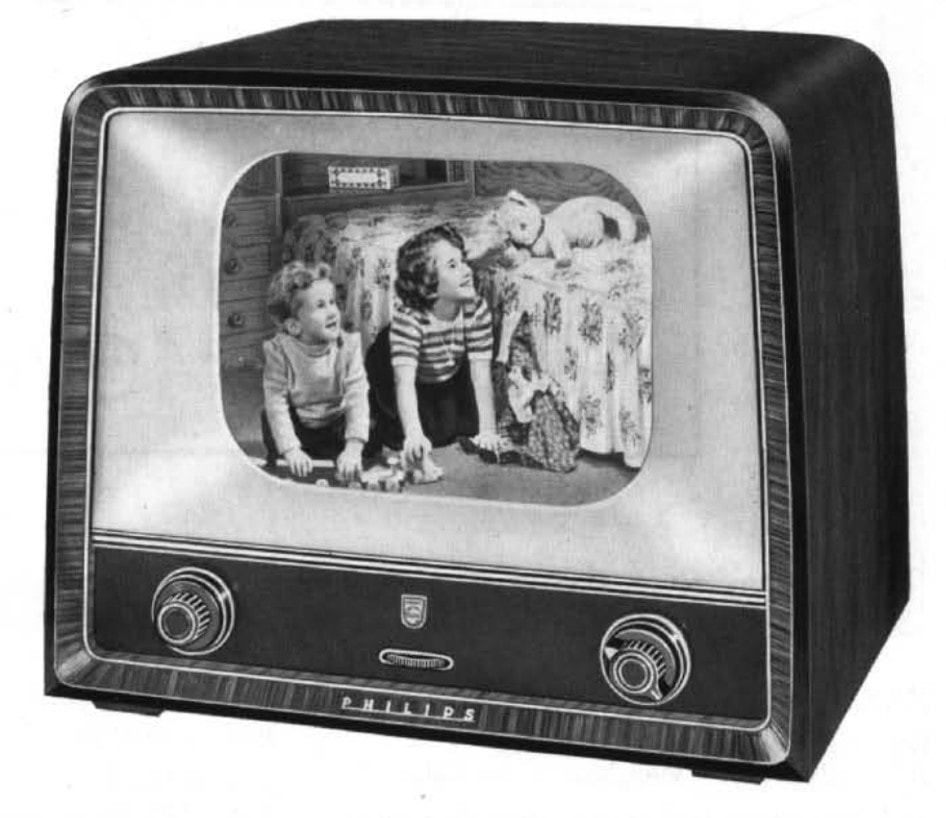
The 14TD120A, the smallest screen size version of the 17TD120 family, 1954. [Philips commercial leaflet]
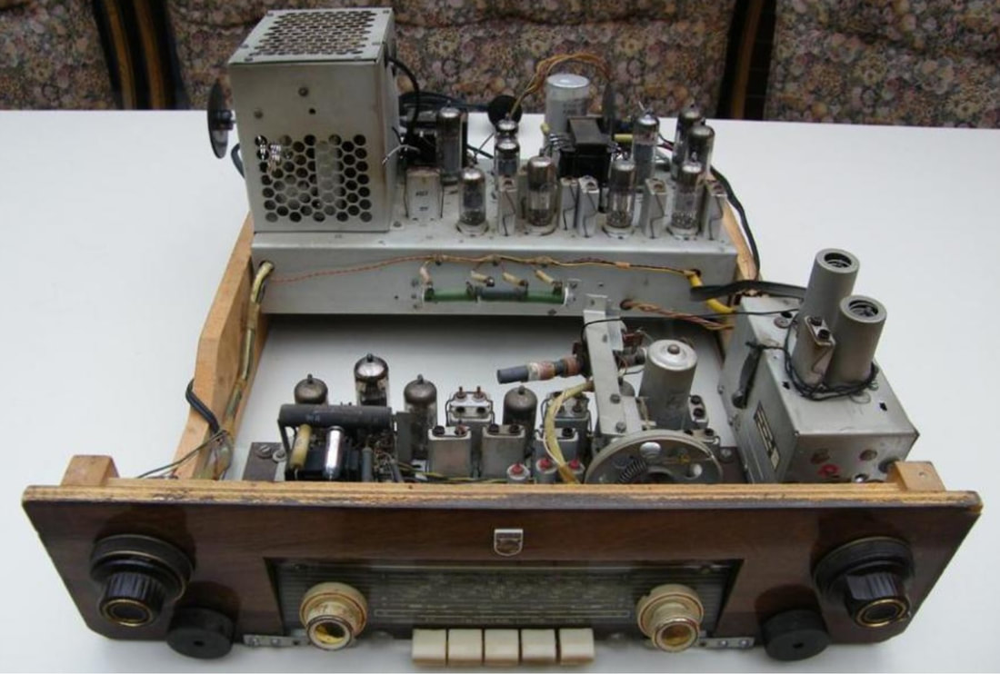
The interior chassis of the 17RD122A. In the back the very compact television chassis from the 17TD120 platform, on the right the tuner with the PCC84 and PCF80 on top, and in the front the complete radio chassis.
|
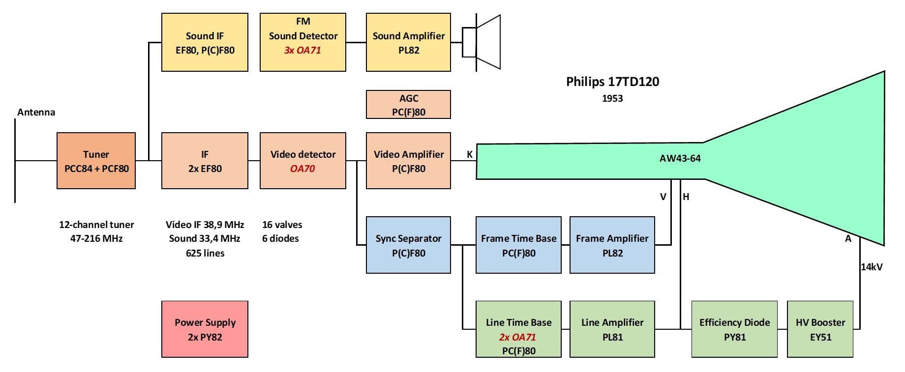
Block diagram of the Philips 17TD120 platform from 1953. This was a low-end platform, using only 16 valves, partly made possible by 6 germanium diodes. It still used the old sound concept, not intercarrier.
The UK low end platform was not a direct modification of the 17TD120, but a mix of a 1756/1757-derivative and the 17TD120 approach with an interesting different way of optimizing. In the 17TD120 as shown above, the two time base oscillators used the triode sections of the PCF80 video amplifier and synchronization separator, each followed by a PL81/PL82 power pentode end stage. The 1757/1758 platform, in contrast, used an ECL80 for each of the the frame and line time bases, an EB91 as synch separator and an extra EF80 plus PL81 for the video stage. Including one PY82 less they came to exactly the same valve count: 16. It shows that, based on the local valve preferences, using different valve functional partitionings could lead to the same result.
TV transmitter coverage extension, 1955-1958
Although all Philips TVs were equipped with 12-channel turret tuners from 1953 onwards, reality was that most people able to receive only one single TV station. At best, because large areas were not covered by any TV transmitter. With the three channels in VHF-I (channels 2 to 4, channel 1 was effectively never used except in the UK) it was also difficult to provide national coverage because transmissions on the same channel from different transmitters were not allowed to overlap in order to avoid interference. Full national coverage thus had to wait for the eight VHF-III channels. The VHF-III channels had been standardized during the early 1950s and were thus made available on the 10- and 12-channel tuners, but actual transmissions were still missing. Roll-out of VHF-III effectively only started around 1954, but depended per country whether the majority of the TV sets had migrated to the high-IF. Germany and Belgium were thus early adopters, while France and the UK, with much more legacy systems, only started around 1956-57. The Netherlands started in 1955. The process was more or less identical in all countries, with a primary network of high power VHF-I transmitters for initial maximum coverage, and then smaller medium-power VHF-III transmitters filling the gaps. However, as part of its Service Documentation updates that were sent to TV sellers and repair shops, Philips also regularly provided updates of the transmitter coverage across the country. That gives an interesting insight into the deployment, which was less straightforward than one would expect.
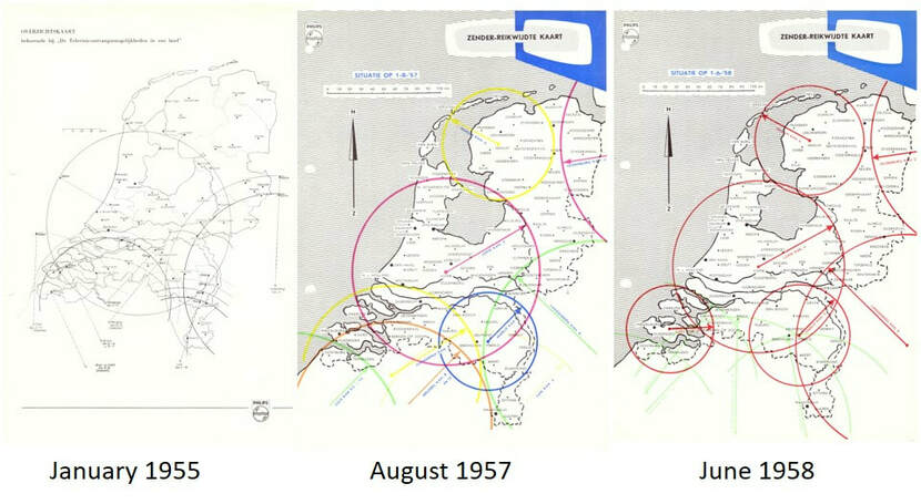
- On the left the situation until 1956: one single TV transmitter in Lopik, channel 4 VHF-I, covering central Netherlands, but not more than 40% of the country. People living in the province of Zeeland and western brabant could receive the Belgian BRT on channel 2 if they had a multi-standard receiver. People living in the south-east of the country could receive the German Langenberg transmitter on channel 9 VHF-III. But the upper 30% (all of Friesland, Groningen and Drente) couldn't receive any channel!
- By August 1957 two additional transmitters were installed, both medium power. Mierlo covered part of (but not all) of south-eastern Brabant and Limburg on channel 5 VHF-III, Insum covered Friesland on channel 6 VHF-III. Large north-eastern parts of the country still had no Dutch station coverage, although they could watch the new high power German transmitter in Oldenburg (channel 2).
- By June 1958 Zeeland had its own transmitter at Goes, channel 7 VHF-III. (As a side note, this was the same transmit tower from which my father did his Ku-band transmitter experiments in 1958. See here).
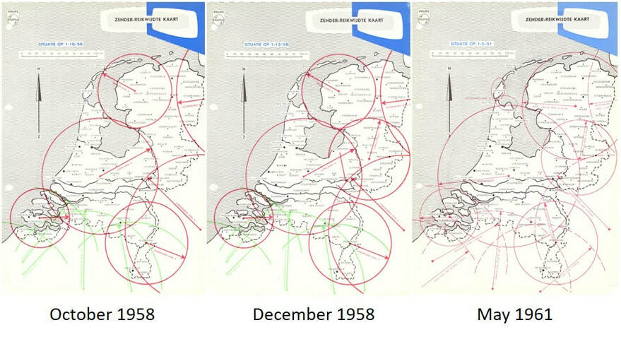
|
The next phase was one of optimization to provide TV to the entire country.
|
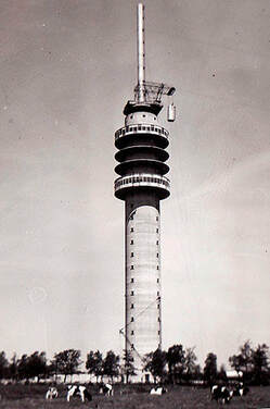
The TV tower in Smilde under construction in 1959. The concrete base was 100m high, the lattice tower on top became 200m high. [smilde.radio-tv-nederland.nl]
|
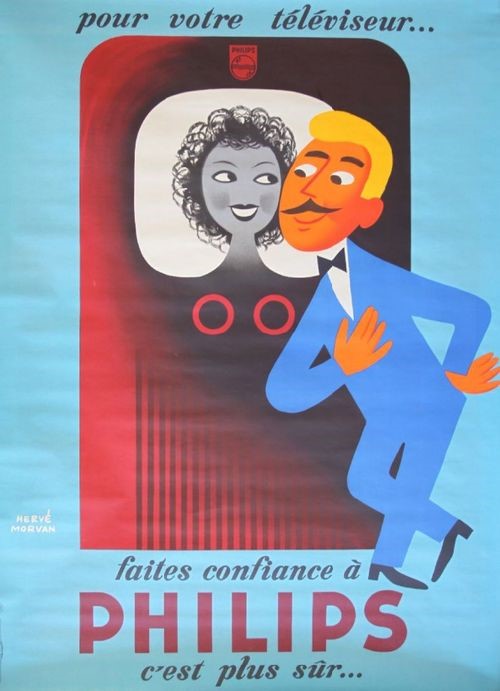
A 1953/54 French Philips TV advertisement. [Pinterest]
|
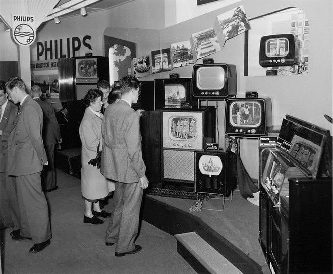
An interesting overview of the latest Philips TV models as exhibited in a shop or show during probably early 1954. Shown are the TX500 at the bottom, left of it the console TX1725A, to the middle right the Belgian multi-norm 17TX100, left above it the TX1720A and upper right the small TX1422. [Pinterest]
|
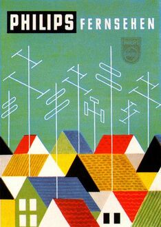
A 1955 Philips advertisement in Germany. [Pinterest]
|
Multi-standard reception, the 17TX100 platform, 1953
|
So far all television receivers discussed had been designed for receiving a single standard, starting from the "old" British 405 lines and French 441 lines, via the temporary 567-lines Philips standard to the final (CCIR-B) 625 lines and French 819 lines. Because the 625-line standard covered by far the largest part of Europe it was the dominant one in this history. At the same time we have seen that the outcome of the 1951 CCIR effort for standardization was a mild chaos, with ultimately five standards in Western Europe. Especially Belgium with its two modifications of the 625-line and 819-line standards became a nightmare. The problem with such a result becomes most apparent at the boundaries between standards, where people on both sides of the border, especially when they speak the same language, want to watch TV programs from both sides too; Flanders-Netherlands, Wallonie-Luxembourg-France, Luxembourg-Germany, Switzerland-France etcetera. The only solution for this were "multi-standard" (also called multi-norm) receivers. The need for multi-standard receivers became urgent from 1953, when both Belgium and Switzerland started TV broadcasting, while in France the old 441-line system was being replaced by the 819-line standard. This is where the 17TX100 platform comes in.
|
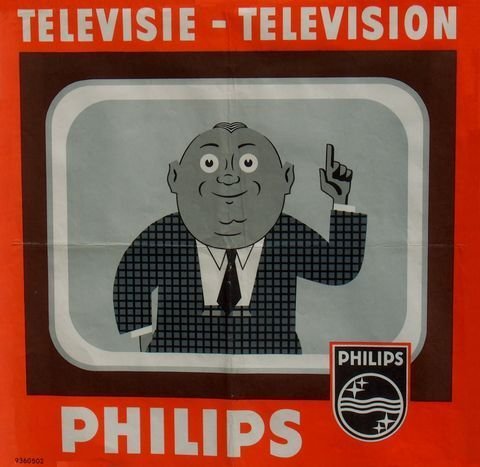
A bi-lingual Philips TV advertisement from Belgium, implicitly advertising multi-norm sets. [Affichegalerij.nl]
|
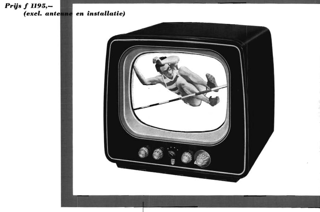
1954 advertisement for the 17TX100 multi-norm receiver. The central knob is used for standard-selection. The price at introduction was 1195Hfl.
|
The 17TX100 is a bit of an oddity. Seen from the valves used it was contemporary to the TD1720 platform, which means that the design started 1951, quite ahead of the time that multi-standard sets would be needed. At the same time it might well be that the Belgian TV broadcast introduction was originally planned much earlier but substantially delayed. Whatever the reason, the formal launch was after mid 1953 as indicated by the latest product coding. The first models 14TX100 and 17TX100 were launched beginning of 1954, with next models in 1955-56 as indicated on the service manual. This meant that the platform used an older architecture, but recent components like the PABC80, DY86 and germanium diodes.
Making a 4-standard receiver was quite a challenge, especially the differences between the French 819-line standard and the regular 625-line norm were considerable. The resulting solution was deemed quite an achievement, and was published in the prestigious Philips Technical Review magazine December 1955 (Vol.17, No.6). To refresh ones memory, these norms were (using the later CCIR code) received by the 17TX100 platform: |
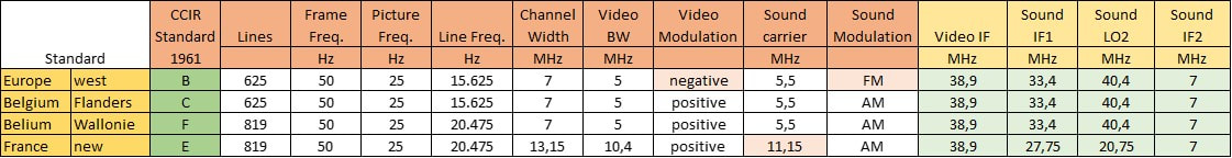
The four TV transmission standards that were received by the 17TX100 multi-standard set. The orange part describes the formal standards, the yellow part lists the implementation frequencies in the Philips 17TX100 set.
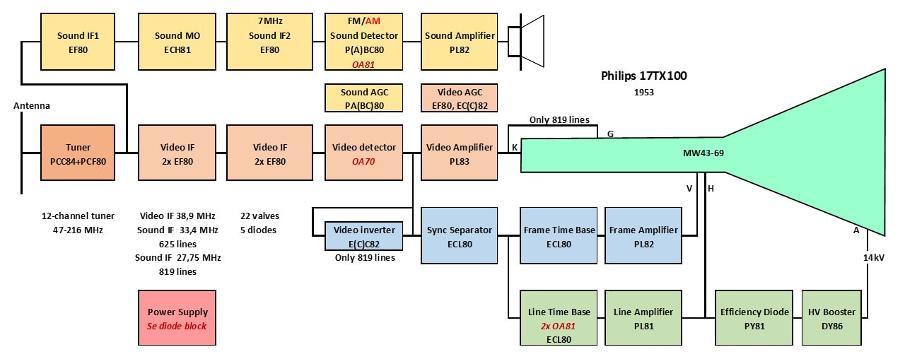
Block diagram of the Philips 17TX100 multi-norm TV receiver. It was capable of receiving standard 625-lines, the Flanders-Belgium 625-line standard with positive modulation and AM, the Wallon-Belgium 819-line standard with reduced video bandwidth and the regular 819-line French standard.
The following measures and modifications to a regular 625 line design were implemented to achieve a 4-norm receiver:
Serving the complex multi-standard situation for areas with multiple broadcast norms (Hong Kong was another famous one) has always remained one of the strengths of the Philips televisions.
- The tuner, based on the latest PCC84-PCF80 design, had the usual ten VHF-I and III channels 2-11 with an additional 11th channel covering the French system channels 8a and 8 of the Paris and Lille transmitters.
- Because of the large differences in IF frequency, the sound IF branched off immediately at the output of the tuner. Picture IF was 38,9MHz, which meant that the sound IF was 33,4MHz (B-C-E) or 27,75MHz (F).
- To harmonize the sound demodulation, it was decided to introduce an additional down-mixing step to a second IF of 7MHz. After an EF80 IF amplifier the triode of an ECH81 acted as IF oscillator with the heptode as mixer. The IF oscillator was switched between 40,4MHz (B-C-E, note that this is a higher oscillator) and 20,75MHz (F, this is a lower oscillator). As the PTR article explains these choices were based on interference analysis, keeping harmonics of the LO outside any RF video band.
- The sound detector could be switched between a regular PABC80-based FM ratio detector for standard B, or AM peak detection using an OA81.
- The sound branch had its own AGC, with the third diode of the PABC80 acting as peak detector.
- The video IF was a regular staggered tuning chain, with the modification that for norm F the lower frequency was decreased further, as well as the sound trap at the input. This switched the video passband between 5 and roughly 6,5MHz, so clearly not the full 10,5MHz official video bandwidth of the French standard. This will have given decreased horizontal resolution for this norm, which was probably deemed acceptable.
- The video output needed switching between negative and positive modulation. For negative video modulation (norm B) the output of the video power amplifier PL83 was normally fed to the picture tube cathode. For the positive modulation standards the video output eas instead connected to the picture tube gate, introducing an additional inversion. For the connection to the sync separator a similar approach was taken: the negative modulation signal was directly fed to the standard sync separator ECL80. The positive modulation signal was taken from the PL83 cathode (and thus inverted compared to the anod output, and buffered by a grounded base section of an ECC82, again not introducing any inversion. This resulting not-inverted postivie modulation signal (thus equal with respect to sync pulse polarity to the inverted negative modulation in norm B) was fed to the sync separator.
- In the line time base oscillator and flyback transformer there were four switches to select between the 15.625kHz (B,C) and 20.475kHz (E,F) line frequencies.
- To save further on valves the platform introduced a selenium diode stack as rectifier for the power supply. This limited to the total number of valves to 22.
Serving the complex multi-standard situation for areas with multiple broadcast norms (Hong Kong was another famous one) has always remained one of the strengths of the Philips televisions.
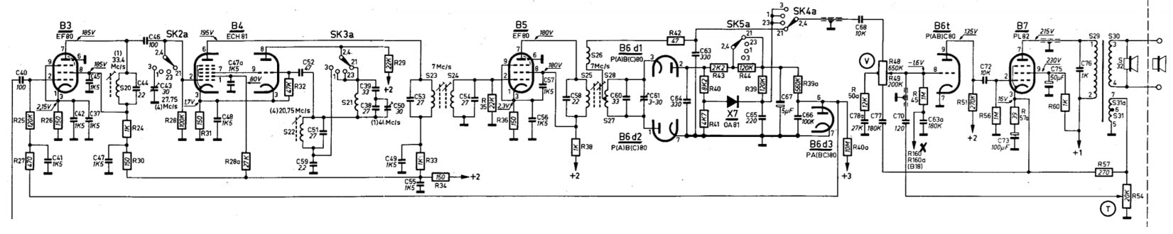
The audio chain of the 17TX100 showing how the set switched between the four standards. SK2a-SK5a are all shown in the position CCiR-B and switch in the order B-C-E-F. SK2a switches the IF BPF for norm-F from 34,4 to 27,75MHz; SK3a switches the IF oscillator for norm-F to 20,75MHz; SK4a selects for norms C-E-F the AM peak detector outpit; SK5a changes the AGC gain setting for FM.
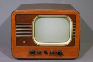
The Philips 14TX112 4-norm set from 1955. [Antique-TV-Blazianu]
|
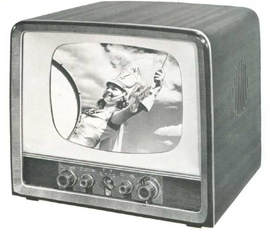
The Philips 17TX112A.
|
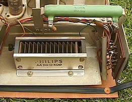
The stack of selenium rectifiers used as rectifier diode for the power supply. [MarcelsTVMuseum.nl]
|
The first high end set, 21TX140A, 1955
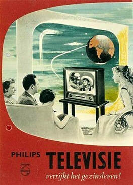
"Philips television enriches family life", an advertisement from 1954. [Pinterest]
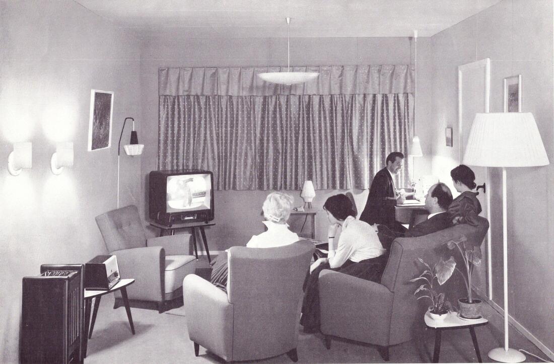
How to optimally light your room when watching TV, lighting advice by Philips. the set is a 21TX140 from 1956. Note the 1950s interior decoration!
|
The last element missing in the television portfolio was a high-end model. So far high end models essentially meant that a basic chassis was put into a large console or cabinet, preferably with doors, a large speaker and if necessary a radio, like the 17RD1422. But despite the undoubtedly higher price the customer didn't buy a TV with better performance than the basic model. The 21TX140 platform was the first time a family of sets was launched that also offered better electrical performance, justifying a higher price even in a normal sized cabinet. The TX140 platform seems to have been designed by 1954 in the Eindhoven Apparaten Lab, and was as mostly from this development centre intended for export. It must have hit the market by 1955. It seems there was a rapid succession of types, because by 1957 the 21TX144A-04 was in production as well as the 21TX145A. With every model more features had been added and 21" had become the standard screen size. As always platform designs were transferred to the regional television development groups, where especially in Krefeld the 17TD140 and 21TD140 family became a major runner. For several reasons I will now close this story on the television development by Philips with the 21TD144A Leonardo Luxus. Firstly because it is the most high end TV after ten years of television set development, and therefore a fitting point to stop. Secondly it is the second vintage TV set I possess, together with the home-built set of my father, and jointly they appropriately mark the ten years of TV development I intended to cover. And thirdly its year of production, 1958, is the year I was born, so another symbolical year to start focusing on other developments.
The original 17TX140 platform from Eindhoven and the 17TD140 from Krefeld had still differed slightly, but with the 21TX144 and 145 vs. the 21TD144 differences had become minimal, mostly linked to locally produced modules like the tuner. And the fact that the 21TX144 had a record four UY85 rectifier valves for the power supply, which had been reduced to the normal two valves in the 21TX145 and 21TD144. The 21TD144 can thus be treated as the representative ultimate model of the TX/TD144 family. As a last historical note it is interesting to know that the 21TX144/12 version (from probably 1958) was the first Philips TV using printed circuit boards! |
|
The high end character of the 21TD144 was achieved through a number of improvements, mainly 1. better sound 2. more advanced control loops for optimum picture performance and 3. more control switches. Before we dive into these characteristics, first a short analysis of the valve developments. The TX144 introduced a number of new valves:
|
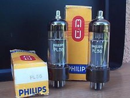
The PL36 power pentode. [eBay]
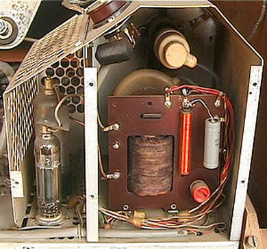
The 18kV high voltage enclosure of the 17TX144A, with on the left the PL36 (behind) and the PY81 booster diode. On the right above the line output transformer the DY87 in its isolated socket. [Marcels TV Museum.nl]
|
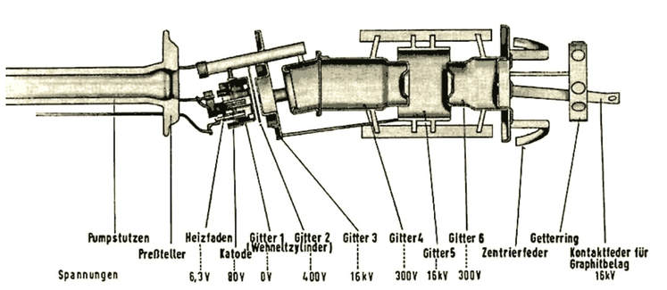
The internal electron gun, focussing assembly of a 90degrees AW53-80 picture tube. The grids g4 and g6 were for the electrostatic focus control. The slanted alignment of the cathode and Wehnelt cylinders is related to the ion trap. [Radiomuseum.org]
With respect to new features and functionality we'll use its TX1720 predecessor platform, from 1952 and in the period 1953-1955 the most high end set available from Philips, as the reference. The most important innovations were then as follows:
- Output Transformer-Less (OTL) audio power amplifier. This was an entirely new concept, where the bulky output transfer could be deleted. Although the first publication that triggered this development was not from Philips - by Petersen and Sinclair in 1952, although their publications was still using transformers - it was picked up and further optimized by the company. The basic idea is to make a push-pull output stage but without the availability of opposite polarity devices (like today an NPN and PNP transistor). There are two ways to do this. The first is to use two power pentode output valves (here PL84) which are connected in series, and drive the two gates in anti-phase. The point between the anode of the lower valve and the cathode of the upper valve is then much lower ohmic than a classical anode output. This "full-OTL" would come later in the early sixties, but the first implementation was a "light-OTL" where the upper valve was not driven and effectively acted as a constant current source load of the lower valve. The common node between the two output valves was AC connected to g2 of the upper valve, which drove the series connected loudspeakers. The output impedance was much lower than in a classical amplifier, but still 800Ohm. The breakthrough was that Philips developed 400Ohm speakers, of which two were serially connected. One was a large bass speaker mounted on the sidewall of the cabinet, one was a smaller treble speaker mounted on the front panel below the picture tube. As can be seen from the circuit diagram, the voltage on the cathode of the upper valve is 107V, and this requires a valve that can withstand such a high cathode-to-filament voltage. Later Philips would introduce the EL86/PL84 specially designed for this parameter. This concept provided excellent sound volume and OTL would remain a Philips high performance differentiator for many years to come. OTL was almost simultaneously introduced in the Philips radios and audio amplifiers from 1954 onwards.
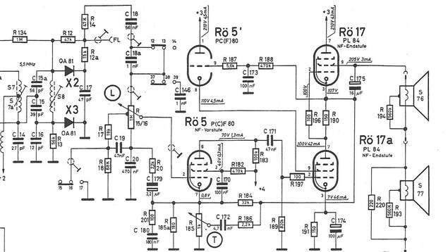
Circuit diagram of the audio output stage of the 17TD144A-04 and 21TD144A-04. valve 17a and 17 form the OTL output stage; valve 5' is the control loop for low distortion; switches 12-13-14 and 15-16-17 select between speech and music; switch 37-38-39 is for noise suppression; point FL is the connection of the volume remote control; L is Lautstärke (volume) control; T is Ton (tone) control.
- Diode-based FM-detector. After some "last model trials" on previous platforms, the TX/TD144A was the first to structurally introduce the diode-based frequency discriminator. Note by the way that it is no longer a ratio detector as used before in combination with the PABC80, but a Foster-Seeley type, with the two diodes again parallel. Apparently Philips had finally obtained a license for this concept (from Telefunken), the license had expired or they simply didn't care any more.
- Distortion control. For further optimization of the output stage performance, especially to guarantee the Total Harmonic Distortion (THD) remains sufficiently low, a control loop is implemented using a triode from the PCF80 that makes the setting of the lower pentode independent of the upper pentode and the component tolerances.
- Tone control in the 21TX144A was via two separate potentiometers; one for bass and one for treble. In the 21TD144 this has been replaced by one broad tone control in a feedback loop from the output to the PCF80 driver, in combination with a switch that selects between Speech and Music modes.
- Noise reduction. Switch b (contacts 37-38-39), linked to a similar switch in the video chain, improves noise reduction through s a low pass filter using C146.
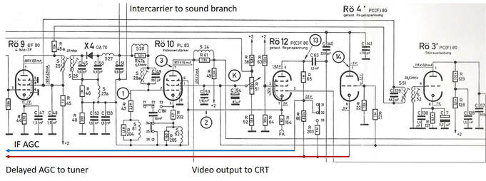
The video processing chain also contained a number of advanced control functions. The video detector X4 using an OA70 germanium diode, followed by an IF blocking filter (S28-R47a) towards the g1 of the video power amplifier is fairly standard for the period. The 5,5MHz intercarrier sound signal is tapped off across C151. To avoid the intercarrier signal coming into the video chain an additional 5,5MHz blocking filter S28a-C49 is positioned before g1 of the PL83 and via R61-S24 to the synchronization splitter. The anode of the PL82 video amplifier is directly connected to the picture tube cathode. The new functions are:
- Contrast switch. With switch a (contacts 21-22-23) an additional capacitor C181 is connected across the PL83 cathode, creating a high-pass filter for more contrast in the video picture. Normal contrast control is via R51 which controls the g2 voltage of the video amplifier and thus the gain of that valve. The remote control contrast controller is connected to the same node through the resistor R154.
- Split stepped AGC. The pentode of valve 12 and the triode of valve 4 form a stepped AGC controller each. The pentode controls the first three IF amplifiers (except the fourth one, valve 9). The reference is taken from the cathode resistor of the third stage and connected to R66 as well as the cathode of the triode AGC stage. The cathode of pentode 12 receives the video output signal of valve 10, while the anode is connected to the blanking sync pulses from the line output amplifier. This guarantees that the AGC only operates during the sync pulses and fly back, and only controls the sync level independent of the video content. The controlled anode voltage is fed back via frequency divider R5-R66 to the three IF amplifier g1 bias voltages. The triode valve 4' works roughly according the same principle and controls the g1 voltage of the PCC88 RF input amplifier, but starts later.
- Noise suppression. With switch b (contacts 34-35-36) an additional low-pass feedback impedance is inserted into the cathode of the PL82, giving more feedback and lower amplification for especially the higher frequency content of the video signal. Simultaneously contacts 31-32-33 switch R203 parallel to R66, effectively halving it and reducing the AGC loop gain by two.
- Interference suppression. The triode valve 3' detects interference impulses directly in the IF signal in a band around 35,5MHz. It is not entirely clear to me why there, other than that it is the frequency range between the upper edge of the video band and the sound at 34,4MHz. I assume that any signal detected there above a certain threshold is interpreted as (wideband) interference due to e.g. spiky noise. When signal is detected it directly pulls down the control grid g1 of the AGC control pentode valve 12, thus reducing the gain.
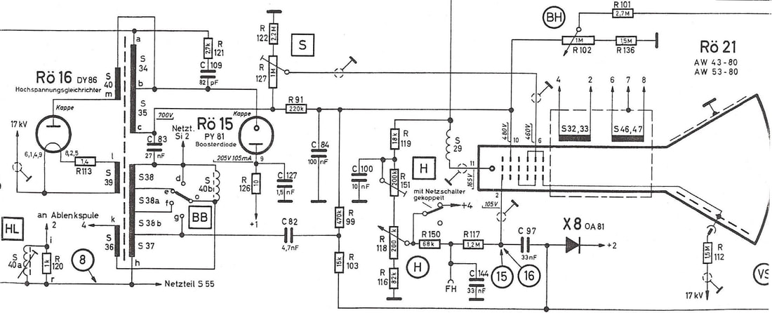
The line output and picture control section of the 21TX144A. HL=horizontal linearity, H= Helligkeit (Brightness), S= Schärfe (Focus), BH= Bildhöhe (picture height), BB= Bildbreidte (picture width); FH, the point between R117 and R150 is the control input for brightness from the remote control.
The last set of new controls was around the line output stage and picture control.
- Focus control. As mentioned, the new AW series of picture tubes featured electrostatic control through the additional grids g4 and g6. With the potentiometer R127 a voltage divider reduced the 700V of the line output transformer secondary to around 480V, which was directly connected to the g4-g6 focus grid.
- Brightness control in two steps. The fixed potentiometer R151 sets the point of maximum brightness, while with the front panel R118 the user can then reduce brightness as preferred. Brightness is also accessible for the remote control at point FH.
- Anti burn-in. To avoid that, after switch-off of the set, the undeflected spot burns into the phosphor at the centre of the picture screen, a switch is inserted between the +4 supply voltage and the g1 supply of the picture tube. This switch is connected to the main on-off switch and will interrupt the electron beam at switch-off of the receiver.
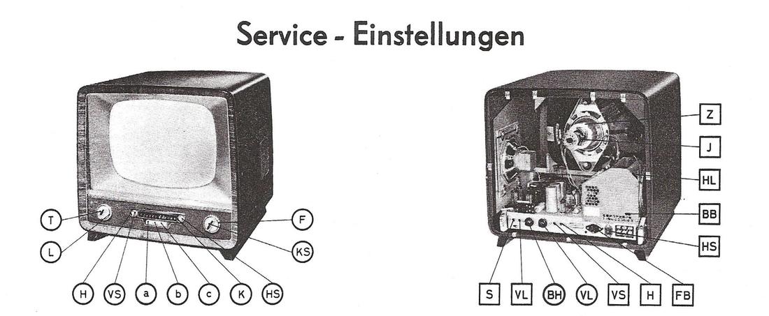
All controls on the Philips 21TD144A. From left to right:
T=tone, L=volume and main on/off switch, H=brightness, VS=vertical synchronization, a=high/low contrast, b=noise suppression on/off, c=sound speech/music, K=contrast, HS=horizontal synchronization, KS=channel selector, F=fine tuning channel, S=focus, VL=vertical linearity course, BH= picture height, VL=vertical linearity fine, VS=vertical synchronization preset, H=brightness preset, FB=remote control cable socket, HS=horizontal synchronization preset, BB=picture width, HL=horizontal linearity, J=Ion trap alignment, Z=picture centering. [Philips 21TD144A Service Manual]
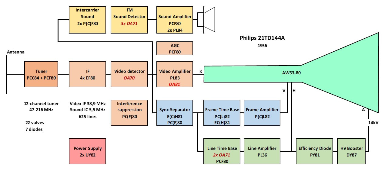
Block diagram of the Philips 21TD144A, which was the high-end television platform of the 1956-1958 period. It had a lot of additional control features and introduced the 21" AW53 picture tube.
A last feature worth mentioning is the remote control that was introduced around this time, as it looks especially in Germany, because the TX144 models didn't offer this feature, whereas the TD models consistently did. To be fair, it was not introduced with the 21TD140 platform but one earlier , the TD1720. It was, for all clarity, a wired remote control, where a small panel with three potentiometers was connected via a 4-wire cable of a few meters to a connector on the back panel of the set. All controls have already been introduced above: FL a 200kOhm potentiometer for Audio Volume (Lautstärke), FH a 1MOhm one for brightness (Helligkeit) and FK a 300Ohm potentiometer for contrast (Kontrast). In all cases the remote control resistor more or less by-passes the regular control network. The remote controls had no dedicated product name, only the regular Krefeld component number KR387-55.
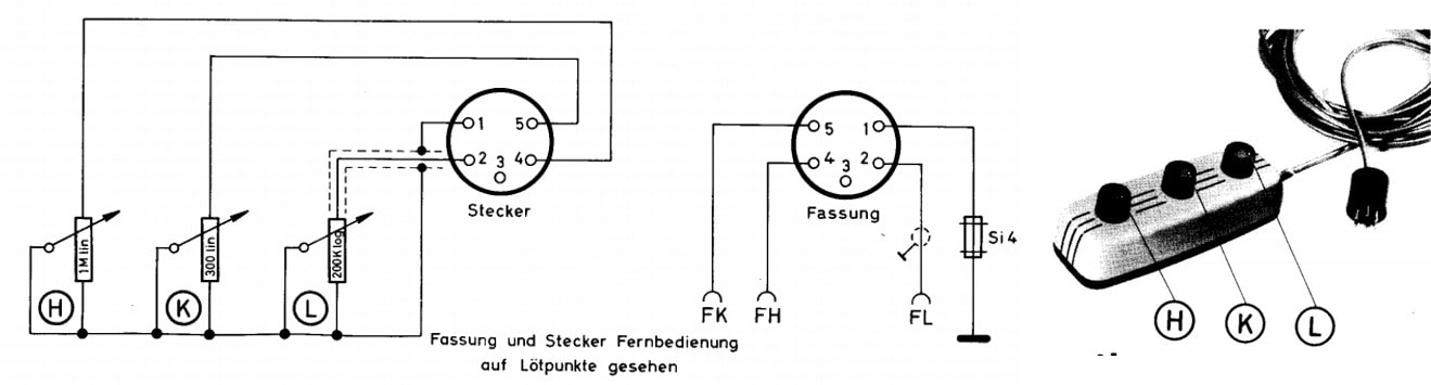
The KR 387 55 wired remote control for the 17TD140 and 21TD140 family of television receivers. [Philips Service Manual from Radiomuseum.org]
The second come-back of Protelgram, 1957
Earlier this chapter it has been shown that Protelgram, the MW6-2 high intensity picture tube and its Schmitt optical assembly, did not succeed in making rear-projection the winning technology for larger screen TVs. Picture tubes became the winner there, and the 1951 set TD2314 was the last TV set using this technology. However, as already mentioned earlier, Protelgram apparently had its staunch supporters within the Philips organisation, and its use was again not completely ended. The next application was projection TV! Before we come to that, we need to make a small sidestep to an earlier follow-up development of Protelgram.
|
In 1949, so at the height of the original Protelgram development and launch, the HIG Elektro-Akoustiek (ELA, Electro-Acoustics) started development of a large screen TV projection system. ELA made all non-consumer audio and video equipment: microphones, public address amplifiers, cinema and theatre equipment and more, complementary to the HIG Apparaten that covered radio and TV and domestic appliances. The Philips Eindhoven TV studio for the experimental transmissions and the associated TV camera development also were part of ELA. This development was again done in co-operation with Philips Research, the group of Haantjes that also supported TV developments. It required an even stronger high-intensity projection tube, which became the MW13-16, having double the radius and four times the area of the Protelgram MW6-2. However, it required the very high anode voltage of 50kV. It seems that the tube development was a regular engineering job in the HIG Elektronenbuizen, but the 50kV supply development required NatLab involvement.
The resulting system, formally the EL5750 but baptised "Mammoth", was indeed a volumunous apparatus, a large central console housing the optical unit with two wings for the electronics. For the 50kV unit it used four EL34 time base oscillators and four cascaded EY51s. The device displayed a 4x3 meter picture, not spectacularly large, but probably the largest one could get at the time. It was first presented as prototype in Berlin, October 1951, probably during the Funkausstellung, and launched in Turin, Italy, a year later. Interestingly, in 1953 in Paris a first 819-line version was demonstrated. It is not known what the real business success was of the EL5750, and how many were produced. However, ELA definitely continued with large video projectors and the MW13-38, successor of the MW13-16 tube, was still in the Philips Data Books as late as 1978! |
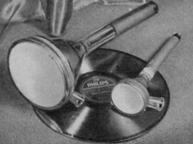
The new MW13-16 (left) and predecessor MW6-2 (right). [Radiomuseum.org]
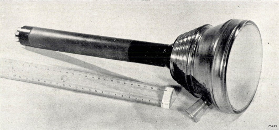
The new MW13-16 projection display tube. [Philips Technical Review Vol.15, 1954, p.27]
|
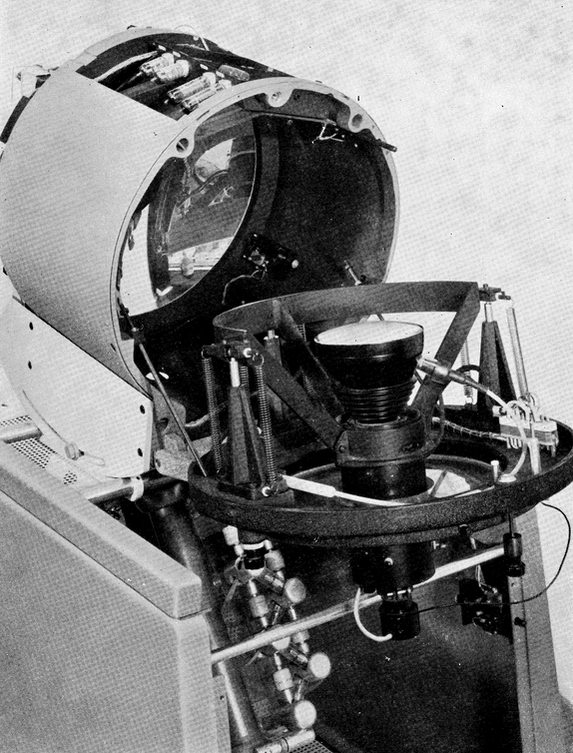
The opened optical unit of the EL5750 Mammoth, with the MW13-16 clearly visible as well as the large reflection mirror.
|
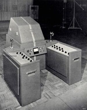
The EL5750 projection TV console. The left wing contains the TV receiver, the right wing the deflection control. [PTR Vol.15, 1954]
|
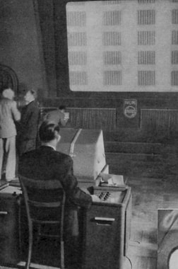
An operator taking care of the on-screen alignment of the EL5750 image. [Radiomuseum.org]
|
|
We made a small excursion to the EL5750 not only because it was an interesting piece of engineering, but because it was the first wall projection TV, albeit a professional one. As a next step, however, the same principle was applied to the consumer application. Re-using, surprise-surprise, the original MW6-2 Protelgram module, which was by now (1956 when development started, 1957/58 when the first product was released) well over eight years old. But as far as I can see from the service manuals it was really the same as used in the earlier rear projection sets. Whether these modules came from the old Protelgram stocks or that somewhere in the dungeons of the Philips organisation a limited Protelgram production continued is an interesting question I can't answer (yet).
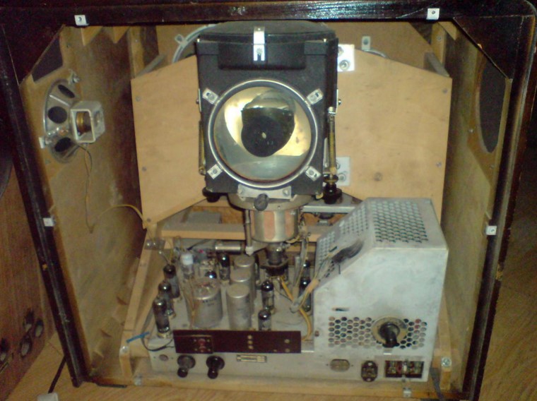
Interior view of the projection output (back)-side of the Philips VE2600 video projector. At the bootom the almost unmodified 21TD140 frame, above it the Protelgram optical module. [Radiomuseum.org]
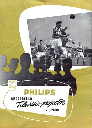
Advertisement for the VE2600. [Philips reclamkunst]
|
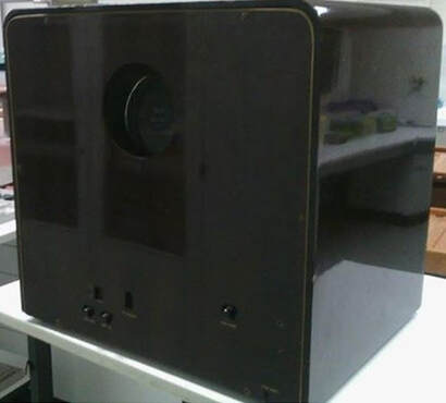
Exterior view of the Philips VE2600 projection TV, with the projection lens visible through the hole in the sets back side. [Radiomuseum Vechta, via Radiomuseum.org]
It seems that ELA, the same organisation that built the Mammoth, asked the TV factory in Krefeld to develop a projection version of their best and latest platform, which was the 21TD140. (It re-used the 21TD140 except for the frame time base oscillator that used the ECL80 from the 21TX100). The picture tube was replaced by the backward facing (!) Protelgram module, while the 25kV high tension sub-frame was mounted between the main frame and the front, next to the tuner module. This sub-frame was 100% identical to the one used in the TX701 six years earlier, but apparently deemed robust and fit-for-use. The optical module was mounted onto a wooden frame that was attached to the TVs interior construction. The only difference with the previous rear-projection sets was that a DAF96 protection valve was added to switch off the supply in case of problems.
The product was launched as the VE2600 Video Projektor, and sold together with a white display screen that could be mounted to the wall. The projected picture will most likely have been in the order of 100x75cm. The VE2601 version also had a video baseband input. As far as I can see the VE2600 was the first user of the VE family code, which was from that moment on used for 19" rack-mounted studio equipment. Surprisingly, at exactly the same moment (1957/8) that Philips ELA launched its VE2600, the German competitor Saba released the Saba Telerama P716, based on the same Protelgram unit. This makes one wonder who was first: did Philips start a broad sales campaign of its Protelgram modules, both and internally and externally? Or did ELA hear, through the Protelgram sales channel, of the Saba intentions and quickly asked for an internal solution? In any case the Protelgram module went through its third sales wave since 1949, this time for projection TV. Next to Philips and Saba other users were Italian SIT (the UG4060) and Prestel (TV45 and TV60) and the German company Panka.
And still Protelgram and its MW6-2 tube were not end-of-life, because in 1961 ELA launched the VE2609, what could be called a first professional beamer. The content was still the same, although upgraded with the latest TV chassis and a UHF tuner. This means that the technology must have lived for a number of years more. Who would have thought that when Protelgram was declared "dead" in 1949?! |
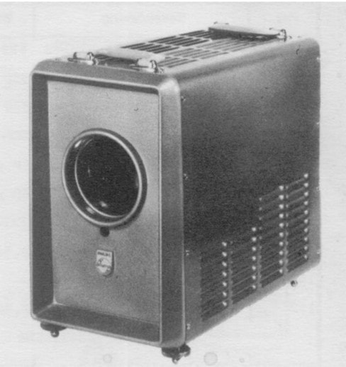
The Philips ELA VE2609 from 1961, what looks the first real beamer. [Radiomuseum.org]
|
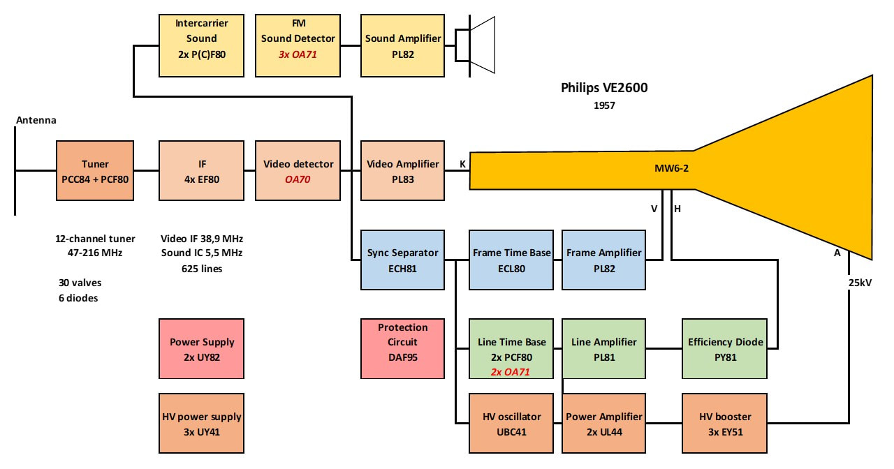
Block diagram of the Philips ELA VE2600 video projector, based on the 21TD140 chassis.
|
Summary and some Conclusions
|
After the initially humble take-off in the years between 1948 and 1953, since then TV production volumes at Philips showed a steady growth. In 1954 the 500.000 sets/year mark was passed and in 1958 the 1 Million/year. Also in Philips home country the Netherlands growth finally kicks in: from 16.000 sets in 1954 to 80.000 in 1956, and tripling again to 240.000 in 1958. This growth would continue almost unchanged until well in the seventies, when the global TV market reached a plateau of some 120Mio sets per year.
|
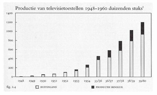
Production of television sets 1948-1960 in thousands/year. Black = production in the Benelux (read Netherlands), grey= production abroad. [Geschiedenis van de Koninklijke Philips Electronics N.V. pt.5]
|
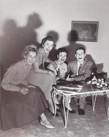
A fitting close of this story, with a 1956 television advertisement of Philips. A TV (from Philips, obviously) simply makes you happy. Funny enough from an age, hair style and clothing perspective these happy people could have been my parents!
|
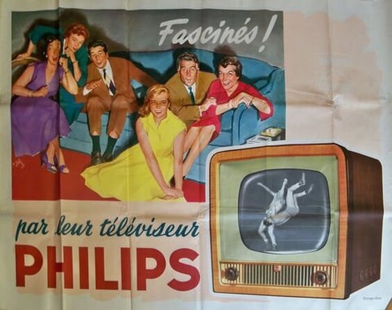
In France and Belgium-Wallonie people were equally happy with a Philips TV! The set seems to be a TF1765 or similar, from 1956. In analogy to the left picture, the happy people on the couch should be my parents-in-law. [Affichegalerij.nl]
|
This chapter on the history of Philips television development started with the introduction of 625-line television broadcasting in 1949. Eight years later, Philips television had grown to a full and broad portfolio of products: the 17TX110 mid-end platform (although at the end of its production life), the 17TX120 low end platform and the 21TX140 high end platform. With the 17TX100 multi-standard to fill the complex areas, next to the single-standard sets for France and Britain. All in all a very broad portfolio, and it had made the company one of the leading players in Europe with also some modest footholds in other areas like South America (Brazil and Argentina).
In these ten years we've seen a remarkable string of innovations and technology steps. Most importantly in the key electronic components; the radio valves and the picture tube. We've seen the use of at least four generations of valves: from the large pre-war E30 series in the Research set via the Rimlock E40 and U40 in the first products to the Noval E80 and then the P80 families. One of the success factors for Philips was the tight and exceptionally good cooperation between Research, the Radiobuizen Lab of the HIG Elektronenbuizen and the Apparaten Lab of the HIG Apparaten. The first drove the definition and development of new optimized valves, including reference for optimal application. The Apparaten Lab, where the set development took place, mostly used those new valves immediately, often based on the RBL reference designs, to quickly release a next improved generation. The speciality of the RBL was to define new combination valves like triode-pentodes that optimally fitted the system partitioning of the TV sets developed by the AL. The PABC80, ECL80, PCF80 and PCL82 are good examples of those, but also the EY51 and EF80 that were used for many years. This made it possible to develop ever more advanced televisions without the valve count exploding, On the contrary, it is remarkable to see that the valve count of a regular television has over these ten years hovered around 21-22, sometimes 1 or 2 higher for high-end, up to 5 lower for low-end. In between were only the continuing but ultimately unsuccessful efforts on rear projection TV, having valve count up to 32-33. But as we've seen also the developments of the picture tube went very fast, by 1953 17" had become standard and by 1956 21", effectively killing the concept of projection TV.
In these ten years we've seen a remarkable string of innovations and technology steps. Most importantly in the key electronic components; the radio valves and the picture tube. We've seen the use of at least four generations of valves: from the large pre-war E30 series in the Research set via the Rimlock E40 and U40 in the first products to the Noval E80 and then the P80 families. One of the success factors for Philips was the tight and exceptionally good cooperation between Research, the Radiobuizen Lab of the HIG Elektronenbuizen and the Apparaten Lab of the HIG Apparaten. The first drove the definition and development of new optimized valves, including reference for optimal application. The Apparaten Lab, where the set development took place, mostly used those new valves immediately, often based on the RBL reference designs, to quickly release a next improved generation. The speciality of the RBL was to define new combination valves like triode-pentodes that optimally fitted the system partitioning of the TV sets developed by the AL. The PABC80, ECL80, PCF80 and PCL82 are good examples of those, but also the EY51 and EF80 that were used for many years. This made it possible to develop ever more advanced televisions without the valve count exploding, On the contrary, it is remarkable to see that the valve count of a regular television has over these ten years hovered around 21-22, sometimes 1 or 2 higher for high-end, up to 5 lower for low-end. In between were only the continuing but ultimately unsuccessful efforts on rear projection TV, having valve count up to 32-33. But as we've seen also the developments of the picture tube went very fast, by 1953 17" had become standard and by 1956 21", effectively killing the concept of projection TV.
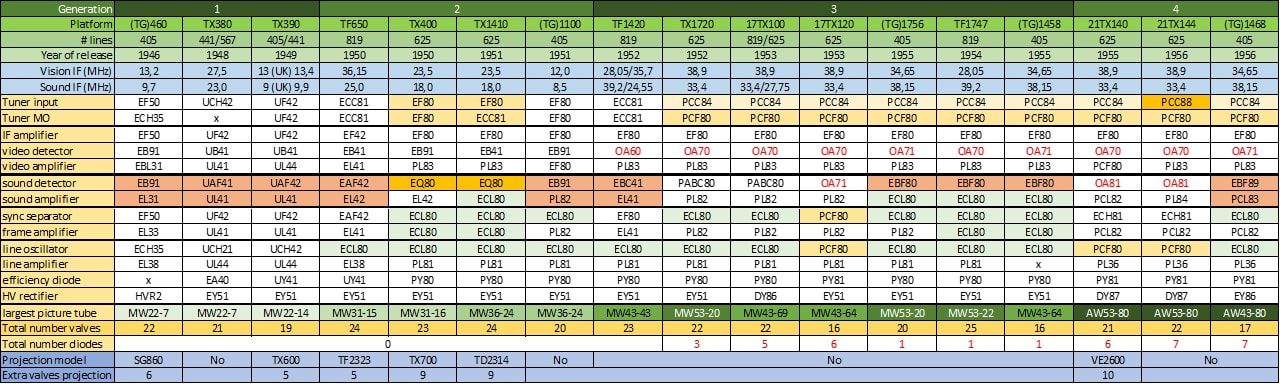
Overview of the television platforms developed by Philips between 1946 and 1956. For each of these platforms the valves used for some of the critical functions inside the TV are listed, showing the evolution of valves used over the years. Yellow boxes on the tuner rows indicate real tuner modules. On the sound rows the orange boxes indicate AM sound. At the bottom the (rear and front) projection versions of each platform are listed, and their number of additional valves. In general the valves and valve count are typical for the platforms as indicated. However, especially within long running platforms or in case of added features there could be slight variations.
The generation overview in above table allows for some observations:
As explained, I had started my research into the history of the Philips television development triggered by the home-built TV of my father; I simply wanted to understand how it was designed and from which activity it was born. It was only when trying to make logic from the limited information I had plus what I could find on the internet that slowly the bigger picture became clear. So one of the surprises was to find out that well before the TX400, often called the first Philips TV, in the 1948-49 period already quite some models were produced, although only for the British and French markets. Next I had a major struggle to understand how the 567-line TX594 played in all this, and ultimately how it was converted from 567 to 625 lines as part of that standard conversion. Once that was done it became evident I had to look at all developments in terms of platforms and that the valves used were the key to understanding and categorizing those platforms. Because the number of sets that Philips developed in the period covered is remarkable, and it was only after figuring out the product coding principles and the valves used that the platform structure became evident, the table above is only a summary of the much bigger table I made for this purpose. While doing all this I stumbled upon incredible sources of data and knowledge. Radiomuseum.org with its massive database of television (and radio) sets and their characteristics. Expert forums of valve and radio-TV hobbyists in the Netherlands, Germany, Britain and France, where many technical issues I bumped into had been discussed and resolved. And I came into contact with people like Ronald Huisman through his site Technisch Museum, who made astonishingly beautiful restorations or rebuilds of the TX400, TX500, TX700 and TX1410. Or Albert Zwaagstra, who to my total amazement has rebuilt the home-built television my father had built in 1948! And after the first upload Jac Janssen told me has a working SX861 from 1947 (!!), which, based on his info, made it possible to re-write that whole section. Both Jac and Mans Veldman provided me with a copy of Jagers booklet on an Experimental Television from 1949, which refined the story on the transition from 567 to 625 lines. At the same time I continue to receive new, additional or corrective inputs, so the story is never complete but hopefully continually improves and becomes more accurate. The latest surprise was of course when I was contacted by Taco Vonk, who stumbled on this site and invited me to photograph the very first ever TV set made by Philips in 1935 in the collection he supervises. Which made that I had to re-write the entire pre-war part of the story.
This is where I'll stop for the moment. Starting from the late 1950s television really started booming, with Philips as a leading European and overseas player (South America, Middle East, South Africa, Australia and New Zealand and many countries in South Eastern Asia). Both the number of production factories exploded as well as the product portfolio, and describing those Philips television developments requires a different approach than the set level one taken so far. Which seems a bit too ambitious to take on as a challenge at this moment. However, you can find the bigger picture on the Philips television developments as a side story to my Philips Tuner history pages. Examples are:
I think it has become an interesting (and pretty long) story, which is at the same time by far not complete. There are still quite some white spots, e.g. on the organization of the Apparaten Lab, while it would also be interesting to know more about the television factories. But the original ambition with which I started off, to find out how and where the homebuilt television of my father fitted in the Philips television development, has largely been answered. The conclusion is that he was - of course - a very modest element of the rapidly growing integral Philips activity on development of television and its key components. But it was in the middle of an exciting and critical period, and as such has given (me) a lot of insight into what happened back then, today 70 years ago. And it makes me all the more happy and proud that, thanks to my late father Piet, I'm in the possession of an original home built TV from 1948!
Like for the EQ40-EQ80 story I invite anybody with corrections or additions to contact me, such that I can improve the story where needed. I plan to upload updates whenever I have useful additions. In the meantime I hope readers will enjoy the story on this piece of television and Philips history. Looking forward to any feedback!
- It took till the 3rd generation TVs to have the IF settle on their final values. Especially UK sets stayed with very low IF values until 1951/52.
- Whereas tuners were introduced in Dutch and German sets from 1951 onwards, French and UK sets stayed until 1954/55 with single-channel non-tunable sets.
- The typical life time of a valve being used in TV design was 3 years, with a few exceptions of apparently very successful types: EY51 (1948-1955), ECL80 (1950-1956), EF80 and PL83 (1950-1956).
- Semiconductor diodes were introduced surprisingly early in 1952, only a few years after their discovery. However, the growth in use after that was slow, and by 1955/56 only a handful of them was used in a typical TV set.
- Rear projection was only used based on Gen1 and Gen2 platforms. The third generation TV, introducing the 17" MW43 picture tube effectively killed rear projection. And tehn briefly came back as wall projection TV.
As explained, I had started my research into the history of the Philips television development triggered by the home-built TV of my father; I simply wanted to understand how it was designed and from which activity it was born. It was only when trying to make logic from the limited information I had plus what I could find on the internet that slowly the bigger picture became clear. So one of the surprises was to find out that well before the TX400, often called the first Philips TV, in the 1948-49 period already quite some models were produced, although only for the British and French markets. Next I had a major struggle to understand how the 567-line TX594 played in all this, and ultimately how it was converted from 567 to 625 lines as part of that standard conversion. Once that was done it became evident I had to look at all developments in terms of platforms and that the valves used were the key to understanding and categorizing those platforms. Because the number of sets that Philips developed in the period covered is remarkable, and it was only after figuring out the product coding principles and the valves used that the platform structure became evident, the table above is only a summary of the much bigger table I made for this purpose. While doing all this I stumbled upon incredible sources of data and knowledge. Radiomuseum.org with its massive database of television (and radio) sets and their characteristics. Expert forums of valve and radio-TV hobbyists in the Netherlands, Germany, Britain and France, where many technical issues I bumped into had been discussed and resolved. And I came into contact with people like Ronald Huisman through his site Technisch Museum, who made astonishingly beautiful restorations or rebuilds of the TX400, TX500, TX700 and TX1410. Or Albert Zwaagstra, who to my total amazement has rebuilt the home-built television my father had built in 1948! And after the first upload Jac Janssen told me has a working SX861 from 1947 (!!), which, based on his info, made it possible to re-write that whole section. Both Jac and Mans Veldman provided me with a copy of Jagers booklet on an Experimental Television from 1949, which refined the story on the transition from 567 to 625 lines. At the same time I continue to receive new, additional or corrective inputs, so the story is never complete but hopefully continually improves and becomes more accurate. The latest surprise was of course when I was contacted by Taco Vonk, who stumbled on this site and invited me to photograph the very first ever TV set made by Philips in 1935 in the collection he supervises. Which made that I had to re-write the entire pre-war part of the story.
This is where I'll stop for the moment. Starting from the late 1950s television really started booming, with Philips as a leading European and overseas player (South America, Middle East, South Africa, Australia and New Zealand and many countries in South Eastern Asia). Both the number of production factories exploded as well as the product portfolio, and describing those Philips television developments requires a different approach than the set level one taken so far. Which seems a bit too ambitious to take on as a challenge at this moment. However, you can find the bigger picture on the Philips television developments as a side story to my Philips Tuner history pages. Examples are:
- the developments towards the (final) high Intermediate Frequencies
- Automatic Gain control
- French and Belgian multi-norm receivers
- Automatic Frequency Control
- Introduction of UHF reception
- IF and multi-standard TV in combination with UHF
- The introduction and development of Colour TV
- TV control mechanisms
- New French TV standards
- The larger Philips organisational and business developments
- The Philips TV organisation
- VCR
- IF developments, integration and SAW filters
- Integration and the one-chip TV
- Satellite TV
- D2MAC
I think it has become an interesting (and pretty long) story, which is at the same time by far not complete. There are still quite some white spots, e.g. on the organization of the Apparaten Lab, while it would also be interesting to know more about the television factories. But the original ambition with which I started off, to find out how and where the homebuilt television of my father fitted in the Philips television development, has largely been answered. The conclusion is that he was - of course - a very modest element of the rapidly growing integral Philips activity on development of television and its key components. But it was in the middle of an exciting and critical period, and as such has given (me) a lot of insight into what happened back then, today 70 years ago. And it makes me all the more happy and proud that, thanks to my late father Piet, I'm in the possession of an original home built TV from 1948!
Like for the EQ40-EQ80 story I invite anybody with corrections or additions to contact me, such that I can improve the story where needed. I plan to upload updates whenever I have useful additions. In the meantime I hope readers will enjoy the story on this piece of television and Philips history. Looking forward to any feedback!
References
- Piet Hooijmans private papers on his home-built TV set, containing the circuit diagrams I coded RBL1-RBL4, plus many handwritten notes on circuit modifications and some measurement graphs.
- Philips Research Philips Technical Review Volumes 1-13 (1936-1954). Digital copies can be found here
- Philips Electron Tube Division Electronic Application Bulletin volumes 10-16, 1949-1955.
- Philips Electron Tube Division Television Receiving Tubes EF80 ECL80 PL81 PL83 PY80, 1950
- Philips series Electron Valves, volumes I-VIII, published 1940-1953. (I have part I and IV, the others from the web)
- F. Kerkhof and W. Werner, Televisie, Philips Technische Bibliotheek, 1951 (I have the 4th edition from 1969.
- Philips Service Manuals of individual television receiver models; partly private collection, many found on the internet.
- Electron, the monthly publication of the Dutch Vereniging of Radio Amateurs, volumes 1947-1952. Was especially useful for the "external view"on the PET-period of experimental transmissions.
- I.J. Blanken, Geschiedenis van de Koninklijke Philips Electronics N.V., Europese Bibliotheek, Zaltbommel, 2002. Especially pt.4 "Onder Duits beheer" and pt.5 "Een industriële revolutie".
- A.A.A. de la Bruhèze, H.W. Lintsen, Arie Rip, J.W. Schot Techniek in Nederland in de twintigste eeuw. Deel 5. Transport, communicatie, 2002. Good background story on the broader development of television broadcast in the Netherlands. The on-line version can be found here.
- Sonja de Leeuw, De man achter de schermen, De televisie van Erik de Vries", Boom, 2008. An irritating and not so interesting book due to the boastful and often distorted stories of Erik de Vries, but neverhtless with some facts on especially the pre-war Television Caravan.
- Mark Burgess, History of Philips Semiconductors in the 1950's, 2009. On-line version can be found here.
- www.Radiomuseum.org, an incredible collection of documentation, pictures and forum discussions on both electron valves as well as radio, television and other electronic devices.
- www.technischmuseum.nl, the site of Ronald Huisman with (amongst others) the beautifully restored TX400, TX500, TX594 and TX1410. I have used many of his pictures with permission.
- www.radiotechniek.nl, the site of Albert Zwaagstra that includes - on page2 - the reconstruction of a home-built TV similar to the one of my father. Not exactly identical electrically, but very close. Impressive.
- www.marcelstvmuseum.com. Marcel's TV Museum, with a very large collection of old (Philips) TVs.
- www.DOS4Ever.com, the site of Ronald Dekker. Mostly on his famous tube tester, but also a lot of history on the Radiobuizen Lab and Research that was the inspiration and starting point of my investigations. Plus the nice EF50 history.
- Eindhoven in Beeld, a site with innumerable old and new pictures of Philips activities in Eindhoven.
- Nederlands Forum over Oude Radios
- UK Vintage Radio Forum , Repair and Restoration
- The Valve Page, no longer active but with a very useful overview of British TV sets by Philips and Mullard.
- Antique-TV's on the site of Nicolas Blazianu which contains much info on early Philips and Radiola models.
Update history
- First upload July 2017
- August 2017
Added section on pre-war and immediate post-war UK sets as bridge to the SG860/SX861
Re-written and extended the SX861 section based on all inputs from Jac Janssen
Added story on booklet by Jager on Experimental Television from 1949, of which I obtained copies from Jac Janssen and Mans Veldman.
Added section on French 819-line sets
Based on forum discussions checked and amended statements on FM demodulation concepts used
Update block diagrams with some technical details (RF and IF frequencies, valve and semiconductor count)
Added table of content per page with clickable links to the chapters
Added some nice pictures - December 2017
Update the standards tables (UK 405 predominantly vertical polarization, input from Peter Scott; French system channel bandwidth operationally 13,15MHz) - January 2019
From Jaap Verkade I received a full set of Service Documentation for the first generations of Philips TV sets, from the TX400 to the 23TX400 family. This also contained Service Notes explaining the TV transmitter situation at the time, which I've used to add a section on the TV transmitter deployment. - February 2019
Substantial update linked to the complete revision of pt1.
More details on especially UK generations added. - June 2019
Based on the info received from Edvard Paling I could add details on the first NTS studio in Bussum.
Furthermore some updates and corrections plus more pictures on the picture tubes. - April 2020
Minor updates. Have added nice pictures of the TF651 of Jac Janssen.
Have added picture of the OC70 transistor production process. - February 2021
Taco Vonk was so kind to show me around the radio and TV collection of Harry de Winter and himself, including the 563A, TX1410U, TF1146A, of which I have included some additional nice pictures. - August 2021
Have added a last section on the rear projection use of Protelgram, to close that story. EL5750 and VE2600.
And Simon Crawshaw pointed me at some high-quality pictures of the Tel6 and 1937 demonstration van.