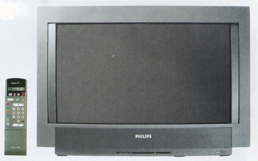
Introduction
|
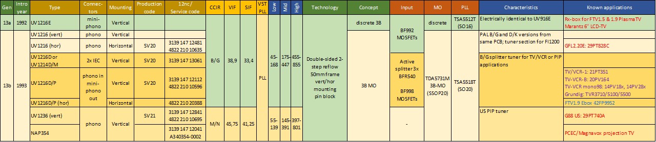
We have reached the end of the 1980s, probably the turning point in the Philips Tuner history. On the one hand the business has been doing well: constant consolidation of (mainly European and US) competitors has substantially increased the market share and volumes, making it one of the global top3 tuner makers. However, in parallel the emergence of Japanese competition has made the business environment increasingly harsh, with a serious pressure on profitability and thus cost. Although Philips with its UV800 tuner family has probably made the best tuner ever in terms of robustness and performance, this model is clearly too big and expensive and in the coming two decades we will see a continuous drive for cost reduction and the associated size reduction. One of the most remarkable steps in this context is the move to the World Standard Pinning (WSP), with Philips agreeing with its main competitors Alps and Matsushita on a common pinning. It will lead to severe market share loss with the internal Philips TV organisation and a disastrous price erosion.
At the same time business can be extended with RF modules for new consumer applications: video recorders and satellite set top boxes, while TV frontends (combination of tuner and IF) offer functional integration and thus higher value. In this next chapter we will see the appearance of more emerging applications: multimedia television frontends for the personal computer (PC) and, after the demise of the D2MAC and HDMAC analogue high definition TV standards, new digital TV standards emerge for satellite, cable and terrestrial broadcast. Other new application segments are less successful, like telephone modules. The microwave modules (LNBs for satellite reception) show impressive functional integration and performance improvements, even leading to 40GHz modules. All this against the background of continuing semiconductor IC integration, resulting in the first mixer-oscillator and PLL integration (the MOPLL). Simultaneous integration of the IF leads to TV-radio combo ICs. In fact, as we will see, the semiconductor content of the modules continues to grow, and performance and availability of ICs will become an increasingly dominant factor in the product definition, development and price setting of tuners and the other RF modules. One of the elements that required continuous attention was the manufacturing process, which had to deal with severe price pressure, ever smaller sizes of the modules and components, while simultaneously volume growth to (at its peak) almost 28Mio units per year. The industrial policy was thus a very important element of the BU Tuners activities. |
Chapter navigation
|
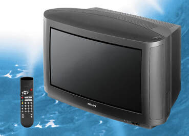
UV900, the new volume tuner, 1990
The previous Philips volume TV tuner generation was the UV600, introduced in 1985, using the solid one-piece Zamac frame and introducing the TDA5030 mixer-oscillator IC. The first models used were pre-scaler-based in the high end CTV sets (2A, 2B and 3A from the Brugge fab) but gradually the bulk of the models used became VST without pre-scaler, driven by the need for lower cost in the mid-end chassis (CP90, CP110, G90AE from Dreux, as well as the Overseas GR1AX chassis). The need for cost reduction lead to the parallel introduction of the 700-family, again in folded metal frames, of smaller size and with discrete MO. Whereas the high-end segment continued with the UV816 that introduced the full PLL next to the MO-IC, this covered only a fraction of the Philips TV volume: high-end volume was around 100k sets per year of the total 12Mio sets produced annually by Philips. It is thus obvious that the next tuner family for the mid- and low-end segments had to provide a serious cost reduction compared to the UV60o/700, not to the much more expensive UV800. This became the - in the end - very successful UV900 tuner family.
|
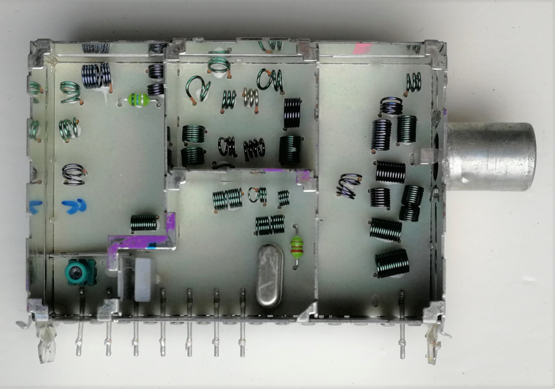
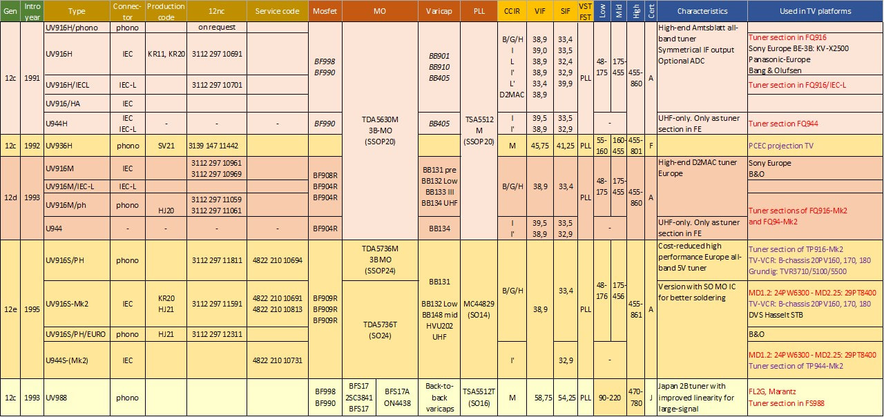
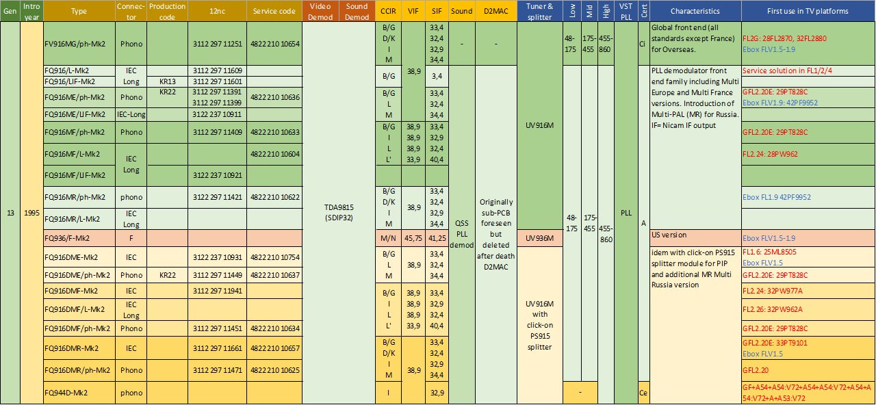
One of the remarkable steps in the UV900 concept was thus that it went back from the MO-IC to discrete mixers and oscillators, a form of de-integration rarely seen in these type of products. I think there were two main reasons why the MO-IC was dropped. The first was likely that Semiconductors, which started to have a nice business success with its still unique MO-ICs, was not willing to drop the price to the level required by BU Tuners. And secondly the Eindhoven tuner group developed a very efficient discrete 3-band tuner concept that guaranteed good performance (image rejection, input matching for VSWR and low noise, selectivity) in combination with solid Amtsblatt performance. This concept covered the entire antenna matching section, the three MOSFETs and the tuner bandpass filters, and was also used in the UV800 family. The standard European CCIR-B/G tuner UV916E was the reference model of the UV900 family, providing full hyper-band coverage with Amtsblatt performance. The UV915E was the non-PLL Amtsblatt VST version, while the UV917 was a tuned-down S-band version and the UV913 and 914 for off-air reception.
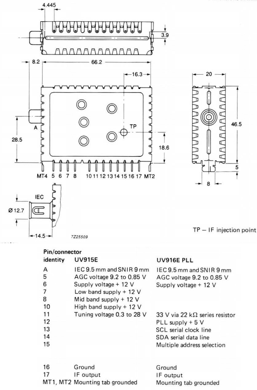
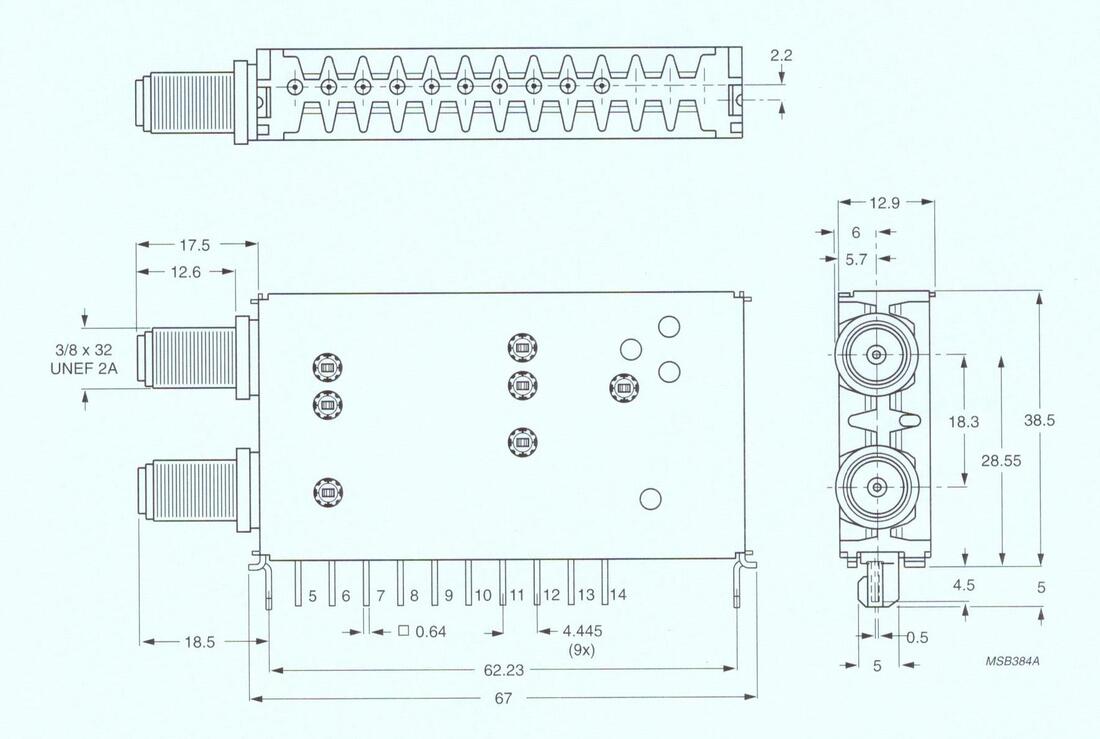
The UV900 maintained pinning backward compatibility with both the UV600 and UV800 families, although in a shorter frame. (That's why the first pin is numbered 5). When a UV900 was used as a replacement in an earlier UV600/800 chassis the long IEC connector could be used to bridge the difference in length. The consistency between VST and PLL types was maintained, a pin having the same function in both models, see the figure on the right. Pins without a function were deleted, the famous "no function - no pin" principle. So in a VST tuner pins 12-15 would be absent, in a PLL tuner pin 7-10. |
|
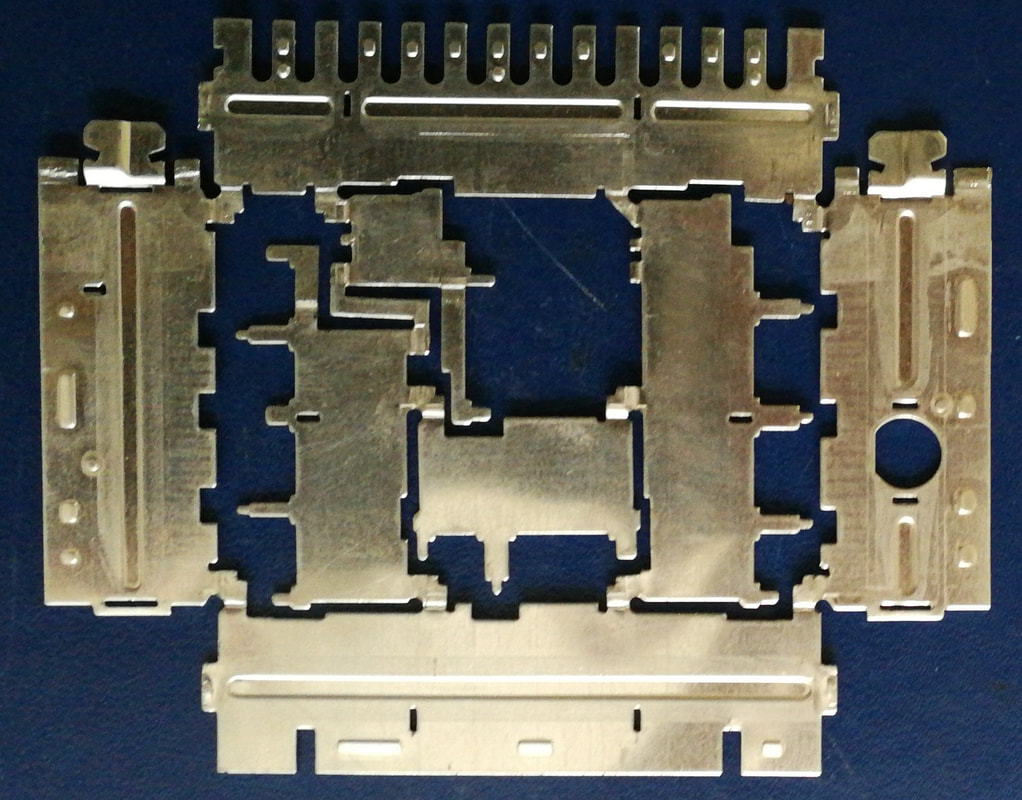
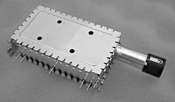
A single piece UV900 frame before being folded into shape. This is a "reverse unfolded" frame, therefore not entirely flat and some punched contours can be seen, mostly for holding the PCB. Multiple folding steps were required to assemble the complete frame. [Hugo Duran collection]
|
One of the main innovations in the UV900 was the new metal frame. The one-piece Zamac frame was definitively dropped, and replaced by 0,5mm thick tin-plated metal sheet frame. However, where metal sheet frames had been used before (ELC2000, UV400, UV700) they were always assembled from multiple pieces. The UV900 introduced the single-piece frame, which was stamped from a single sheet and then in a number of punching steps formed into the assembled frame. For most of the tuners the printed circuit board (PCB) was made from epoxy-filled glass fibre FR4, which provided the best compromise in RF performance, thermal expansion matching with the metal frame and resistance to humidity. The holes for the circuit vias were drilled and metallized-through together with the tracks on both sides, while the rectangular slots for the wire pins, frame tags and the final contour were stamped out. The different connectors, either IEC, IEC-long, phono or F, were soldered to the frame and fixed with two tags. The PCB, after SMD component placement, was clicked fix into the frame. All in all this made the mechanics a major cost reduction element of the UV900 family, and most of these elements were to be re-used in the next generations.
|
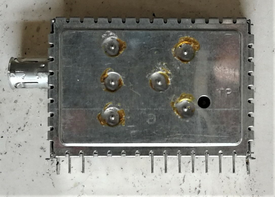
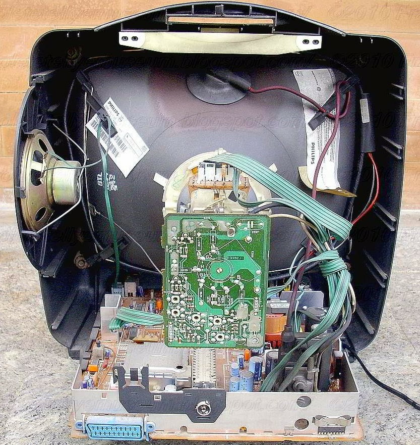
A UV915E. The cover contacts on the solder side (A-side) were soldered after alignment and final test, to avoid fretting corrosion. [Oswald Moonen collection]
|
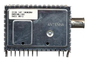
Overt time the ink jet marking was replaced by labels, here seen on a UV916E/IEC. Interestingly, as the date stamp 9413 shows this tuner was produced in Singapore/Batam during my stay there.
|
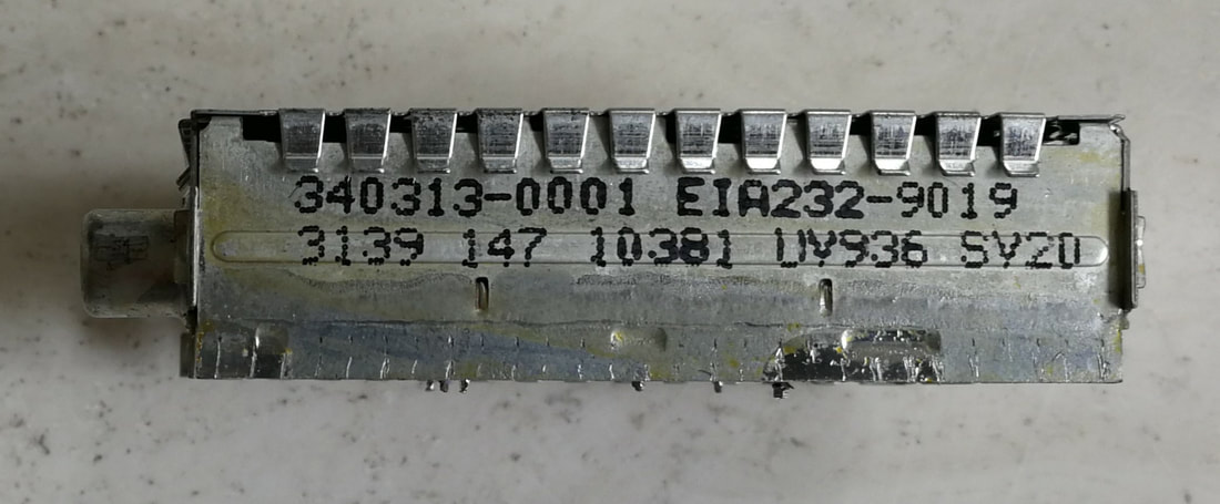
An older ink jet printer marking on an early UV936E produced in 1990 voor PCEC/Magnavox. It carries both the Philips 12nc (3139 147 10381) as well as the Magnavox code 340313-0001. [Hugo Duran collection]
|
|
Although there were in the end 22 different UV900 basic types (excluding the high-end types that will be treated separately), the general architecture can be summarized as follows:
|
The UV916E/IEC-long. The 916 was one of the main runners of the family, together with its UV915E VST counter part and the UV936E for the US market. The glass varicaps are clearly visible. The long IEC connector was used for mechanical backward compatibility with the UV800. From the point of mechanical robustness this was obviously not a very popular construction. [Oswald Moonen collection]
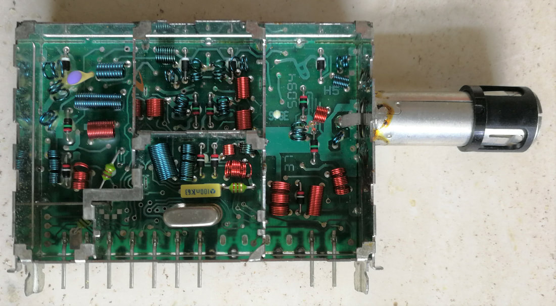
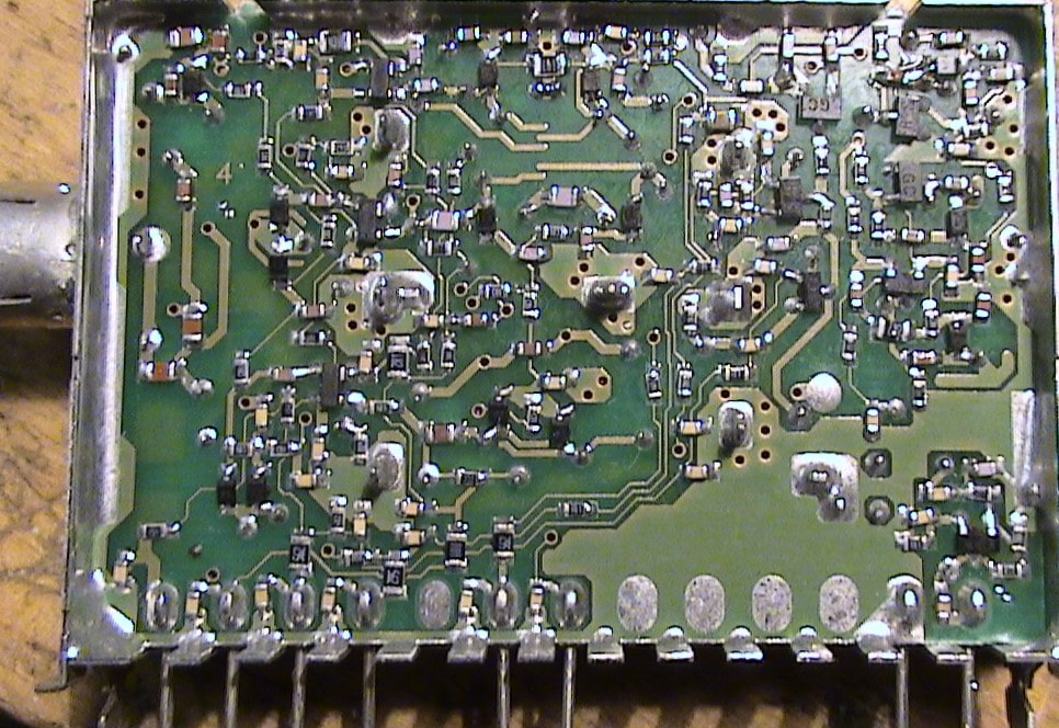
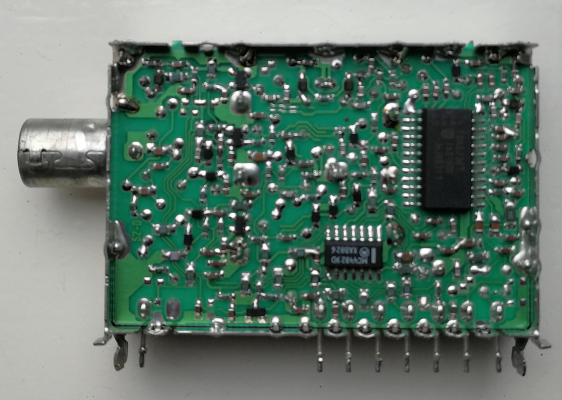
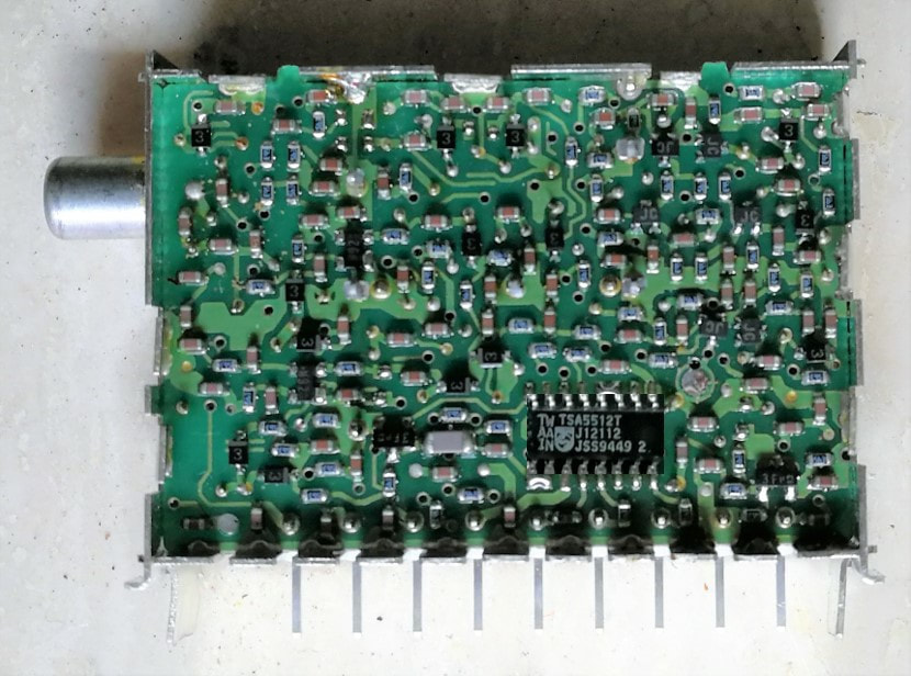
The solder side (A-side) of the same UV916E with all SMD's and the SO16 PLL IC. This is therefore a Mk2 version, no longer using the TSA5510. Most SMD's are 0603, some the larger 0805. [Oswald Moonen collection]
|
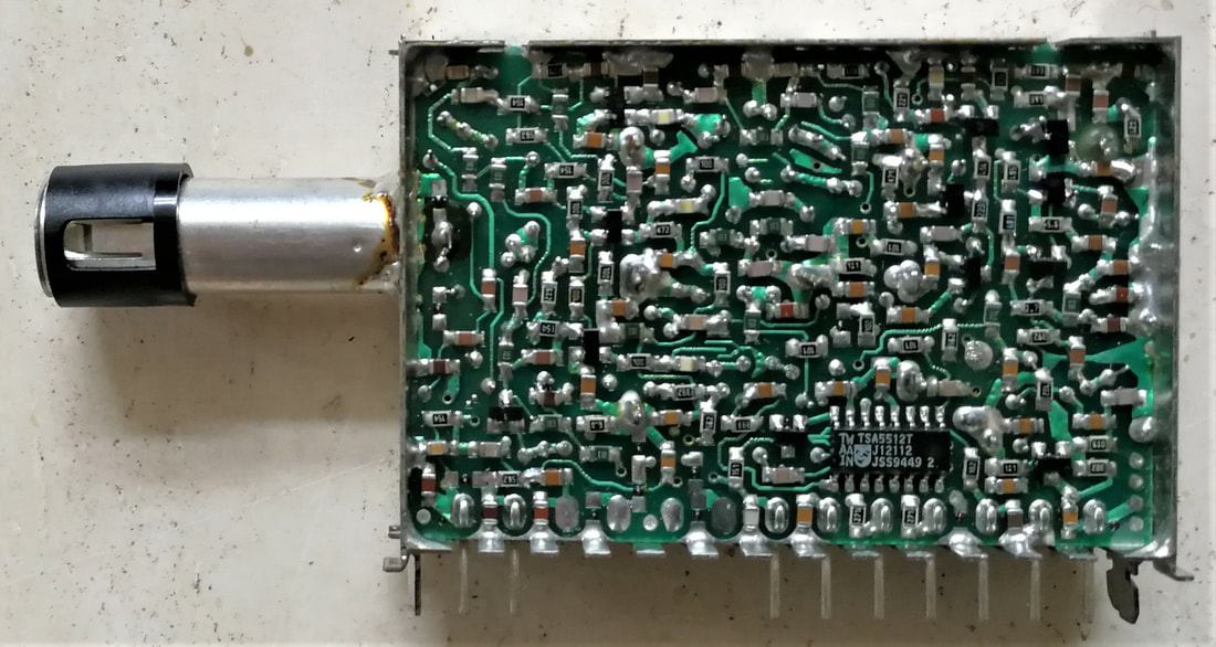
The Philips UV936E A-side. This is an early version, using the TSA5511T PLL. [Hugo Duran collection]
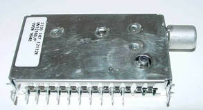
The U943-Mk1/L non-Cenelec UHF-only UK tuner. Note the smaller frame height compared to the standard UV900 models.
The UV915-MK3 from 1998, redesigned to eliminate the glass varicaps. Note the much tighter design rules and the associated less crowded lay-out. [Electroda.PL]
|
Although the UV900 tuners were conceptually all identical, there were of course some variations and specialities across the family.
|
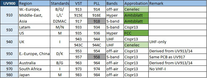
The UV900 was the largest ever tuner family made by Philips, comprising of 22 different basic models as shown in the table. 12nc-level diversity was a factor 3 higher due to connector and other options.
One of the first Philips TV groups to use the UV900 tuners was Overseas, for their 1992 GR1 global chassis. This is the small 14" screen 14GX1227, which used the UV917 VST S-band tuner. [RadioMuseum.org]
|
Interior view of the same 14GR1227, with the tuner just visible left next to the HT-transformer. [RadioMuseum.org]
|
The UV900 family was very successful, produced in very large numbers, and throughout the 1990 decade the cash cow of the BU Tuners. The first models UV917 and U943 were introduced in 1990 by the Overseas organization in their already running GR1.AX chassis, replacing the UV617 and U743. The next year the UV900 was the tuner used in the GR2 chassis, while the UV933 and 935 were used in the GR1.L Latam chassis. But the real volumes came with the use in Philips low end chassis between 1991 and 2000, the Anubis-A (1991), Anubis-S (1992/3), Anubis A5 (1995), Mid1.1 (195) and Low L6.1 (1996) with combined volumes of some 12Mio sets per year. The Philips BG-TV was extremely conservative as we've seen earlier, being very slow in introducing such innovations as I2C-bus, one-chip TV ICs and for the tuner the PLL function. As a consequence the bulk of the tuners were still VST: UV915 for the hyper-band countries (France, Belgium, Switzerland, the Scandinavian countries, Ireland), UV917 for the S-channel countries (Germany, Netherlands, Austria and southern Europe), UV913 for cheap off-air sets and the U943 for the UK. Sets for non-European countries used the UV933 (Latam), UV953 (China, Russia, Eastern Europe), UV963 (Australia and New Zealand) and UV973 (South Africa). UV916 PLL tuners were used sporadically for featured sets within the chassis, while the US PCEC Magnavox sets all used the UV936. The only real PLL chassis in this period were the Overseas G8 and G88, using the UV914, UV916, UV936, UV964 and UV974.
The Anubis low end platform was, next to regular square grey low end TVs, also used for some more exotic designs. This is the Anubis-B 21PT350. [Marcels TV Museum]
|
The UV917 in the 21PT350 as shown left. Note that the tuner is located directly next to the EHV transformer, and therefore shielded with a thick metal plate. [Marcels TV Museum]
|
Another creative design, the 14AA3324 "Book", based on the Anubis-A. Both sets shown here were produced in Monza, Italy.
|

The low end Philips chassis L6, from 1996, was the last to be based on VST tuning, using the UV913/15/17. This one, the 14PT1405, was produced in Hungary.
|
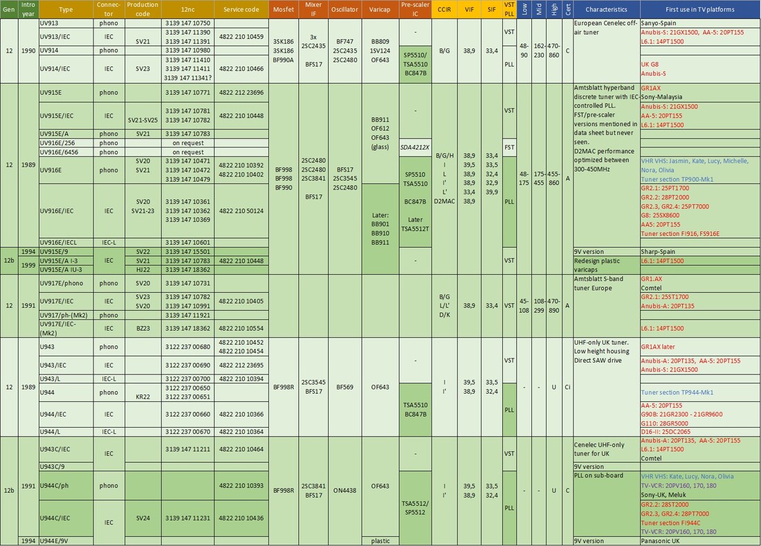
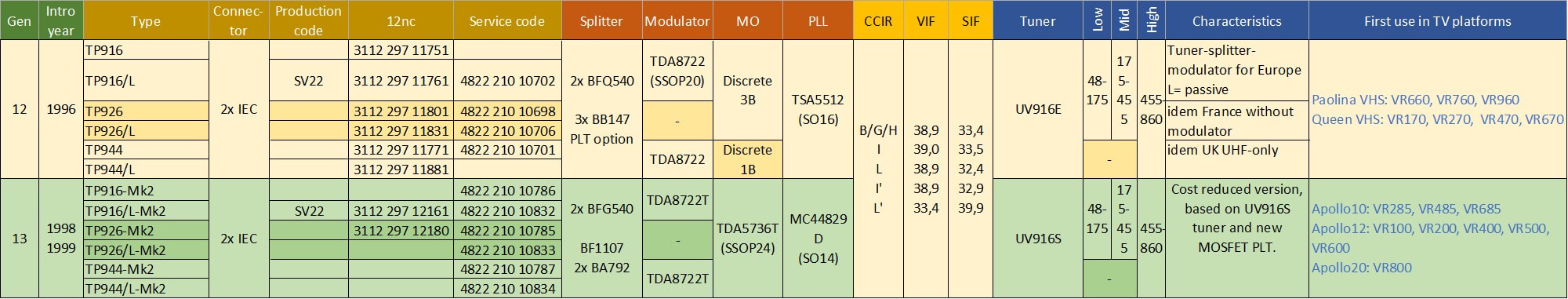
Overview of the European tuners within the Philips UV900 tuner family. Colours in the last column refer to Philipc CTV (red), Philips VCR (blue) and TV-VCR combo (purple). Black are external customers.
|
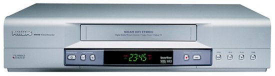
Another application of especially the UV916E was VCR. The first Philips VHS decks used the UV416 and UV616 tuners, but in 1988-89, for reasons unknown to me, a wave of Sharp and Panasonic decks was in-sourced, thus reducing the Philips tuner content to zero. With the Jasmin chassis in 1990, however, the UV916E was introduced, with the U944C for UK decks. Compared to the UV616 the UV916E must have provided an appreciable price reduction for the very cost sensitive VCR business. Up to and including the 1995 Olivia platform the UV916E was used without interruption, only the UK version migrated to the cheaper U944E.
The UV936E was the absolute main runner of the family, seeing uninterrupted use in all PCEC/Magnavox chassis in the US as well as many global low end and Overseas chassis. The last platform to introduce the UV936 was the G88 in 1995-1997, meaning 7 years of new design-ins. In that period the UV936E remained essentially unchanged, apart from the TSA5510, 5511 and 5512 upgrades. As mentioned, the main volume of the UV900 family, in fact 70%, were the VST types, although within that category there was a steady shift from off-air (UV913) and S-channel (cable, UV917) to hyper band (UV915). However, the large volumes and de facto standardization on a number of main types (UV915, UV916 and UV936) also meant a serious price erosion. The sales price of UV915 had declined from its introduction in 1990 to 1997 from 20 to 10Hfl (roughly 14 to 7USD), while the UV916E price declined from 25 to 13Hfl (17 to 9,5USD). With the UV900, tuners unavoidably started to become a commodity component, much more driven by price than performance. |
Because (low end) TV's had to be cheaper and cheaper, the tuner had to follow. Here the Monza-built Anubis-A chassis 14PT135A/00 Philetta. Note the thin plastic cabinet and the compact single PCB. [Obsolete Telly]
|
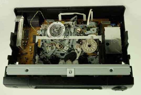
The UV916E was used in 11 successive Philips (and some Grundig) VCR platforms. Here the VR637 Michelle6 from 1993. Top left is the non-Philips splitter-modulator, a short phono connector coax cable connecting it to the tuner. [Videorama]
|
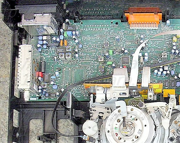
A UV900, probably a UV913 or UV917, in the 14PT135 Anubis-A chassis. Left of the tuner is a metal-covered box containing the Philips TDA4504B IF-IC. [Obsolete Telly]
|
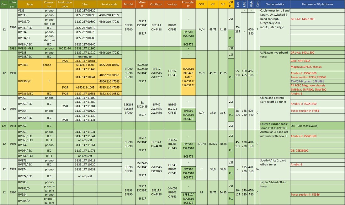
Second part of the Philips UV900 tuner family, all non-European types.
Tuner theory 10: filtering and tracking
A number of developments in the tuner applications required a much tighter control of the tuner frequency characteristics, most importantly the so-called "tilt", or flatness of the bandpass characteristic under tuning. Two mechanisms play an essential role in providing the overall tuner frequency characteristic as measured at the IF output:
- the intrinsic shape and flatness of the combined selective bandpass filters. In practice this is the multiplied characteristic of the input matching filter and the selective bandpass filter (BPF), where the aim is to have the dual-tuned BPF be the determining element, while the single-tuned input filter provides a less critical (i.e. slightly broader) constant filter characteristic.
- the tracking between the BPF central frequency and the local oscillator (LO) frequency.
|
The main difference between a tuner and a more classical receiver (radio, today especially telecom like mobile phones and WiFi) is the much larger tuning range. Especially with hyper-band the frequency ratio of low and mid band is typically 3,5 (from 48 to 170MHz) and 2,6 (175 to 450MHz). The challenge is to keep the BPF characteristic constant while tuning over such a large frequency range. For tuning a frequency ratio of 3,5 a varicap with a ratio of 3,5^2=11,5 is required, but this roughly 10-fold variation in C gives a sqrt(10)=3,3 in variation of the Quality factor Q. The illustration on the right shows that for a constant ideal filter characteristic the product kQ should be 1 or slightly higher. As we will see 1-1,2 is the ideal value. How to achieve this?
|
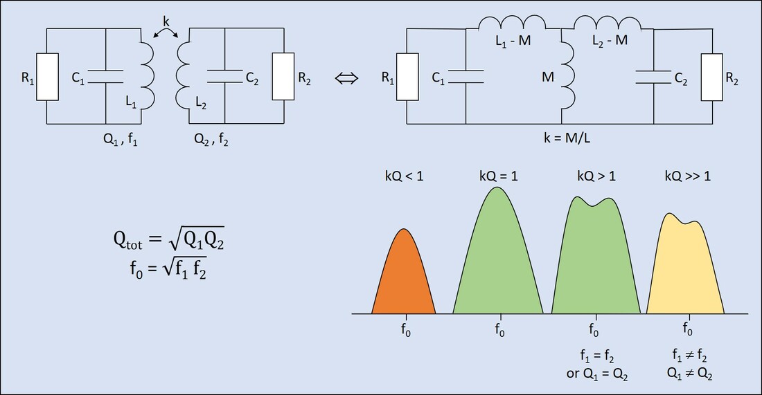
Bandpass characteristic of a dual-tuned BPF, as a function of the coupling factor k.
|
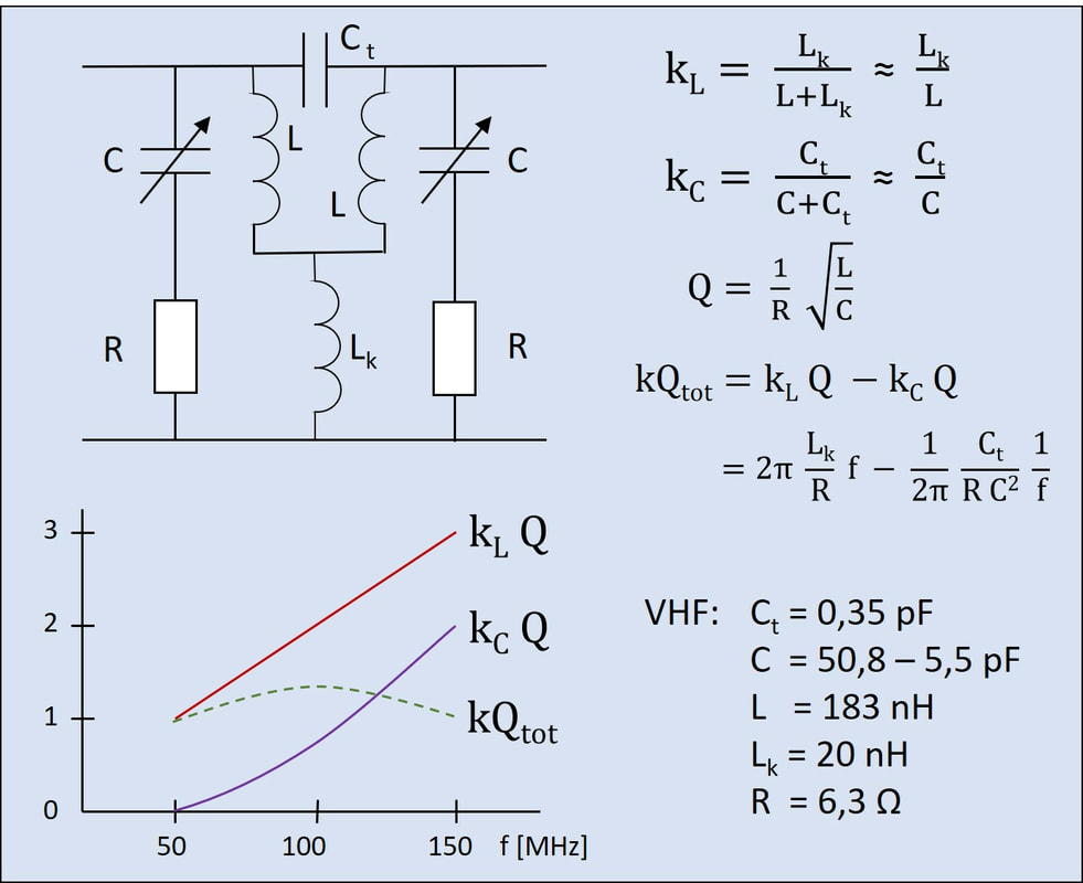
The practical implementation of a double-tuned BPF for 2 octave tuning. At the bottom an example is given for a combined VHF-I and III BPF, using typical values for a such a design.
|
Compared to the theoretical BPF from the first figure, a more practical BPF is designed as shown on the left. The capacitance C is now variable, and effectively the varicap variance. R is the parasitic series resistance of the varicap. Two elements have been added to "shape" the characteristic under tuning: a foot inductor Lk and a top capacitor Ct. With the foot inductor the mutual coupling between the two main BPF inductors can be accurately set, as per the diagram upper right. This ensures a constant k over frequency, independent of magnetic coupling. However, as can be seen in the left figure, kLQ increases linearly with the frequency and on its own would give a rapidly degrading BPF characteristic with kQ>>1. Therefore the top capacitor is introduced, which, for increasing frequency, essentially starts to bridge the BPF. As the formula shows, the net kQtot (green dotted line) is the difference between the inductive kQ (red line) and the capacitive kQ (purple line). As the formula also shows Lk and Ct can be individually tuned to engineer the kQtot to maximum flatness across the band. First Lk is set such the kLQ at the low end of the band is 1, then Ct is tuned to achieve the same at the upper end of the band. Ideally kQtot then varies between 1 and 1,2 across the whole band under tuning, thus providing a stable BPF characteristic.
|
Assuming the BPF had the right characteristic (kQ) over the entire tuning range, the next challenge is local oscillator tracking. Only if the LO frequency is exactly the intermediate frequency (IF) higher than the centre of the BPF will the properly filtered input signal be mixed down to the IF. In case the LO is not correct, say 5MHz too low, the input signal 5MHz below the BPF centre frequency will appear at the output of the IF filter. At this frequency the transfer characteristic of the BPF is obviously much lower in amplitude and rotated in phase, leading to serious signal distortion.
|
To make an oscillator be exactly the IF higher than the input frequency over roughly 2 octaves is the real challenge of tuner design. To achieve this the BPF and oscillator tank circuit, although conceptually identical parallel tuned circuits, must be adapted and adjustable. The figure on the right shows the basic main inductor Lp and varicap Cvar in parallel for both, but now each with two added elements: a padding capacitor Cpad and a parallel capacitor Cpar. Understanding the concept is easier using a numerical examples, in this case again for a low band tuning from 50 to 170MHz.
For the BPF the Cpad is so much larger than the varicap capacitance that effectively it plays no role. So in a first step Lp is adjusted to 165nF such that at the lowest tuning voltage (Cvar = 60pF) the filter centre is at 50MHz. But without the Cpar the upper tuning edge would now be 219MHz (165nF // 3,2pF). With Cpar the upper band edge can now be tuned to the targeted 170MHz (blue line), essentially by reducing the integral capacitor variance from 60 to 3,2pF to 60 to (3,2//2,1)=5,3pF. Any deviations due to e.g. parasitics can be tuned out with Lf. The oscillator is now more complex. The varicap only (red line) gives an LO tuning from 68 to 294MHz. The padding capacitor is first used to fix the low edge of the band to slightly above the target 50+38,9=89MHz (the orange line). With the parallel capacitor the tuning curve can now again be rotated to the correct upper band edge of 209MHz (green line). It can be verified that the two tuning curves are now exactly 39MHz apart for all varicap capacitances. |
Explanation of the tuning alignment of the BPF centre frequency (left) and local oscillator (right). By adjusting the inductor Lp first and then the capacitances the proper tuning curves can be obtained. Numerical values for a low band example. For simplicity all curves are drawn as straight lines, in practice they can be slightly curved, depending upon the varactor C(V) curve shape.
|
An illustration of the tuner tracking mechanism. These are simulations on the UV936 NTSC tuner, using the circuits on the left including detailed parasitics (not shown). With the varicap capacitance changing from 13 to 2pF the entire UHF range is covered with a constant IF of 45,75MHz (with a 1MHz error). Note the non-linear relation between Cvar and the filter centre frequency and thus the tuning voltage. The centre graphs show the nominal filter and tank characteristics. However, outside their target band they both feature resonances in the 30-400MHz domain, shown upper right for the BPF. Especially strong unwanted signals at the positive spurious resonance can result in so-called breakthroughs. [Philips Tuner Development Report "Theoretical Model for UHF tuner circuit", Hans Brekelmans, February 1993 via Martin Barnasconi]
The explanation above is based on a single filter section. In practice alignment is much more complex due to the dual-tuner BPF, parasitics that will make the curves less ideal (especially at increasing frequencies towards UHF), unwanted magnetic coupling between inductor coils, and the possible influence of the parallel bands that are not in use but nevertheless can passively load the active band. And then there is always the need to align and tune for other parameters like image rejection. For the latter a very small "vane" capacitor is put across the entire BPF and tuned for a attenuation maximum at the LO frequency (2x38,9=77,8MHz above the BPF centre, especially for N+9 in UHF. This then also gives additional N+5 suppression required for Cenelec. Another issue in the above analysis is the assumption and prerequisite that the varicap values under tuning in both the BPF (with at least 2 varicaps!) and the LO are exactly identical. A serious challenge!
These analyses and examples are all taken from the "Accumulated Tuner Knowledge" book that was written within the BU Tuners Development organisation, containing much more detailed and extensive analysis of these type of tuner characteristics.
These analyses and examples are all taken from the "Accumulated Tuner Knowledge" book that was written within the BU Tuners Development organisation, containing much more detailed and extensive analysis of these type of tuner characteristics.
Varicap developments, 1980-2000
Although much of the focus of the tuner key components increasingly goes to ICs, the MOSFET and varicaps should not be forgotten. They also showed consistent innovation at this component level. Let's start with the varicap, also based on the previous analysis on tracking. Since the introduction of the BB105 varicap in 1968, 3 more generations were introduced until 1990. In that period varicaps had been optimised per band (VHF-I, -III and UHF) where especially in view of first the S-channels and then hyper-band the tuning ranges were seriously stretched. It also meant the full voltage range for the capacitive tuning of the varicap was needed, so from 0,5 to 28V. The latest varicaps (the BB130 family) had a lowest capacitance of 2-2,5pF at 28V. The differences were in the range, where VHF required the largest range. The BB132 for VHF-I thus had a maximum capacitance of up to 75pF, and a capacitive range (C(0,5)/C(28) of 25-30. Because the filter frequency changes with the square root of C that gives a theoretical range of 5-5,5 in frequency. As we've seen in the previous chapter this reduces to a factor 3,5 after alignment, the margin is needed to guarantee tuner alignment in all practical cases of component tolerances and value spreading. UHF diodes like the BB134 didn't require such high ratios (typically 8,5-12) but focused on low parasitics and especially series resistance.
|
To achieve these wider tuning ranges quite some process engineering was required. Multiple implantation steps with different doping materials and levels were made to arrive at the overall doping profile that provided the requested C(V)-curve. One of the main requirements of the C(V) curve is to avoid unwanted filter de-tuning in case of large input signals. Because the C(V) curve is non-linear, large input signals could give an asymmetrical output signal with a "DC capacitive component" delta-C, see the figure on the right. It can be shown that in order to make Delta-C zero the C(V) curve needs to have a third order shape, which can be achieved through proper optimization of the varicap doping profile. In production the Philips varicaps were therefore characterized at 9 different voltages to guarantee the C(V) curve had the proper shape.
The last step in varicap optimization is then the device-to-device matching. As the previous section has shown, in the ideal case the two varicaps in the BPF and in the LO tank circuit (and to a lesser extent the pre-filter varicap) should all have exactly identical C(V) curves for proper LO and filter tracking. The target for this matching was defined as <0,5%, a major challenge. There was one relaxing factor though: the matching is required only for the four varicaps in one tuner, between sets of varicaps for different tuners the spread can be roughly 1.5%. |
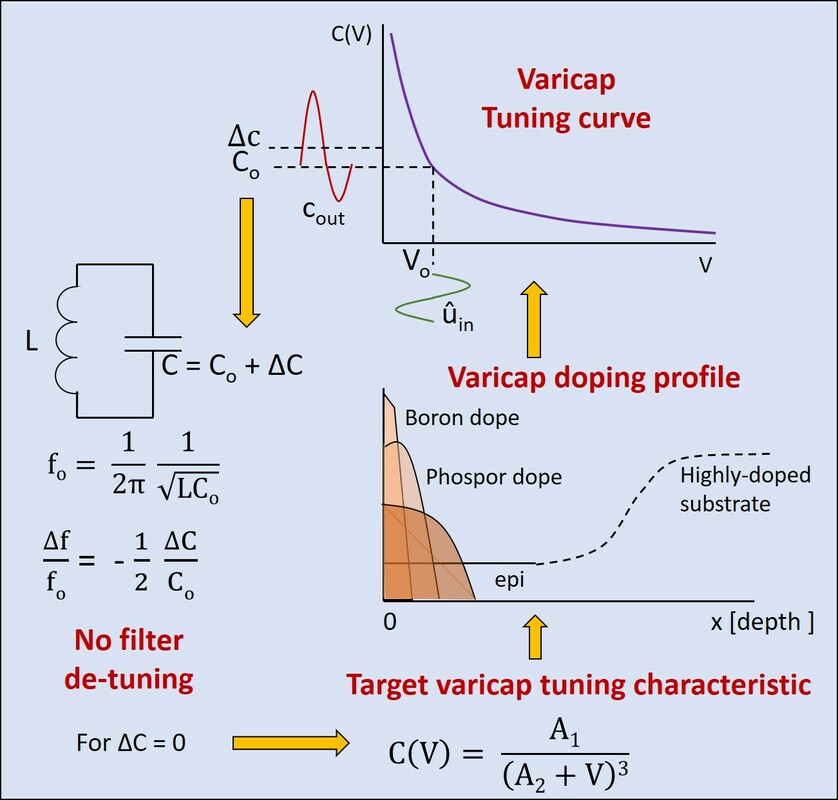
Figure explaning the relation between varactor characteristic C(V), its possible effect on filter de-tuning in case of large input signals, and how this can be avoided by having the proper 3rd-order curve that can be realized through proper doping profile engineering of the varicap.
|
The small plastic leaded packages of the BB130-40 and BB170-80 varicap families. [Philips Semiconductors Data Sheets]
|
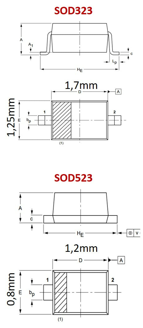
Matching levels that were achievable through optimal on-wafer uniformity process control were in the order of 2,5-3% across all devices on a wafer. Around 1980 the BB809 and BB909 were the first varicaps delivered with such guaranteed matching. Obtaining sets of <0,5% matched diodes required additional selection, which was done using the Direct Measurement Assembly (DMA) method. In this case all diodes on a wafer were individually characterised at three voltages (0,5, 10, 13,5 and 28V), and then individually selected to form closely matched series when put in the reel. In the first generation DMA diodes (BB132-134) four consecutive diodes had a guaranteed match of <1,0% in VHF (BB132), <0,7% in VHF-III (BB133) and <0,5% in UHF (BB134). This matching was maintained in groups of at least 50 diodes, and per reel there were less than 15 different groups. This generation varicaps also introduced the 1,7x1,3mm-size SOD323 miniature plastic package.
The very tight matching requirements of the BB132-134 family was driven by the need for very low tilt D2MAC and digital tuners, especially the UV916M. However, with increasing price pressure for the regular tuners the focus shifted from extreme matching to lower cost and footprint. The BB145-146 set was an intermediate step, pushing for extreme tuning range for the switched 2-band tuner, the BB147-152 was the regular family for the UV1300 family. At the same time matching requirements were reduced to <2% mismatch over 15 devices. The BB178-182 family was the next generation, introducing the 1,2x0,8mm SOD523 plastic package. In the meantime, like for most key components, a dual sourcing policy had established Hitachi as the other varicap supplier, where the two companies (Philips Semiconductors and Hitachi) were forced to offer exact copies of each others devices. So when Hitachi introduced the improved HVU202A, 300A and 363A Semiconductors was forced to release the BB149, 152 and 153. This dual sourcing in turn gave a big price pressure on the components, and in the end a varicap, despite its advanced engineering and matching, cost an average 2,5$ct. With this the varicap had essentially reached the end of its development. There was no need to improve it further, given the good matching and tuning curves, and there were no opportunities for real cost breakthroughs. The last step that happened was the move to an even smaller SOD523 package, but the varicap dies remained the same. And so the BB178, BB179 and BB182 were effectively the last tuner varicaps developed by Philips. They would therefore become the standard components for all successive tuner generations, including the frontends and digital tuners. As late as 2008 they were still the components of choice in new tuners. |
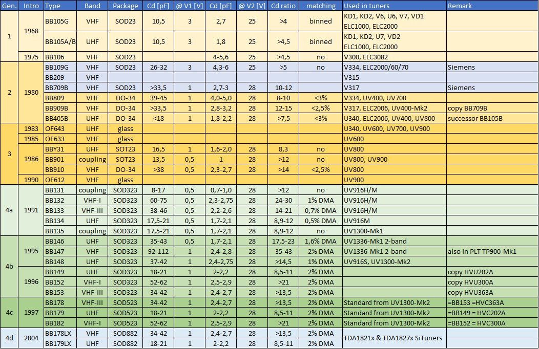
Overview of the different generations tuner varicaps produced by Philips Semiconductors. Note that the BB178-179-182 family was the last one developed specifically for tuners. They were used without interruption for all Philips tuner families until 2010!
New MOSFETs, 1985-2000
The MOSFET remained the critical input device, the first active element after the passive antenna matching filter. The primary role is still that of low noise pre-amplifier, while secondly it provides the RF Automatic Gain Control (AGC). Like that of the varicap, the basic concept of the MOSFET never changed: it was a dual gate MOSFET tetrode, with mostly two identical FETs stacked in a cascode configuration. Because MOS transistors are extremely sensitive to Electro-Static Discharge (ESD) each gate is protected by two anti-series diodes to substrate that will conduct in case of high surges on a gate. The first rounds of innovation in MOSFETs were purely technology based: in the slipstream of the rapidly improving IC-technologies and the associated production technologies, also MOSFETs were manufactured using increasingly more advanced process technology. Where the initial devices still used around 5um gate length technology, with the 3rd, 4th and 5th generation this reduced to roughly 1,2um (BF998), 0,9um (BF904) and 0,5um (BF1101).
|
Another technology breakthrough was the introduction of enhancement mode FETs. The first three generations MOSFETs were depletion mode, meaning that the gate-source voltage of a FET was negative, especially during AGC gain reduction. This always required complex biasing schemes. With an enhancement mode lower FET the Ug1s is always positive, making biasing much more convenient. This was introduced with the BF998, which also introduced the all-band MOSFET. It was immediately applied in the UV800 and UV900, where it was used for ten years in massive numbers.
The higher current densities and lower parasitics associated with the smaller scale technologies could be used to optimize performance. Initially this was focused on getting more gain (transconductance) until that reached 40mS at 8V Uds. However, it turned out that with 40mS the gain had become too high, leading to higher cross-modulation distortion. So the transconductance finally settled on 30mS at 5V supply, while the technology margin was then used to improve the noise figure, which over the generations reduced from 2,8dB to 1,0-1,1dB at 800MHz. |
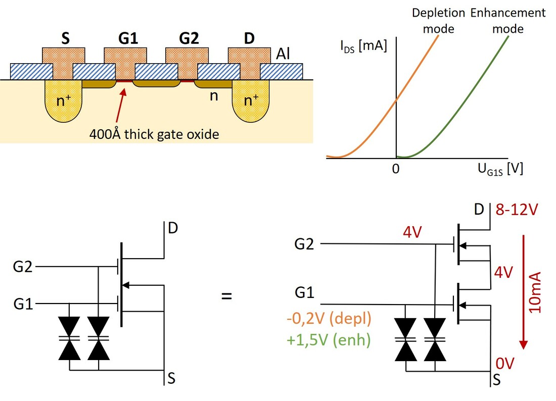
Concept of the 3rd generation dual-gate RF MOSFET family BF990-BF998. Typical voltages are given for the nominal condition of maximum gain for depletion type (orange) and enhancement type (green) lower MOSFET.
|
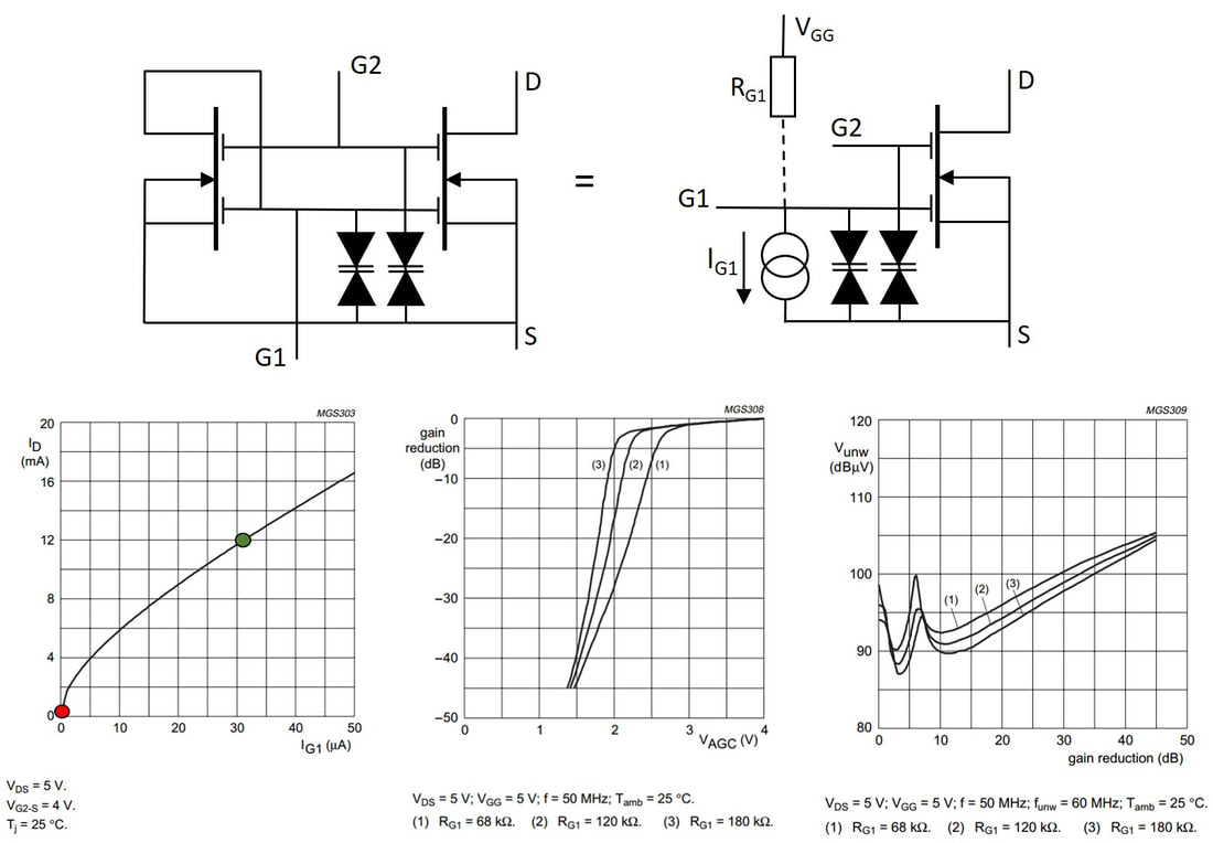
The new internal current mirror MOSFET bias scheme for improved x-modulation performance. The graphs are for the much used BF1101. The left graph shows the on (green) and off (red) operating points under band switching. [Philips Semiconductors BF1101 data sheet]
|
The next innovation was the introduction of an internal current mirror inside the MOSFET package. This current mirror was a scaled version of the main dual gate MOSFET, but operating at a substantially lower drain current of 30-50uA. Because the current mirror drain was connected to G1, this became also the G1 current. External bias resistor Rg1 set the current mirror bias; for typical settings see the figure left. The main purpose of the internal biasing is to maintain optimal cross-modulation performance under gain control. Again, Rg1 and the mirror current can be used to vary the actual performance, but the figure shows that for typical 120kOhm Rg1 the cross-modulation is better than 90dBuV for the interferer, and improving for increasing gain reduction. The small peak at about 7dB gain reduction is due to a resonance between the Miller capacity Cgd and the gm of the first FET.
The functionality of the MOSFET had now stabilized to a 5V 12mA setting, resulting in 30mS transconductance (and thus a voltage gain of 0,03RL), band switching using Vgg coming from the open collector band switch drivers within the PLL IC, and finally more than 40dB gain control range by reducing Vg2 from the nominal 4V to 1,5V. And all that for around 4$ct! |
A last step was the introduction of twin MOSFETs for VHF, with two devices plus biasing on a single die. The SOT363, although now 6-pin, kept the same external dimensions as the previous 4-pin SOT343. Overall this gave a significant 30% materials and assembly saving.
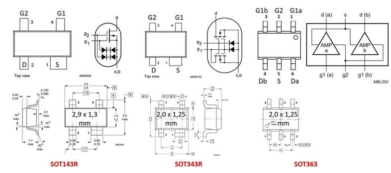
Overview of the MOSFET packages in the period 1985-2000. [Philips Semiconductor BF998, BF1101 and BF1204 Data Sheets.]
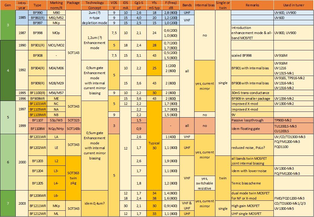
Overview of the Philips Semiconductors tuner dual-gate MOSFET families and types. Most types are used as single band variable gain amplifiers. The BF1107 and 1108 are passive loop-through switching MOSFETs. The SOT363 types are dual MOSFETs, combining two bands.
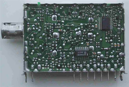
UV900 high-end tuners, 1991-1995
Towards 1990 the Tuner business had a dilemma. The UV816 of the existing family was maybe the best tuner in the world, but much too large and too expensive. The new UV900 family described above had only one objective: cost reduction, and in order to achieve that had dropped the mixer-oscillator (MO) IC and returned to discrete implementations, accepting some performance degradation compared to the UV816. However, a number of high-end customers remained, essentially demanding high performance for UV900 compatible prices. Especially Sony-Europe, out of its Pencoed (South Wales, UK) design centre and factory, had been using Philips tuners for many years, mostly in its top line Trinitron chassis: the UV417, UV616 and UV816. The UV916H (H for high performance) was defined to fulfil this requirement, and was, at least initially, the only MO-IC tuner within the UV900 family.
|
Conceptually the UV916H was predominantly a migration of the UV816 concept, using the TDA5330 MO-IC, to the smaller 900 housing. The use of a MO-IC in principle improved cross-modulation, LO-pulling and LO-feed-through due to higher isolation. The main innovation in the UV916H was the new TDA5630 3-band MO-IC, which, compared to the TDA5330 of the UV816, had the supply voltage reduced from 12 to 9V. This supply voltage reduction, however, had serious design repercussions and resulted in linearity problems, which took multiple re-designs by the Semiconductors team to solve. At the same time the TDA5630 also showed some considerable improvements, due to the use of simplified 2-pin (and for UHF 3-pin) oscillators. The IC no longer required an external IF filter between the mixer input and SAW driver output, saving 4 pins, although this required more subtle output matching of the IF.
Other than that the UV916H used the same MOSFETs (BF998 and BF990) and varicaps as the mainstream UV900 tuners. But due to the MO-IC the performance showed a number of improvements:
|
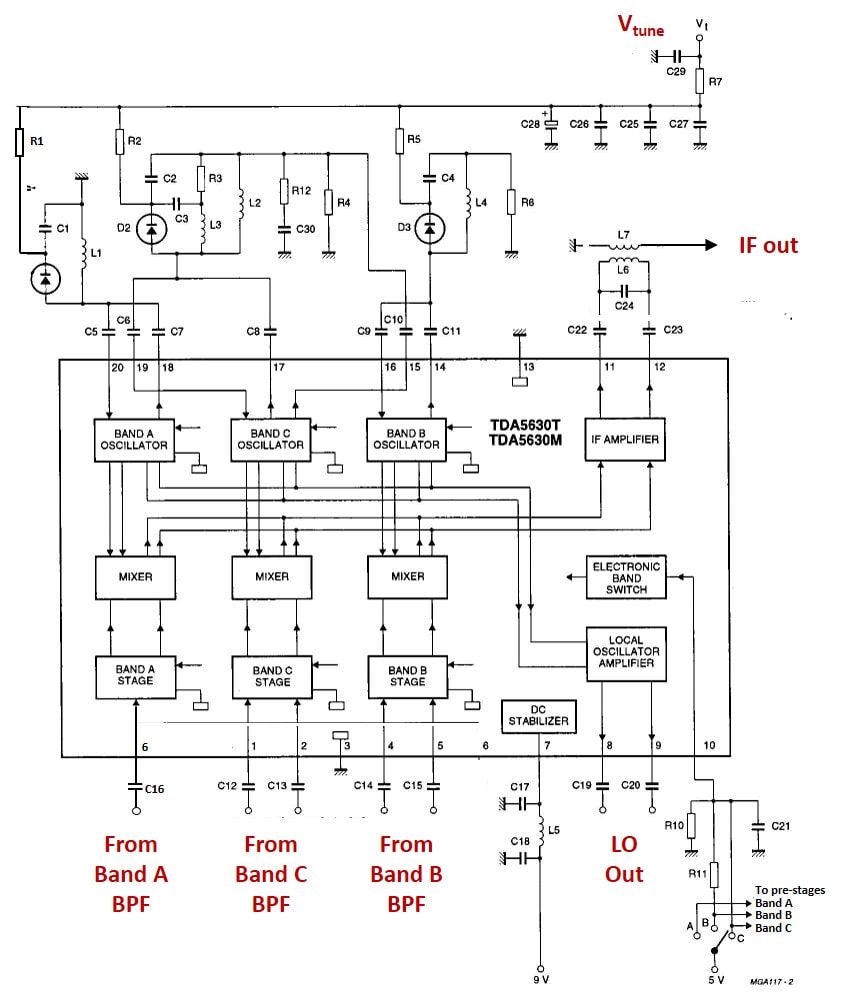
Block diagram and application of the TDA5630 9V MO-IC that was introduced in the UV916H. [Philips Semiconductors TDA5630 Data Sheet]
|
Top side view of the UV916H/IECL, with the long IEC connector for footprint backward compatibility with the UV816. [Pieter Hooijmans collection]
|
Bottom side view of the Philips UV916H/IECL. Both IC's use SSOP20 small-pitch packages, which were at he limit what could be wave soldered. [Pieter Hooijmans collection]
|
|
The original target of the UV916H was to outperform the UV816, but this turned out to be a real challenge. The UV916H was clearly the highest performing UV900 model, but achieving performance above the 816 effectively was impossible, where the lower supply voltage was the main reason, although the smaller size also made life more difficult. In the struggle to improve performance the UV916H saw some upgrades (H2, H3), mostly using newly released varicaps or MOSFETs. In parallel discussions had started about performance improvements that were related to a number of application developments. The most urgent was "Super flat response", or low tilt, for the following applications:
|
Tuner theory 11: tilt
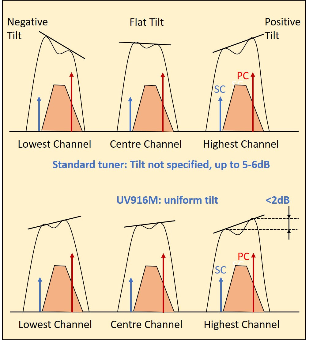
Tilt is defined as the difference in transfer characteristic of a tuner channel (overall, from RF in to IF out) at the picture carrier and sound carrier. It is measured in dB, and is an indication of the flatness of the characteristic. As we've seen in Tuner Theory 10 the typical transfer characteristic is of a dual-tuned BPF with kQ<1,2, but only in case of total symmetry between the two BPF sections the characteristic can be flat. Furthermore the overall characteristic is the multiplicative result of input filter, BPF, amplifier and mixer frequency characteristics and finally the IF filter.
In standard tuners the tilt can be either positive (PC higher) or negative, and typically varies 5-6dB when tuning from the lowest to the highest channel in a band, see the top figure. The UV916M in contrast targeted consistent positive tilt of less than 2dB, see the lower figure. |
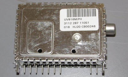
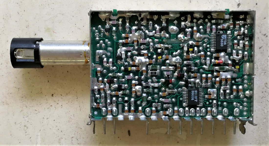
A Philips UV916M/phono. The label shows it is produced in Kwidzyn, Poland (HJ) in 2000 week 16 (016). [Internet]
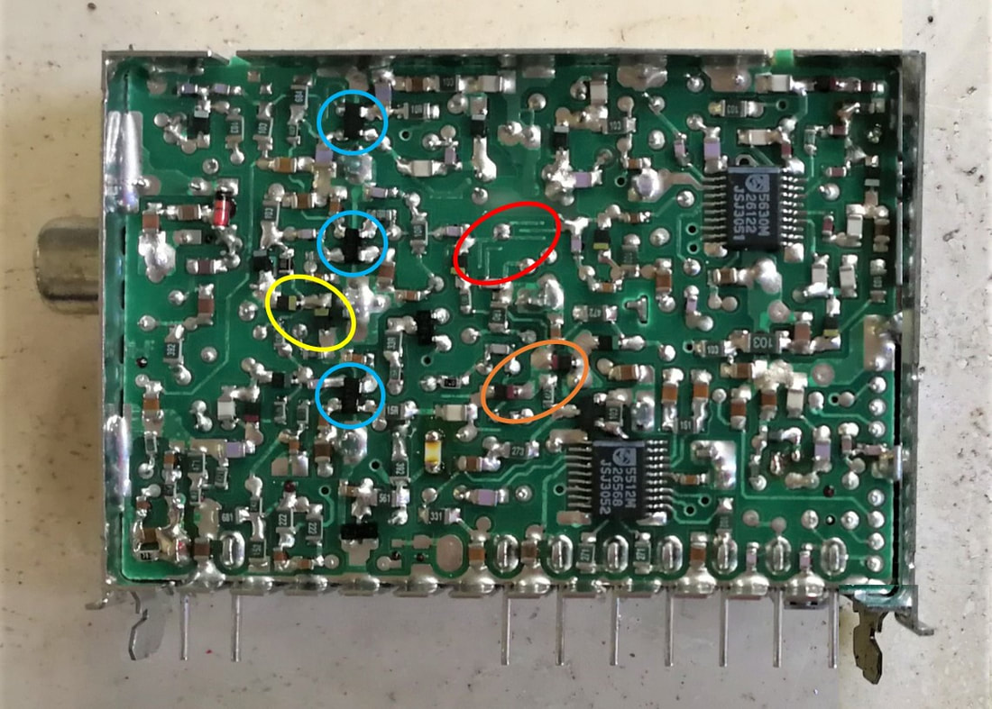
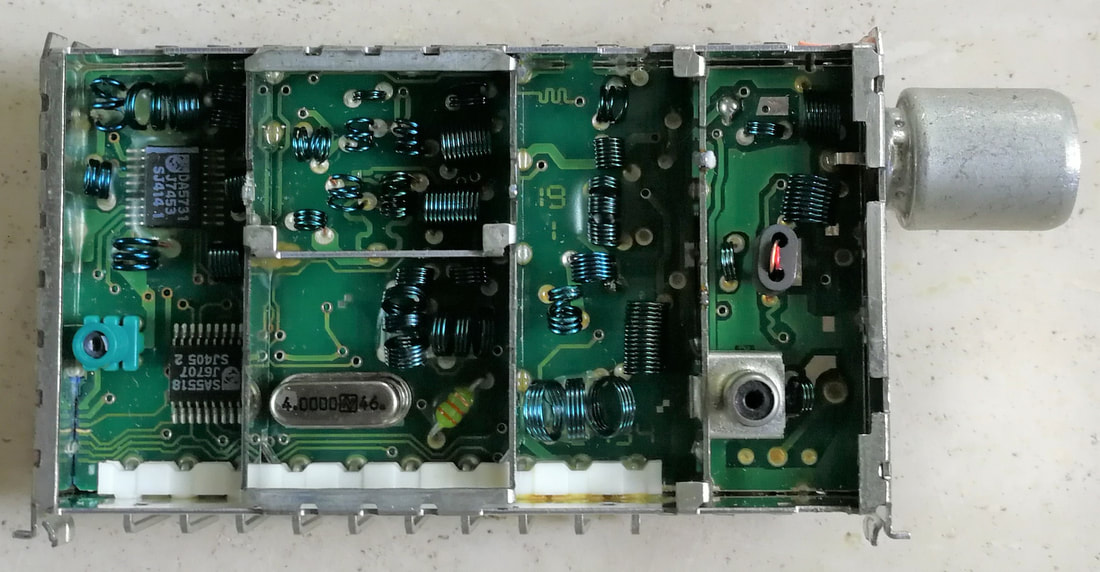
The SMD-side of the UV916M tuner. In the orange circles the low band back-to-back varicaps; yellow idem for mid-band; blue are the three MOSFETs; red the mid band printed top capacitor of the BPF. In the lower right corner the 7 interconnect contacts to the IF are visible, when the tuner is used as part of the FQ900-Mk2 front end. [Pieter Hooijmans collection]
Both the UV916H and UV916M were very good tuners, fulfilling the most stringent requirements for any analogue television application. However, the market for high end television was small compared to the total TV market: roughly 10% of the market in Europe, 0% in the US and less than 5% in the rest of the world. Only a few TV set makers therefore used these tuners, including the main high-end competitors of Philips BGTV: Sony Europe, Panasonic Europe and Bang & Olufsen. Philips at this time did not use stand-alone tuners in its high end sets but tuner-IF front ends. The first generation FQ900 used the UV916H as tuner, the FQ900-Mk2 the UV916M. However, combined volumes of the UV916H, M and their frontend versions never exceeded some 350k units per year.
|
The UV916M featured a number of design optimizations compared to the UV916H to meet all these requirements:
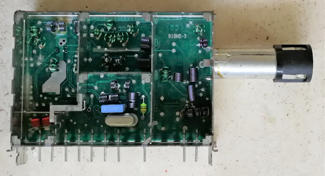
SMD bottom side of the UV916S-Mk1. Note the pinning differences between the SSOP24 MO-IC and the Motorola SO14 PLL. [Internet]
|
Top view of the UV916S-Mk2. Because of the single-sided PCB there are neither tracks nor soldering on this side of the board. [Jac Janssen collection]
|
The component side of the UV916S-Mk2, identical to the Mk1 but with an SO24 MO-IC instead of the SSOP24. [Jac Janssen collection]
|
|
A last tuner in this family of high performance tuners within the UV900 family, and in fact the last 900-tuner to be designed, was the UV916S (with the S probably for Saving). It was intended as a cost-reduced successor of the UV916E, used so far in the Standard Dreux chassis GR2.2 and GR2.4, and intended to be introduced in the new Mid1 and Mid2 chassis. Compared to the UV916M, from which it was derived, there were a number of changes in the UV916S:
|
Pictures of the UV916S in sets are rare. Here the 28PW6302/02, a Mid1.2E chassis Black Line S TV. [Obsolete Telly]
The Mid1.2E chassis introduced 16:9 screen sizes in the mid end domain and used the new UV916S. This is the 24PW6322 from 1998. [Philips]
|
The second generation TV-VCR combi, the 1996-97 Beta chassis, was the first to use the UV916S. This is the 14PV162.
|
The third generation TV-VCR was the Mono98 chassis, again using the UV916S and UV1216D. [RadioMuseum.org]
|
Overview of the Philips UV900 high performance tuners with MO-IC (except for the UV988).
FS900 and FQ900 TV Front ends, 1991-1993
Terrestrial front ends, that is a tuner plus IF, remained one of the most frustrating product segments for the BU Tuners in its relation with the big Business Group TV. The FQ800 family was being used for all Brugge high-end FL1 and FL2 chassis, but volumes were modest at 220k modules/year. Furthermore diversity was an issue, with one single type accounting for 70% of the volume, two types for another 20% and the next three for 10%. So when discussions about the next generation 900 front ends started the BU objective was to reduce diversity by focussing on a few multi-standard versions. Unfortunately the BGTV organization politics and structure decided differently.
|
The first to ask for new front ends was the Overseas organization for its 1993 G8 chassis. They required front ends, but less expensive than the FQ800, and three types were defined: the FS916 for B/G, the FS936 for M/N in the US and Latam, the FS986 for Japanese M. The concept of the FS900 was much more basic than the FQ800:
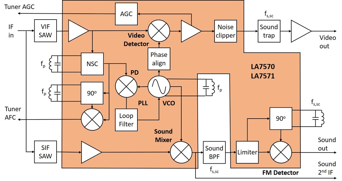
Block diagram of the FS900 IF section around the Sanyo LA7570 IC. The single PLL-controlled VCO is used for the synchronous detection of video (top flow) and sound (bottom flow).
The Sanyo IC had one drawback: it required a separate Sound IF SAW filter. However, this allowed the same VCO to be used for identical synchronous detection of both the video and quasi-synchronous sound, which minimized video-sound crosstalk. The dual SAW filters plus the price of the IF-IC made the FS900 relatively expensive for its functionality. As a consequence (probably) the Overseas organization decided to use standard UV900 tuners for all European models of the G8 chassis, using the FS936 only in Latin America, Taiwan and Korea, and a handful of FS986 in Japan in Marantz sets.
|
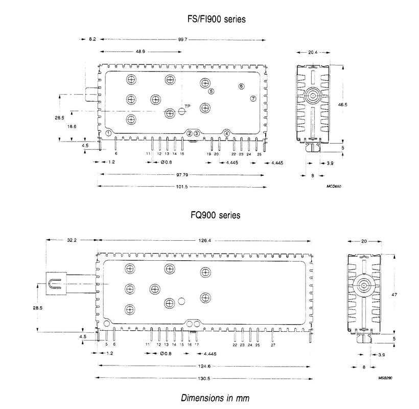
Mechanics of the short FS900 front end (top), with a 100mm long body, and the 125m long FQ900 front end (bottom).
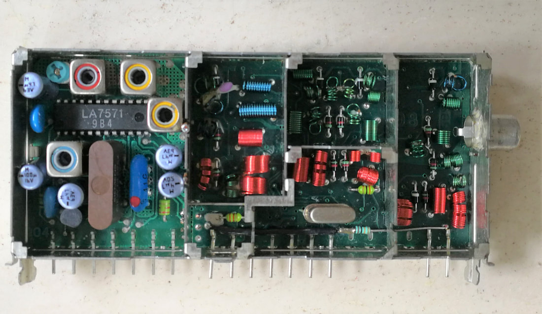
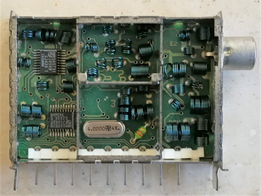
Top view of the FS936E. The different filters and components can easily be compared with the block diagram left. [Hugo Duran collection]
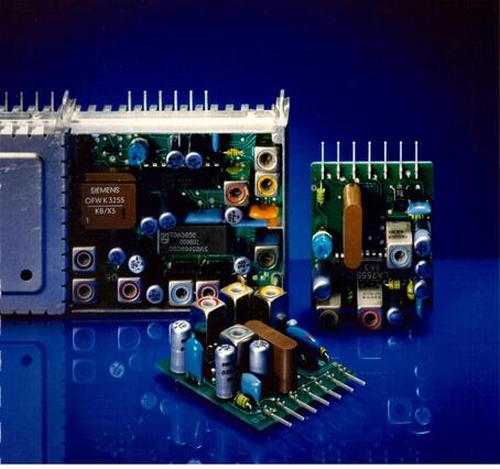
Publicity picture showing the IF sections or PCB of the FQ816 (upper left), FS936 (centre) and FI916 (front). [Johan Bos]
|
The Eindhoven High-End Lab, together with the Brugge TV development, however, had higher specifications for their targeted front ends, which were to be introduced in the already running Feature Line FL1 and FL2 chassis that were using the FQ800. The FQ900, as it was called, was expected to be a major cost reduction from the expensive FQ800, without any performance compromise but with the addition of some new features. Compared to the FS900 this meant:
- use of the high performance UV916H tuner (which was in fact developed specifically for this application);
- multi-standard solutions for the complex European border zones. The same Multi-Europe (ME; covering B/G as main and L and M as secondary standards) and Multi-France (MF; L/L' as main and I and B/G as secondary). In other words, the same multis as for the FQ800;
- multi-standard video demodulation using the TDA9802;
- stereo FM sound demodulation to be included using the TDA9820 dual FM demodulator;
- mono AM sound demodulation using the TDA9830 for SECAM L/L';
- IF output optionally available for external D2MAC demodulation. For these cases a separate D2MAC IF-module was requested too;
- for dual tuner Picture-in-Picture (PIP), a feature on which expectations of TV marketing were high, an active power splitter with good Noise Figure and VSWR was to be added in front of the tuner: the PS915;
- because the front end was supposed to be introduced in the FL1 and FL2 as replacement of the FQ800 without lay-out changes on the side of the TV, Long IEC connectors were needed to compensate for the smaller length of the FQ900.
Pictures of opened and closed FQ900 TV front ends. Note the long IEC connectors. [Philips FQ900 Product Leaflet]
|
Conceptual circuit diagram of the IF section of the FQ916MF, based on the Philips Semiconductor application diagrams of the three IC's. Red coloured sections were not used.
|
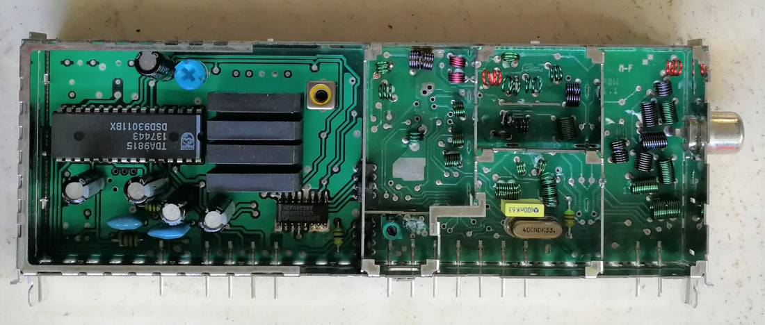
The Philips FQ916MF/L, with on the left the UV916H tuner section. Note the limited number of SMDs on the IF board on the right. The long IEC RF connector was required to keep dimensions compatible with the splitter types. [Hugo Duran collection]
Top view of the Philips FQ916MF/L. The three DIL IF-ICs that are required for the full Multi-France functionality are clearly visible and take up most of the space. Compared to the FQ800 the brown-coloured SAW filter has considerable been reduced in size. [Hugo Duran collection]
The IF section of the FQ900 was designed around the new TDA9802, a PLL demodulator like the Sanyo IC used in the FS916, but at 5V supply voltage instead of 9V. Other than that the concepts of the two ICs were almost identical, although the 9802 was able to demodulate both negative modulation standards as well as positive modulation (L/L'). The single FM sound demodulator was not used, but instead the TDA9820 dual PLL demodulator, which could demodulate both the main and second audio signals. For the main input the IC contained a built-in selection switch. In case also L and/or L' reception was required the dedicated AM audio demodulator TDA9830 was added, which required the SAW-filtered IF signal as input, and performed quasi-synchronous (using the clipped IF carrier as input) AM demodulation. Although, compared to the FQ800, the number of IF ICs increased from two to three, the system partitioning was much more optimal and the application circuit much less complex with especially fewer tank circuits that needed alignment nor external switching transistors. The FQ900 family was introduced as a running change in the FL1.10 and following versions of the FL1, FL2 and FL4 TV chassis from 1993.
Starting from the FL1.10, the high-end Feature Line chassis switched from the FQ800 to the FQ900L. The FL2 covered the 16:9 screen size. This is the 32PW962B from 1993, using the new using Black Line-S Crystal Clear screen. It featured 100Hz and PIP. [Philips catalogue via RadioMuseum.org]
|
Top down interior view of a similar FL2.24 set, the 28PW908B. On the left the FQ900 front end. [Obsolete Telly]
|
|
By the time the FQ900 was being defined, around 1991, D2MAC was in crisis due to the emergence of Astra satellite TV, but definitely not dead. It was expected that especially Cable-D2MAC, so D2MAC-coded signal distribution in cable-TV networks, would still become a serious application. Ever since the FQ800, and still in the FQ900, provisions for D2MAC were important. In practice this meant that the tuner IF output was made available, symmetrically, for an external D2MAC IF demodulator, followed by the D2MAC decoder. All FQ800 and FQ900 models used internally by BGTV have the IF-suffix, indicating they were D2MAC ready.
It seems that the BU Tuners also designed and offered a D2MAC IF demodulator to the TV Labs, either on their request or on its own initiative. This model had the functionality as shown in the circuit diagram below, the only reference I've seen for this module. 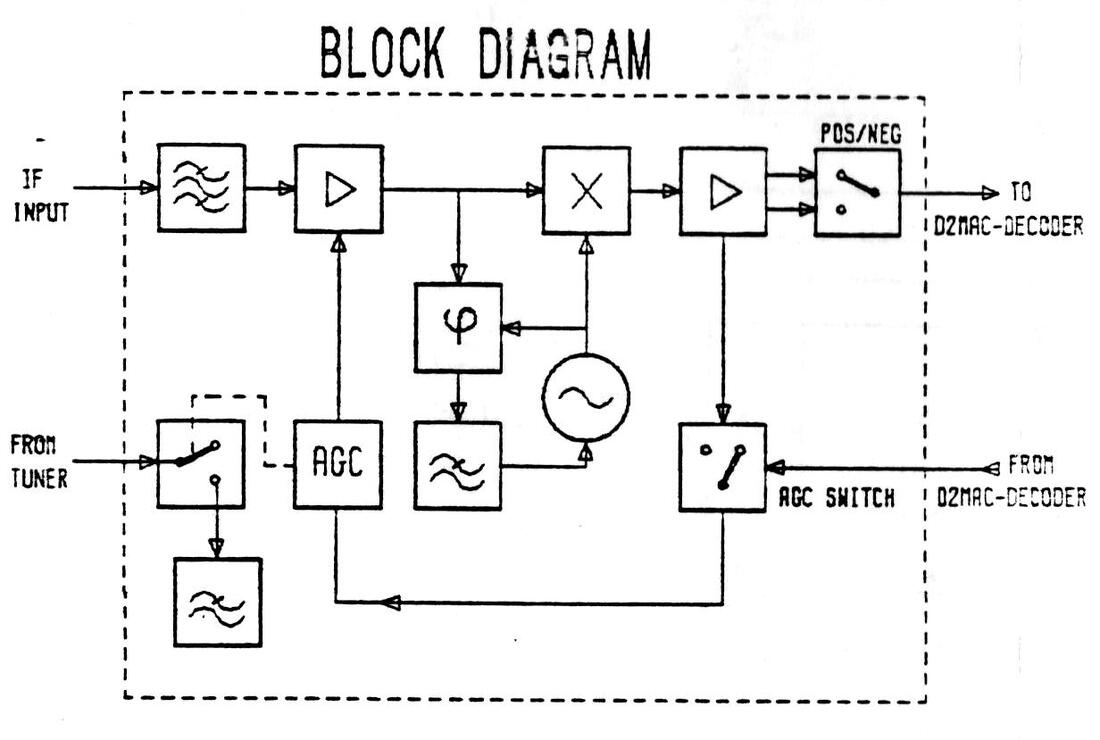
Block diagram of the Philips D2MAC IF demodulator module, intended to accompany the FQ800 and FQ900 front ends. [BU Tuners 1990 product overview]
The module essentially was a second down-converter, with a PLL locking to the D2MAC carrier. AGC gating and a positive/negative switch made it flexible to all possible D2MAC modulation formats. As said, there are minimal traces of this module, and I strongly doubt it was ever taken into production. Knowing the BGTV, they probably claimed doing it themselves better and cheaper. Despite all that, D2MAC was persistent, and when the next generation front end was defined it was called the FM900, the M explicitly referring to MAC.
The main challenge of the FQ900 family was the type diversity. There were the FQ916 basic version (B/G), ME Multi Europe (B/G/L/M), MF Multi France (L/L'/I/B/G) plus the FQ944 (I), as well as splitter versions of the multi-versions and IF-versions for D2MAC out. In all some 8 types for a modest 350k modules per year. |
The PS915 click-on PIP-splitter, 1993
As listed earlier, one of the requirements for the FQ900 family was to support dual tuner Picture-in-Picture (PIP). In that case a splitter module could be clicked in front of the FQ900 tuner section, reducing the normal IEC-long connector to a normal IEC. Broadband splitters are always a challenge, as we've already seen in the VCR module section in chapter 4, compromising between broadband gain, NF degradation and good IP2 and IP3 overload performance.
Three pictures of the PS915: with closed cover, SMD-side and bottom side. [Johan Bos and Martin Barnasconi collection]
The PS915 was essentially based on a single transistor amplifier directly behind the input, using a high power BFG97 amplifier. Normally the outputs were then connected through a balancing transformer. However, this did not provide sufficient isolation between the different outputs, and additional common base amplifiers were added in each of the output branches. Because this type of amplifiers does not add gain but only noise, overall performance of the PS915 was marginal.
FQ900 types using the PS915 splitter were marked D. So the FQ916DME was the Multi Europe type with splitter. 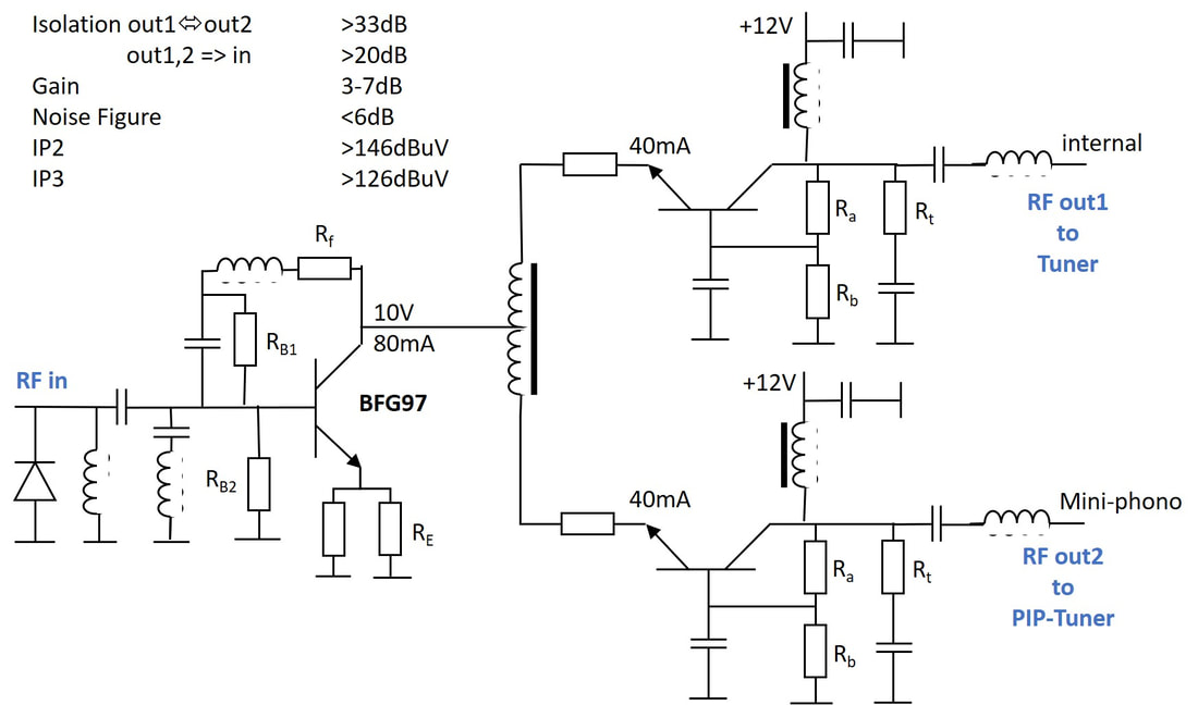
Approximate circuit diagram of the PS915 RF PIP-splitter. Rb1 and Rb2 set the base voltage of the BFG97; Rf/RE set the amplifier gain; Ra and Rb set the base voltage of the common base transistors; Rt sets the output impedance to roughly 75 Ohm.
|
Overview of the Philips FS900 and FQ900 TV Frontends. The FQ900D types used the click-on PS915 splitter module.
FQ900-Mk2, the last TV front end, 1995
The FM900, as the next generation was called with the M referring to D2MAC, was defined for the next generation high-end chassis, the Global Feature Line (GFL), targeted for launch in 1994 in Europe, Asia in 1995 and Latam in 1996, and intended to cover 24-32" 16:9 and 25-33" 4:3 screen sizes. Given the experience with the FQ900 the BU Tuners desperately tried to keep diversity limited, but the front end was clearly used to solve the BGTV regional diversity problems. The original request was 19 types: eight new FQ900-Mk2, one video-only FV900, the three existing FS900 and seven FM900. The BU Tuners, in contrast, pushed hard to have all multi-types covered by a single Multi-Global: main standards B/G/D/K/L on the main PCB, secondary standards M/L' on an add-on PCB. The type that in practise came closest to this ambition was the FV916MG, a version with no internal sound demodulation, so only video, for the typical Overseas countries. However, BGTV insisted on the by now standard ME and MF versions. The updates of the FM900 versus the FQ900 were:
- replacement of the UV916H tuner by the lower tilt UV916M, required for the D2MAC performance;
- a new multi version was introduced covering the D/K standard for Russia and Eastern Europe (remember that in 1989 the Wall fell) and China: Multi-Russia (B/G/D/K/I/M);
- use of the fully integrated Philips Semiconductors multi-standard QSS IF-IC TDA9815. This IC had dual VIF inputs, a PLL video demodulator with gated phase detector for L/L' and gated AGC for positive modulation, a QSS SIF demodulator which also acted as detector for AM sound, two FM demodulators for the main and sub-carrier and D2MAC mode (by-passing all audio circuitry);
- the D2MAC demodulator as optional sub-printed circuit board, where it is not clear on which IC this function was based;
- for the multi versions the IF required switching between four VIF SAWs, while on the sound sub-carrier level there were also multiple sound filters to be selected. For all this switching multiple transistors were required. So although the TDA9815 provided a much higher level of integration compared to the three ICs in the FQ900, the application became more complex;
- because there were now so many standard options and combinations, and especially so many different switches to control, the three control lines coming from the tuner I2C in the PLL were no longer capable of driving it all, and a digital decoder HEF40538 was required to manage the standards selection;
- the PS915 was still required for PIP versions, but the front end input was no longer the TV set antenna connector, so all connectors became phono. Although there were some investigations into an improved Mk2, due to low volumes it was decided to stay with the PS915-Mk1.
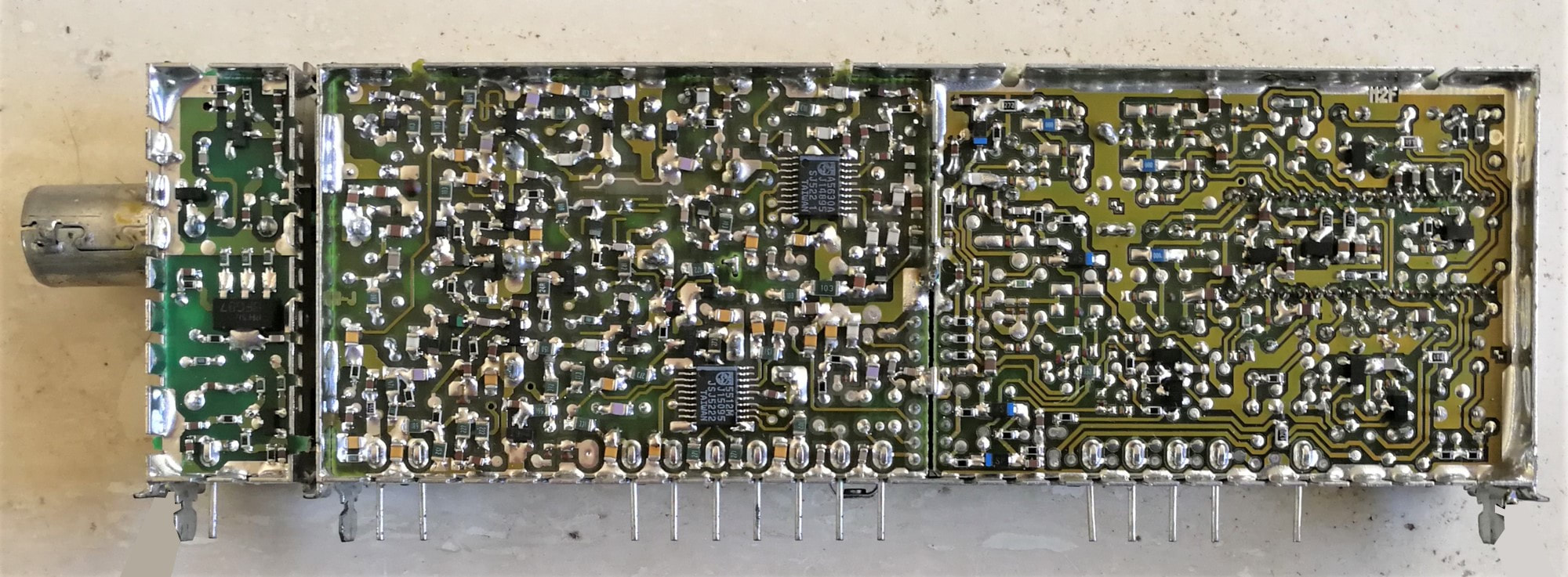
A-side picture of the Philips FQ916DMR-Mk2 multi-standard TV front end with PS915 splitter on the left. Note the many switching transistors on the IF PCB. [Johan Bos collection]
B-side picture of the Philips FQ916ME-Mk2. The TDA9815 fully integrated multi-standard IF IC as well as the 4 SAW filters (3 video, one sound) are clearly visible. [Hugo Duran collection]
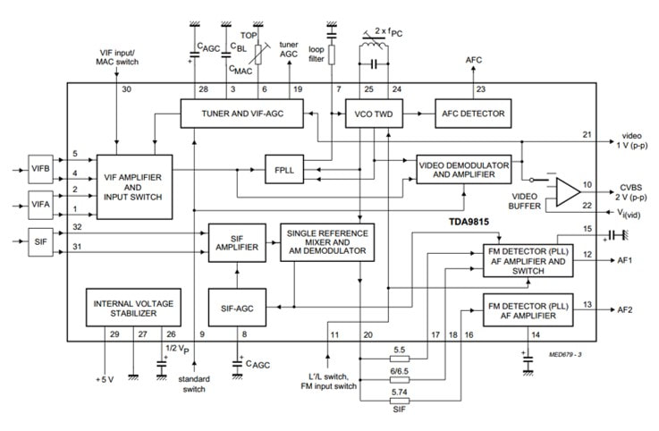
Block diagram of the Philips Semiconductors TDA9815 multi-standard fully integrated IF IC, with PLL Video-IF demodulation, and single-reference Quasi Split Sound (SR-QSS) sound-IF demodulation re-using the same regenerated picture carrier frequency. The IC has provisions for dual VIF inputs and triple second-SIF sound sub-carriers. [Philips Semiconductors TDA9815 Data Sheet]
The only chassis using the FQ900-Mk2 frontends was the Global Feature Line. Here a 4:3 screen version of the GFL2.20, the 33" 33PT9121.
|
A widescreen 16:9 version of the GFL chassis, the GFL2.30 32PW9761.
|
|
The history of analogue TV front ends between the BU Tuners and BGTV was not a happy one. One reason was technical: front ends were originally defined to match the tightening Cenelec norms on radiation, where it was expected that both functions in a single metal can would improve especially radiation ingress performance. Which was true, but unfortunately not necessarily the only possible solution, so in the end there was no urgent need for TV to use front ends. Also there was no functional integration or design advantage of having both in the same box, they were literally two separate PCBs put into one frame. But the main reasons were political!
The first generation FS600 suffered from cover contact fretting corrosion, which gave the BU-T quality reputation a serious dent. When this problem was structurally solved - by soldering the cover contacts - the High End Lab and Brugge TV Development returned to the FQ800 family, which was high performance but also high price. An FQ800-multi price at the time was around 55Hfl, a considerable part of the total TV Bill-of-Material (BoM), and this was one of the main reasons these front ends never came into the standard segment (the Dreux Anubis chassis). The main problem with BGTV was that they didn't provide a stable application, allowing the families to run for a number of years to recover the fairly high development costs. The FQ800 was introduced in the FL1 and FL2 chassis in 1991, to be replaced a so-called "running change" in 1993 on the same chassis with the FQ900-Mk1, which in turn was replaced by the FQ900-Mk2 (after a lot of wasted D2MAC development costs) in the GFL in 1995. So the volume life time of each generation was only two years, with increasing complexity and performance requirements, and all that for a total volume of, at the peak in the GFL chassis, 450.000 units per year. Where the combined volume of the ME and MF main runners was already 370k, and in contrast that of the combined PIP D-versions less than 13k pieces. At the same time every sub-type had to go through the same full release procedure. To add insult to injury the splitter versions were even completely dropped in 1994, the splitter moving to the UV1216D which will be discussed further down. It is obvious that under these conditions the front ends were a seriously loss making business for the BU Tuners, and a strain on the internal BGTV-BUT relation. It was therefore a relieve to both parties when BGTV decided end of 1993 that they didn't require any new front ends after the FQ900-Mk2 family. There was a short discussion on the request to build IF modules for material plus 0,50Hfl, but this obviously didn't lead to any agreement. This ended the 10-year story of front ends in Philips TVs. |
A last, and probably very low volume, application of the FQ900-Mk2 frontends were the FTV1.5 and FTV1.9, the very first plasma TVs of Philips from 1997-1998. Here the FTV1.5 42PW9962. The screen only contained the display driver electronics, the small signal electronics were contained in a separate E-box, as were the speakers.
The FTV1.9 E-box, containing either an FQ916ME or FQ916DMF as primary tuner. For PIP it used the UV1216D or FI1236 front end. [Philips FTV1.9EE Service Manual, 1998]
|
Overview of the Philips FQ900-Mk2 family of analogue front ends for TV. The trend towards increasingly multi-standard solutions is obvious.
TP900, VCR tuner-modulator, 1996
In the VCR domain the Wien factory in Austria tried to stay competitive against the Asian competition by using high levels of automation, whereas Grundig continued production in its renewed factory Werk21 in Nürnberg. In 1992 the two companies, although now both owned by Philips, create the the separate joint venture (60% Philips) "Image Reception, Recording, Replay"or in short iR3, which from then on contains all VCR activities. The iR3 construction allows a further strengthening of the co-operation with Panasonic/JVC and its Kuala Lumpur, Malaysia factory. In the Philips model range we thus see the occasional Panasonic set (re-branded as Philips) and an increased use of Matsushita key components like modulator modules.
As explained in the previous chapter, the relation between the BU Tuners and the VCR business in Wien (Vienna, Austria) remained difficult. The VCR business was the first to drop the notion of vertical Philips purchasing, instead buying many components, modules, complete decks and sometimes even complete sets in Asia. One of the worrying elements was that this was now hailed by the Consumer Electronics management, and around 1995 iR3 - after many years being left alone and ignored following the V2000 debacle - was now all of a sudden hailed as a shining example for the other CE groups (TV and Audio). The desastrous effects of this we will see in the years to come! With the 1990 Jasmin chassis a Philips tuner (the UV916E) had been re-introduced, but the splitter-modulator module remained Asian (Alps, Mitsumi, Samsung). The BU Tuners thus had to do a lot of talking to convince Wien to use Philips tuners. The difficulty in the discussions was the big cost pressure in VCR, Philips/iR3 only being a small player, with price references set by the big and homogeneous US VCR market (20Mio of the global 48Mio sets VCR market). In this segment Alps had a major position, producing so-called NTSC 3-in-1's, that is a single module containing splitter/modulator, tuner and single-standard IF. It was obvious that given the European and Asian IF diversity (B/G, D/K, I/I', L/L') it was not economical to make non-NTSC 3-in-1's, so the target became the 2-in-1: splitter/modulator plus tuner. But with aggressive price targets based on 3-in-1 single-standard references. This became the TP900.
As explained in the previous chapter, the relation between the BU Tuners and the VCR business in Wien (Vienna, Austria) remained difficult. The VCR business was the first to drop the notion of vertical Philips purchasing, instead buying many components, modules, complete decks and sometimes even complete sets in Asia. One of the worrying elements was that this was now hailed by the Consumer Electronics management, and around 1995 iR3 - after many years being left alone and ignored following the V2000 debacle - was now all of a sudden hailed as a shining example for the other CE groups (TV and Audio). The desastrous effects of this we will see in the years to come! With the 1990 Jasmin chassis a Philips tuner (the UV916E) had been re-introduced, but the splitter-modulator module remained Asian (Alps, Mitsumi, Samsung). The BU Tuners thus had to do a lot of talking to convince Wien to use Philips tuners. The difficulty in the discussions was the big cost pressure in VCR, Philips/iR3 only being a small player, with price references set by the big and homogeneous US VCR market (20Mio of the global 48Mio sets VCR market). In this segment Alps had a major position, producing so-called NTSC 3-in-1's, that is a single module containing splitter/modulator, tuner and single-standard IF. It was obvious that given the European and Asian IF diversity (B/G, D/K, I/I', L/L') it was not economical to make non-NTSC 3-in-1's, so the target became the 2-in-1: splitter/modulator plus tuner. But with aggressive price targets based on 3-in-1 single-standard references. This became the TP900.
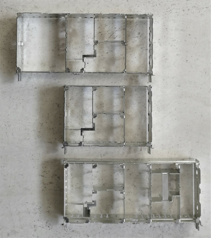
The 900-family frame design was flexible, and could be extended backwards (behind the tuner, top) or forwards (in front of the tuner, below). In the picture from top to bottom the FS900, UV900 and TP900 frames. RF input always on the right side. [Hugo Duran collection]
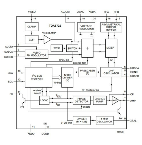
Block diagram of the Philips TDA8722 PLL-controlled UHF video modulator. [Philips Semiconductors TDA8722 Data Sheet]
|
To make the TP900 as cheap as possible it was based on the lowest cost European tuner available, the UV916E, the product already in use by iR3. So where all other tuner generations in development at this time used an MO-IC, the TP916 was the last product still based on a discrete mixer-oscillator. The functionality and characteristics were as follows:
|
|
One of the main drawbacks of any VCR up to now was that the loop-through splitter always needed be active, even if the VCR was not used, to guarantee signals were passed to the television RF input. Due to their high linearity requirements, loop-through splitters consume quite some power, and therefore the stand-by power of VCRs was always high. Furthermore, at least according the internal Philips rules for component guaranteed lifetime performance, junction temperatures of permanently-on devices needed be lower than 100degrC, which meant large devices or a lot of heat sinking. The perfect solution to all this was the Passive Loop-Through (PLT) function, which was proposed as new feature for the TP900. Although the reception by Vienna was lukewarm (it was of course not for free) it was nevertheless made a main element of the product and available as option (TP900L).
|
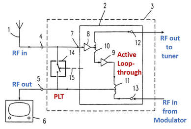
Block diagram of the TP900L with passive loop-through (block 14 with its control terminal 15). [Philips US patent 5,706,060 by Leo Ruitenburg, filed April 1995]
|
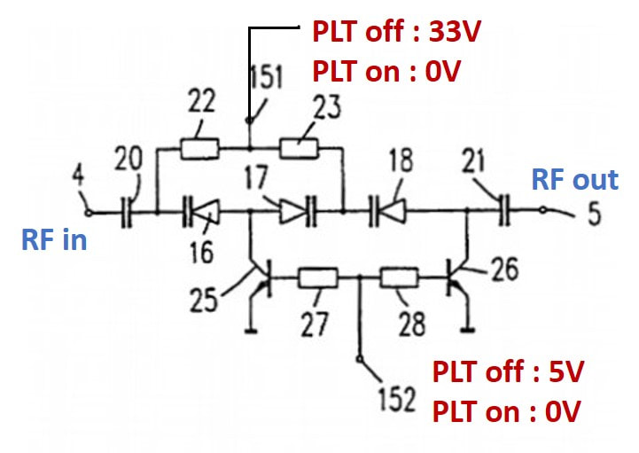
The basic circuit of the Passive Loop-Through, using multiple series-connected varicaps. [Philips US patent 5,706,060]
|
The PLT was based on a patented solution using the latest high-ratio varicaps. The basic concept uses the fact that at zero Volt the capacitance of a varicap is high, while it becomes low at 28V. The BB1147 capacitance, for example, varied between some 100pF at 1V and 2,5pF at 28V, a ratio of 40. During normal operation of the splitter-modulator, the voltages on the PLT control terminals are high: 33V at terminal 151, 5V at terminal 152 and thus 0V at the varicap anodes. The capacitance of the varicaps is consequently low and the equivalent impedance parallel to the active loop-through high. If the impedance of a single varicap is too low in the on-state, multiple diodes can be connected in series; the Philips patent goes as high as four. For example, at 1GHz, C28 of 2pF per diode and three diodes in series gives a total impedance of 240 Ohm. When both control voltages 151 and 152 are switched off at 0V, the diode voltages become 0V too and the capacitances high, providing a low-Ohmic path between in- and output. The design of the TP900L PLT is based on the three-diode circuit shown left, although in practice the 2nd diode 17 was replaced by a capacitor for saving cost. The typical insertion loss of the PLT when in use was 3dB.
|
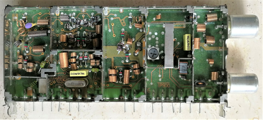
Top view of the Philips TP916 Tumod, with on the right the splitter-modulator section. [Ronald Dekker collection]
|
SMD side of the TP916. On the right the UV916E tuner section with the TSA5512 PLL lower right, on the left the modulator IC TDA8722M. Above the IC near the upper side the power transistor is visible. [Ronald Dekker collection]
|
The TP916, upper left, in a Paolina chassis VR668 from 1996. [MFB-freaks]
A TP916L.
The new Passive Loop-Through (PLT) of the TP900-Mk2, using the new Philips Semiconductors BF1107 MOSFET. [Philips RF Manual, 4th edition, 2003]
|
The TP900 was released early 1996, and although developed in Krefeld was volume produced in Singapore and Batam, in view of the required volumes and the cost. The total VCR volumes of Philips at this time were 4,5Mio sets per year: 2,25Mio standard Europe (TP916 system G), 50k Eastern Europe (TP956 system K), 500k France (TP926 no modulator), 300k UK (TP944 system I UHF only) and 20k Ireland (TP946 system I). After much discussion it was decided that all Grundig Neurnberg sets would use the PLT while all small volume types (944, 946 and 956) would only be produced with PLT. However, now the iR3 politics (or was it the Consumer Electronics or even Philips politics?) kicked in again, because the Vienna organisation had forced Alps to develop pin compatible copies of the TP900 family, including a PLT. In contrast to the BU Tuners, who never made any Japanese pinning products, Alps did develop a Philips-pinning TP900 family (called TMRG1), probably the only time they ever did this. Vienna decided that 15% of the volume including the small volume versions went to Alps, leaving the TP916 and TP926 main runners to Philips. From a production and diversity perspective this was not bad, although it didn't reduce the development effort, since all versions needed release anyway. Later the Alps percentage increased to 40%.
The TP900 family didn't live long, because it was quickly succeeded by the TP900-Mk2, based on the UV916S tuner discussed in the previous section, including its single-sided re-flow technology. The modulator remained unchanged, but the passive loop-through was improved by switching to a dedicated single-gate MOSFET, based on the same 0,5u technology as used for the latest generation dual gate MOSFETs. The BF1107 was a depletion-mode type, which was operated in a grounded-grid configuration. The Drain-Source voltage was always kept equal to zero by the series capacitance in the Source. In normal VCR operation the Drain is connected to 5V, and with Vds=0 the Source too. The Gate-Source voltage Vgs is thus -5V, far beyond the -3V pinch-off voltage, and the MOSFET doesn't conduct, leaving the loop-through function to the normal active splitter. However, in stand-by, with Vd=0V too, both Drain, Source and Gate are all at 0V, the MOSFET conducts and thus provides a (12Ohm resistive) RF path to the output. To avoid capacitive load of the inoperative active splitter, two additional switching diodes are added.
|
The TP900-Mk2 was introduced in the new Apollo Turbo-VHS platforms in 1998 to 2000 (Apollo10, 11, 12 and 20), again alongside some 40% Alps copy models. In the end the TP900 families lived for only 5-6 years, amounting to some 15Mio products and 300MHfl sales.
By this time the VCR was rapidly loosing its position as carrier of video content to the (recordable) DVD, and became a very low cost commodity product. As part of the required cost cutting production in the Wien factory was stopped, and transferred to Shékesfehérvár, Hungary in 1997. But did not stop the trend. In the US Philips/iR3 stopped manufacturing its own VHS recorders per the same year, the Japanese company Funai taking over production of all Magnavox-branded VCR decks. Ironically they were very successful, being the first to introduce below 100$ VHS recorders. In 2001 Philips, the majority shareholder in iR3, threw in the towel and sold all remaining VCR business to Funai. Although they continued to sell Philips-branded products (Philips in Europe, Magnavox in the US) the chassis quickly became Funai-designed using Japanese components, and all prospects for Philips tuner-modulators were gone. Funai stopped production in Hungary end of 2009.
By this time the VCR was rapidly loosing its position as carrier of video content to the (recordable) DVD, and became a very low cost commodity product. As part of the required cost cutting production in the Wien factory was stopped, and transferred to Shékesfehérvár, Hungary in 1997. But did not stop the trend. In the US Philips/iR3 stopped manufacturing its own VHS recorders per the same year, the Japanese company Funai taking over production of all Magnavox-branded VCR decks. Ironically they were very successful, being the first to introduce below 100$ VHS recorders. In 2001 Philips, the majority shareholder in iR3, threw in the towel and sold all remaining VCR business to Funai. Although they continued to sell Philips-branded products (Philips in Europe, Magnavox in the US) the chassis quickly became Funai-designed using Japanese components, and all prospects for Philips tuner-modulators were gone. Funai stopped production in Hungary end of 2009.
The TP900(L)-Mk2 externally looked identical to the Mk1. Here the TP916L-Mk2.
Right: the TP916-Mk2 in an Apollo12 chassis VR200/02 from the year 2000. [van Eck Video Services]
|
|
Overview of the two generations Philips TP900 Tuner-Modulators (Tumods) for the VCR market.
Almost in parallel to the TP900 Tuner-Modulator, a second segment was addressed between iR3 and the BU Tuners: TV-VCR combis. The VCR drive was becoming so cheap - the main problem of iR3 - that it became econiomically feasible to put a VCR drive into a standard TV set. The first platform called Alpha (but more commonly TV-VCR1) was launched in 1995. It used the Anubis-A low-end TV chassis from Monza as a starting point, which used the UV917 VST tuner. It was plobably only a trial, with very few actual models. It was the only TV-VCR to have the VCR unit above the TV, all next generations would have it below. The TV-VCR1 also seems to have been the only produced in Monza, the mother fab of the Anubis chassis. (In parallel all US TV-VCRs were also developed by Funai, coded CCA or CCB, and produced in Malaysia).
Now, for TV-VCR there were two options:
Now, for TV-VCR there were two options:
- cheap sets used the single tuner of the television chassis, which meant that only the TV channel being watched could be recorded.
- more expensive sets had a second tuner on the VCR board, allowing the recording of a different channel than the one being watched. These second tuners were the uV1216D with splitter, the output of the splitter looped-through to the TV tuner.
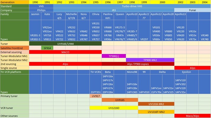
Overview of the Philips VCR and TV-VCR generations and their RF module sources from 1990 till the take-over by Funai in 2002.
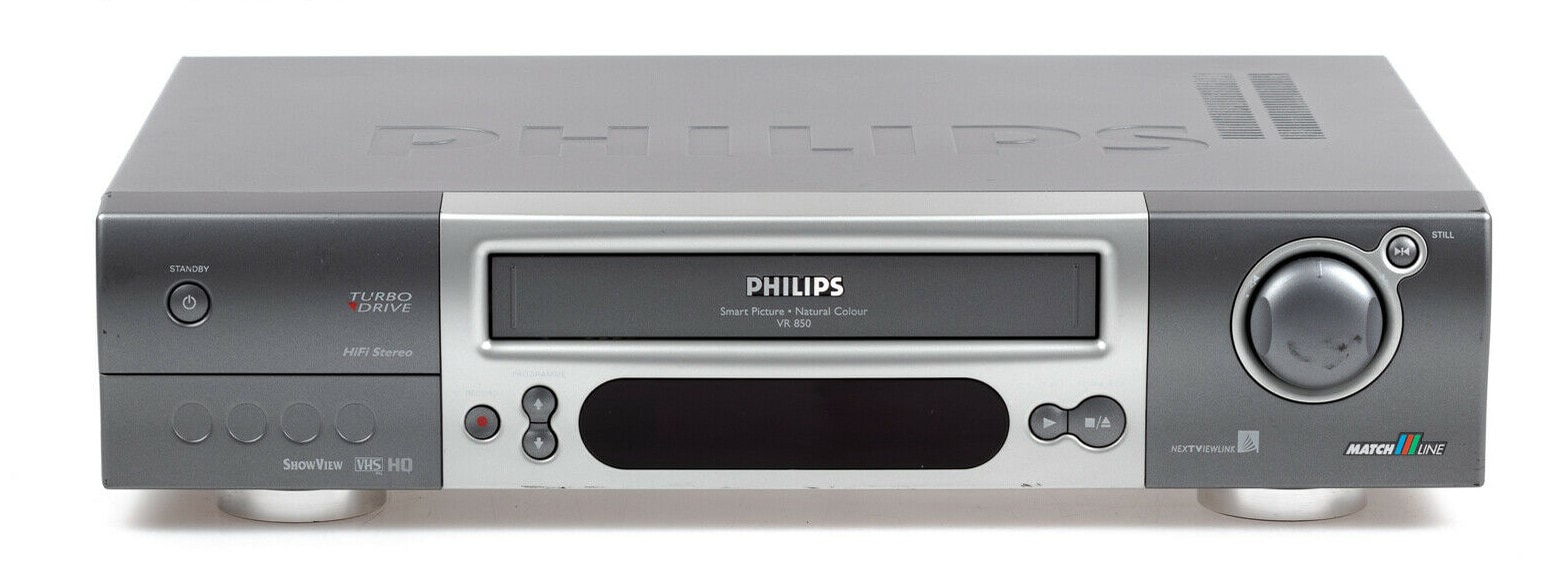
The end of the VCR era. This is the VR850 Matchline VCR from 2000, one of the last models that used the Philips TP900-Mk2 tuner-modulator.
|
One of the last VCR recorders sold under the Philips brand, but developed and produced by Funai, the VR740 from 2002.
|
The last TV-VCR developed by Philips/iR3, the Delta chassis 14PV334. It used the UV1300 new tuners.
|
The last Funai developed and produced TV-VCR branded as Philips, the Epsilon chassis. This is the 21PV385 from 2002.
|
UV1200 Miniaturization and PIP, 1992
|
As already mentioned earlier, one of the issues haunting the Philips Tuner organization was the substantially smaller size of the Japanese tuners. Although Philips was perfectly competitive on performance (and often still the benchmark) and price, the smaller size always gave discussions. Perception was that bigger was less advanced. So once the UV900 family reached production in 1990 development started of a substantially smaller tuner family: the UV1200. The challenge with miniaturization in the meantime remained as it will always be: in general smaller size means less material and thus lower cost, but beyond a certain point the technology to make a product smaller also makes it more expensive, often due to the need for new components. Because volumes are still low, prices are higher. For Philips Tuners an additional cost adder were investments, since completely new manufacturing processes were required.
|
Mechanics of the UV1200, the smallest Philips tuner to date.
|
UV1216E top view (B-side) and bottom view (A-side). This was the first generation UV1200 tuner, still based on the UV916E discrete concept. [Hugo Duran collection]
Note on the above two pictures: since this was a manufacturing prototype the IC and 4MHz crystal were not mounted. To give the impression of the complete product I've copy-pasted them into the pictures.
|
The main challenge for miniaturization was the need to move to a more advanced soldering process. Wave soldering used up to now was reaching its limitations: smaller components (0603 or SSOP ICs) could no longer reliably be wave soldered without the risk of short circuits. The solution for this was well known: re-flow soldering, where a solder paste is printed on the PCB before the components are placed, and the solder joint is made during a pass through the re-flow oven. The first exercise was the UV1216E, essentially a copy of the UV916E scaled to the much smaller 1200 size. The innovations were thus in the mechanical and process domains:
The UV1216 now made a split into two different directions, not dissimilar from the UV800 earlier: the main application became the tuner being the tuner section of the new FI1200 multi-media front end family. This would become the by far biggest application, for many years. The second track was the UV1216 as second tuner in TV-VCR or Picture-in-Picture TV applications, in these cases often as splitter-tuner. the original intention to make the UV1200 the new main tuner family as successor of the UV900 were quickly dropped, also because the intended leading TV chassis Horus, the Steco successor of the Anubis chassis, was cancelled. The Anubis saw multiple upgrades, stretching its life till 1997 when it was succeeded by the L7 chassis. |
|
Since the UV1200 was not cheaper than a standard UV900, it only found application where it was worth paying for a small tuner. The first one was the TV-VCR (or TVCR) combo, a secondary product line of the iR3 organization in Wien and Neurnberg (Grundig). These TV-VCRs were positioned as cheap small size alternatives to separate TV and VCR, and were mainly using small 14" to 20" screens. In cabinets barely larger than a standard 14" TV but now also including a VCR deck there was obviously not much room for large modules. The first generations TVCR were based on an Anubis-A CTV chassis in combination with standard VCR drive. In case of single tuner sets the standard UV917 tuner was used on the Anubis chassis, but for a dual-tuner that was replaced by the UV1216D (with the same length) from which a small coax cable then ran to a second UV900 tuner on the VCR board. All tuners were standard vertical mounting. The TV-VCR Gen1 was introduced in 1994, the Beta chassis in 1996 and the Mono98 in 1998, all using the UV1216D/P.
The second application was Picture-in-Picture, which at the time was seen as a major TV innovation, after the death of D2MAC and with the upcoming 16:9 widescreen television. PIP was initially only implemented in the high-end Brugge chassis, where an add-on module with a complete video processing chain was added to the basic chassis. The very first PIP set was the FL1.14 Feature Line, but still using a vertically mounted UV916E. The GFL2.20 in 1995 introduced the horizontally mounted UV1216 on a PIP plug-in panel. In these chassis the splitter was part of the FQ900 front end as has been discussed. The life of the UV1216 in high end sets was as limited as that of the FQ900, so just one chassis. |
A typical medium sized screen Philips TV-VCR, the 20" 20PV184, with the VCR deck below the TV screen. This model was based on the 1998 Mono98-chassis. [Philips]
The splitter/loop-through RF output for the UV1216D/P as used in TV-VCR sets was a mini-phono through the top cover.
|
Philips UV1216D/P splitter-tuner, with TDA5731 MO-IC and TSA5518 PLL. [Johan Bos collection]
|
The UV1216 tuner. This module was also the tuner section of the FI1200 multi-media front ends. [Johan Bos collection]
|
|
Although the UV1200(D) was not a major business success (volumes remained quite low), it was an important technology innovation step, introducing a few new features:
|
A rare picture of the inside of a GFL2.20 PIP chassis, with on the right the FQ916DMR with click-on splitter, and left of it the PIP panel with the UV1216 (hor). [Espec WS forum]
|
Overview of the Philips UV1200 family of small-size (splitter)-tuners.
SF1200 satellite front ends, 1993
|
In the meanwhile the satellite broadcast market had fully taken off, and especially Astra (continental Europe) and BSkyB (UK) were rapidly growing in the numbers of satellites deployed and subscribers watching satellite TV. The market growth was a spectacular 20%/year, with in 1993 a European market of 3,5Mio sets/year and world-wide 7,5Mio sets, predicted to grow to 22Mio/year by the year 2000. Most interestingly, the dominant players on the consumer side were not the classical consumer electronics or TV makers, with the exception of Grundig. Other players were new in the consumer domain, although often with a history in more professional (satellite or RF) equipment: Kathrein, Amstrad, Pace, Technisat and Luxor, to name the biggest ones. Philips, which as we have seen in the previous chapter gambled on D2MAC for too long, almost entirely missed the Astra-based market and had a humble 3% market share, often based on complete set top boxes purchased and relabelled from one of the bigger players (like Pace). Nevertheless a new group was established in Eindhoven and Suresnes (Paris, France) that started working on satellite receivers.
|
|
Mechanical outline of the Philips SF1200 satellite front end family.
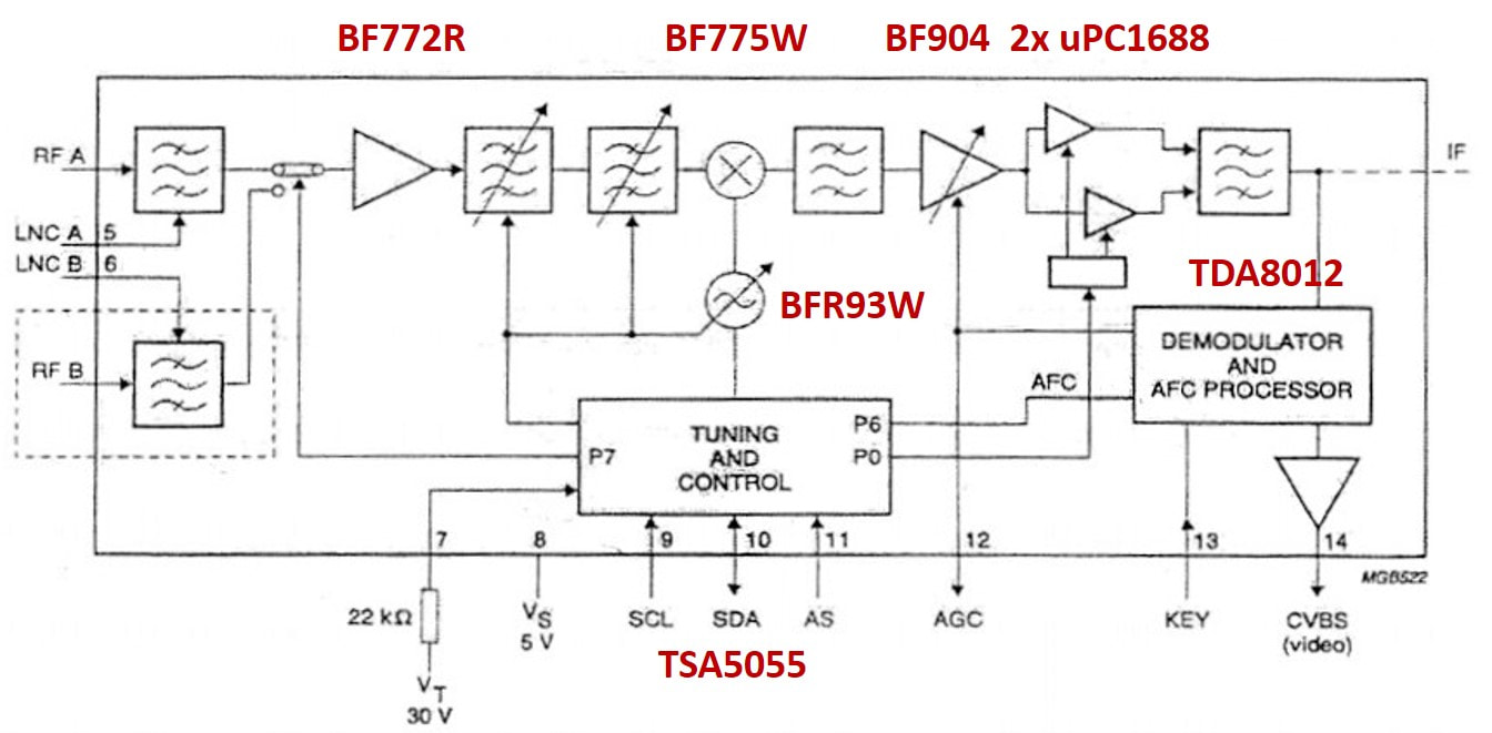
Block diagram of the Philips SF1200 satellite front end family. The three options dual input (D), switchable IF bandwidth (W) and IF output (A) are included. [Philips Components SF1216 Data Sheet, 1995]
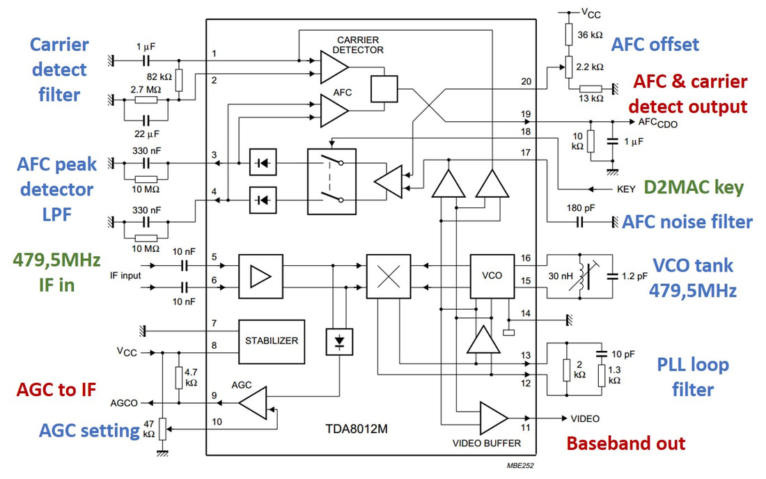
Block diagram of the Philips TDA8012 satellite PLL IF demodulator IC. Input signals green, outputs red, functions blue. [Philips Semiconductors TDA8012 Data Sheet]
|
The previous Philips satellite front end had been the SF916, launched in 1991 and using a modified UV900 housing. However, by that time it was already outdated with respect to size. Competition was offering much smaller satellite modules for the Set Top Boxes (STB) that quickly became thinner. The satellite front end was thus one of the most urgent application areas for the introduction of smaller modules, and consequently the first to adopt the 1200 family mechanics. Also because this was the only option for offering horizontal mounting. In contrast to the UV1200, which used reflow soldering, the SF1200 continued to use the cheaper wave soldering, with the exception of the SSOP IC on the B-side. Compared to the SF916 it introduced the following new features and components:
|
- the receiver has a two-step AGC: first the IF is controlled using the BF904 dual-gate MOSFET, when more gain reduction is needed the RF PIN-attenuators kick in;
- the SF1200 offered the switchable IF bandwidth option, where there were essentially two configurations compared to the standard 27MHz IF bandwidth as used by Astra: switching to 32 or 36MHz as used by higher bandwidth modulation formats. Or switching to the lower 18MHz bandwidth to provide threshold extension for Astra signals. In the latter case, with high noise due to a weak received signal, the SNR can be improved by reducing the noise bandwidth from 27 to 18MHz. Switching is controlled through port P0 of the PLL.
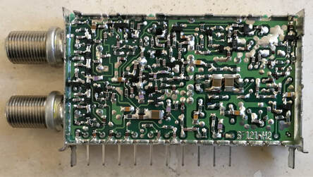
SMD (A-) side of the Philips SF1216/FW2732 satellite front end. This side is still wave soldered. [Johan Bos collection]
|
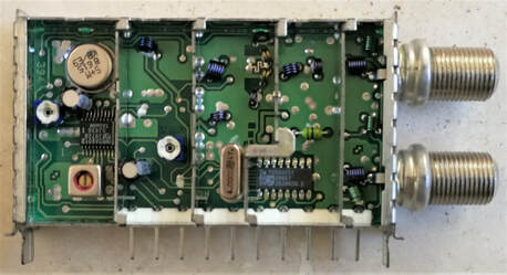
Component (B-side) of the Philips SF1216FW2732 satellite front end. On this side only the two ICs are reflow soldered: the TSA5055 on the right, left the TDA8012 IF demodulator. [Johan Bos collection]
|
The SF1200 was quite successful on the satellite market in terms of speed of design-in and the ramp of volumes. The modules were used by the Philips Suresnes STB, as well as the CTV satellite add-on modules. The latter were a last desperate attempt by the CTV organisation to keep satellite within the TV domain. However, these TV satellite cards were only fit for so-called "free-to-air" uncoded channels, whereas the majority of the most popular channels broadcast by Astra and the likes disappeared "behind the decoder", only visible with a subscription and card. (This ignores the massive hacking of the early analogue conditional access systems, but that didn't change the problem for the TV makers). A single plug-in satellite module was developed for the GR2.2 and GFL chassis based on the SF1216, but sales were minimal. After a last try with the Mid1 chassis satellite was dead within the Philips TV chassis, from now on satellite reception was exclusively the STB domain.
|
The next development in the satellite domain was the band extension of the Astra satellites, where next to the Enhanced Astra band from 10,7-11,8GHz now also the so-called Universal Astra band was added, from 11,7 to 12.75MHz. The challenge with this new band has already been introduced in the previous chapter, and is illustrated in the figure on the right. With the "default" LNB LO-frequency of 10,75GHz the first IF (and thus the input frequency range for the satellite front end) would be 950-2000GHz, within the normal SF1200 range. However, in this case the beat frequency of the two LOs (10,75-9,75=2,0GHz) would fall within the satellite IF band, see the top part of the figure. The upper LO was therefore shifted down to 10,6GHz, shifting the beat to 850MHz outside the 1st IF band, but now the 1st IF range became 1100-2150MHz. (The 2nd order beat 2xLO2 - 2xLO1 now appeared at 1700MHz, so within the band, but because of the 2nd order the power level of this interferer was acceptably low).
|
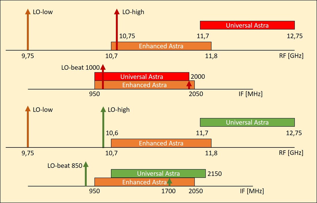
Illustration of the need for 1st IF band extension to 2150MHz with the introduction of Universal Astra reception. The top (red) scenario gives unacceptable beats within the receive band, the chosen (green) lower scenario not.
|
|
The 2150MHz coverage SF1218 was first introduced as a selection of the SF1216, which in most cases had sufficient tuning reserve to meet this new spec. The new feature was also used to introduce a simpler and more compact coding scheme of the satellite front ends. The structural implementation of the 2150MHz range was combined with the SF1200-Mk2. This was driven by the need for cost reduction, since the satellite market was under severe cost pressure. The Mk2 saw a number of cost savings:
|
Starting with the SF1200-Mk2 a new product coding scheme was used for satellite front ends. In general it was SF1234(P)ABC
|
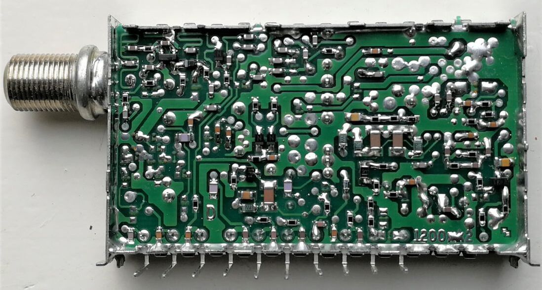
SMD side of the Philips SF1218K-Mk2 satellite front end. Note the improved placement accuracy and smaller SMDs compared to the Mk1 products. [Jac Janssen collection]
|
B-side of the Philips SF1218K-Mk2. There are now three SSOP reflow soldered IC's, with centrally the new TDA8010 MO-IC. [Jac Janssen collection]
|
Overview of the SF1216 and SF1218-Mk2 satellite front ends. Note the change of coding convention with the introduction of the 2150MHz.
Telephone modules, 1991-1995
Another new application, not covered so far, is wireless communication. These standards use by definition radios for transmission and reception, always bi-directional, and these radio modules obviously fell within the scope of potential new business for the BU-T. At the same time we should not forget that by the end of the 1980s this was really new for consumer applications, and initially the number of use cases was limited. The first application was the in-house analogue FM cordless phone of the CT0 standard, which had the advantage that only a limited range of some 10-20m was required. The problem was that many countries had their local CT0 standards with respect to downstream and upstream frequencies, so the BU developed only a few versions: CT012 for Spain and The Netherlands (31MHz base-to-handset, 40MHz return), CT024 for France (26 and 41MHz) and the CT034/54 for the US and China. The modules were based on a Semiconductors chip set and, given the low frequencies, didn't require a metal housing, so they were essentially stuffed PCBs. Which immediately highlighted the issue with these type of modules: there was not much RF competency required, neither for design nor for production (e.g. coil alignment). The CT0 modules were produced for the Philips Communications organization in Le Mans, France, and between 1991 and 1995 the volume steadily grew to 1,2Mio units/year.
Then in 1995 CT0 volumes completely evaporated because it was replaced almost overnight by CT1 and CT1+, still analogue FM but operating at considerably higher frequencies in the UHF band: CT1 at 914 and 960MHz, CT1+ at 885 and 932MHz, which were used in most of Europe and Germany, respectively. CT1 provided 40 channels spaced 25kHz apart, CT+ 80 channels. The BU developed modules for both CT1 and CT1+, the CT912/914 and CT916/918, based on a Philips chipset consisting of the SA601 RF LNA, SA626 FM demodulator and UMA1015 PLL. It still used a discrete LO and filtering, so here the RF design content was much higher. CT1 quantities ramped to 240.000 units in 1995, but then collapsed like CT0, to be replaced by the "ultimate" Digital European Cordless Telephone standard (DECT). However, DECT was from the beginning highly integrated and for cost reasons designed directly on the cordless phone main PCB, without an RF module. This thus was the end of cordless phone modules by the BU.
The Philips CT918B RF module for CT1+ analogue cordless phones. Production date was August 1994. [Johan Bos collection]
|

Top side of the Philips CT918B. Visible are amongst others 2 crystals and three filter modules. But upper right also discrete input filters and LO tank. [ibid]
|
SMD side of the CT918B with the three Philips RF ICs left to right: SA601A RF LNA, SA626 FM demodulator and UMA1015 PLL. [ibid]
|
The next application to emerge was the analogue mobile phone. While Europe quickly converged on the digital GSM standard, other areas started with (very big, shoe box size!) analogue mobile phones. The UK, Ireland, Italy, Singapore and Hong-Kong used ETACS (Extended Total Access Communication System), while the US used the very similar AMPS (Advanced Mobile Phone System). Like CT1 they operated in the UHF band just above the highest TV channel 69, although at substantially higher transmit powers to bridge the much larger distance. Philips developed a module for each of the two standards: the CA934 for AMPS and the CA944 for ETACS. But by the time these were launched (1995) the standards were already 10 years old and on the decline, given the emergence of digital standards. Furthermore, and in contrast to CT1 although at roughly similar frequencies, the AMPS and ETACS radios contained much more complex sub-functions, which were in-sourced as complete modules inside the CA934/944: a big antenna diplexer filter, an oscillator module, a PA module and a very narrow SAW filter. This made the purchased bill of material very high, and the margin for BU Tuners extremely small. When Le Mans switched to GSM completely also AMPS and ETACS were quickly discontinued. By 1997 it was all over for the telephone modules, when the last 100k were produced.
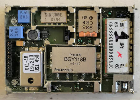
The Philips CA944 ETACS module. At the bottom left to right the oscillator, PA and diplexer modules. On the top row the SAW and an IF filter. Only the BGY118B, a silicon RF power amplifier from Nijmegen was a Philips module, all others were purchased. [Johan Bos collection]
|
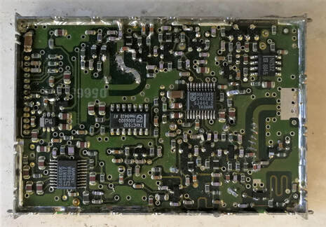
The SMD side of the CA944 module. The two most important ICs are lower left the SA616 FM IF/demodulator, and third from left the UMA1015 cellular PLL. [ibid]
|
FI900 and FI1200 Multimedia frontends, 1992-1995
While the "big" TV front ends, i.e. tuner plus IF demodulator in one box, remained a difficult and loss-making struggle, another front end application emerged with much better prospects. By the early 1990-ies the Personal Computer (PC) from IBM and its many clones, then based on the Intel 80486 processor families (with around 100MHz clock speed) and the Microsoft MS-DOS 5.0 plus Windows 3.1 operating system, was rapidly becoming a standard device in the office and at home. Although the Internet already existed, it didn't have today's scale yet, and many PCs were operated in a quasi stand-alone mode. One of the big questions hanging over the consumer electronics market at the time was which of the two main functions would become leading in the home, the TV or the PC. (After 20 years we now know they both survived, in the form of the smart-TV and the highly networked PC as main access to the cloud-based Internet. In 1990 we couldn't have imagined either of the two). Because at the time TV was still the by far biggest content provider, as a first step in the merge of TV-centric entertainment and PC-based networking and computing, the desire emerged to be able to watch TV on a PC. On this application Philips emerged as one of the leading component suppliers, for the semiconductors but especially the tuner.
|
In the early days of home computing, we talk about the 1980s, the time of the Commodore 64 and the MSX computers of Philips and the Japanese companies, the computer was only a processing unit, connected through CVBS cable or SCART to a monitor. For these type of systems, and of course primarily its own fairly successful MSX2 computer, Philips brought out the AV7300, which can be considered as the first multimedia tuner module. It was launched in 1987 and used the then highly mature UV417-Mk2 all-band VST tuner (for the UK the U411 UHF-only version). The ICs were based on the System4 TV chip set: the TDA2541 PAL synchronous demodulator IF-IC that re-generated the CVBS, followed by the TBA120SQ FM audio demodulator. The Video and Sound baseband signals were available on tulip output connectors. Twelve band selectors and tuning potmeters allowed the pre-setting of twelve VHF or UHF channels. It supported both cable (full hyper band) and offair reception, for the latter it had its proper dual extendable V antenna that could be mounted on the rear of the box. The AV7300 was very successful, the benchmark for PC tuners, and ran for many years in substantial volumes.
Interior view of the Philips AV7300, with upper right the UV417-Mk2 tuner and at the bottom the 12 channel pre-set potmeters (the black block), LEDs and channel selection buttons. [Pieter Hooijmans collection]
|
A typical computer for which the AV7300 was intended: the Philips NMS8280 MSX2 with 8-bit controller and typically a 256x212 pixel display. [Reddit]
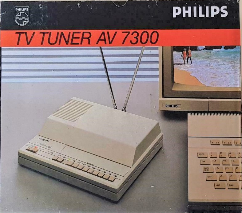
Box of the Philips AV7300 tuner box, which should be put between an MSX computer and a regular monitor.
|
Circuit diagram of the Philips AV7300 MultiMedia TV tuner, with the main functions highlighted. It was based on the Philips System4 (K40) CTV chassis IF. Note the use of a VST tuner and the twelve analogue channel pre-settings, and the use of discrete IF filtering, not yet based on a SAW filter.
A 1992 state-of-the art PC of IBM, the PS/2 Multimedia Model 75 based on the Intel X486 processor. As the name says, around this time multimedia functions started to be added to the basic PC. [Computinghistory.org.uk]
A typical view inside a 486-compatible PC with its ISA slots occupied by interface cards. A PC-TV card would be used in the same way.
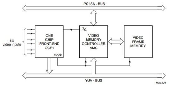
The main functions for the video processing on a PC-TV card using the SAA7110. One of the six inputs would be connected to front end module, the others could be regular video inputs from e.g. a VCR. [Philips Semiconductors SAA7110 Data Sheet]
|
Displaying TV broadcast content on a PC is technically quite different from watching it on a classical TV or, like in the case of the AV7300, on a standard analogue input monitor. To start, PCs are essentially operating in the digital domain, and any external analogue source requires digitization and formatting to make it compatible with the internal PC data structure. (Around the early 1990s most PCs were still 16-bit based, with the 486 cores being able to handle 32 bits too). For this interfacing IBM, when inventing the PC, had made the brilliant decision to accommodate every PC with a number of standardized ISA (Industry Standard Architecture) 8 or 16-bit interface slots. These slots were used for all external interfacing functions: video capture and accelerators, sound capture and play back (the famous Sound Blaster cards), networking interfaces and then also the TV reception card. By the mid 1990s the ISA slots were increasingly replaced by the Peripheral Component Interface (PCI), which was of the same concept but for 32 and later 64-bit inter-connections. In order to make the RF TV channel picture displayable on the PC monitor, multiple steps were required: RF-to-IF conversion (a tuner), IF demodulation, signal conditioning, analogue-to-digital conversion, luminance (UV) and chrominance (YUV) extraction, correction and filtering. The first two functions were performed by a front end, the remainder by video processing ICs like the Philips Semiconductors SAA7110 "One-Chip Frontend" OCF1, Brooktree and ATI Rage Theatre ICs. Because the video output was by definition not synchronized with the PC clock, and because PC monitors don't use interlaced but progressive scanning, the digital UV and YUV signals were written into a full frame picture memory. A Video Memory Controller finally read the memory driven by requests from the PC OS and put the signals on the ISA or PCI bus.
The advantage of this architecture was that the video processor IC required a CVBS video signal, exactly the output provided by the AV7300 tuner module as well as the typical FQ800, FS900 or FQ900 TV front ends already presented earlier. So that's how the Philips BU Tuners entered the what was called the "Multimedia" arena. 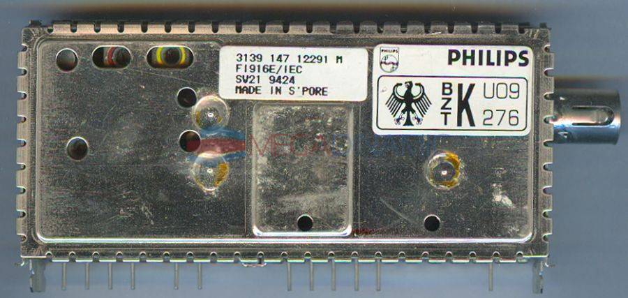
The Philips FI916E/IEC, the very first multimedia frontend, using inter-carrier IF.
|
At least in the beginning the PC-TV application was much simpler than the classical TV: single standard, CVBS video, mono sound and no extreme performance requirements. The BU Tuners, desperately looking for some profitable front end business, was thus quick to modify the most recent FS900 into the FI900. It still used the UV916E/UV936E tuners in combination with the Sanyo LA7570, but now with the IF IC in the inter-carrier mode, thus saving the sound SAW filter. With some of these prototypes two application engineers were sent to Taiwan in 1992, to co-operate with the many PC card manufacturers there. Two design wins were obtained with mainly the FI936 for US cards. Because the 900 was not available in horizontal mounting it required a large cut-out in the card, with the FI900 pins soldered flat on the board. Even more surprising, there was at least one design of a PC-TV card using the very large FQ900-Mk1!
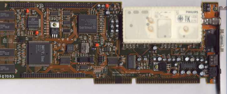
The Philips FI916E on an Aztech Video Galaxy Gamma 16-bit ISA-card. Note the cut-out of the PCB around the tuner to allow horizontal mounting. [BTTV Gallery]
|
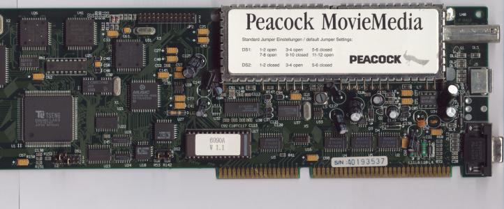
The Philips FQ916ME/L front end on the Peacock MovieMedia ET4000 ISA PC-card. This is the only known use of this front end family outside the TV. [BTTV Gallery]
|
|
It was obvious that the 900 family of front ends was too big for the PC-card application, and a smaller and thinner version was urgently needed. This became the FI1200, based on the UV1200 tuner and the TDA9800 IF-IC. The main characteristics were:
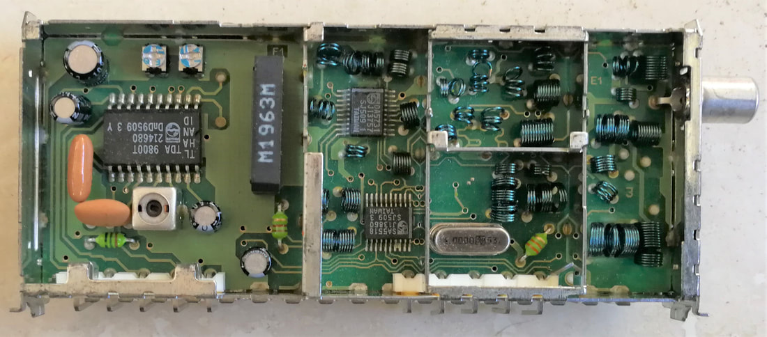
Top view of the Philips FI1236/HM/PH for NTSC. All three IC's, two SSOPs in the tuner section and the SO20 IF IC, are on this side, leaving the A-side entirely to SMDs. [Johan Bos collection]
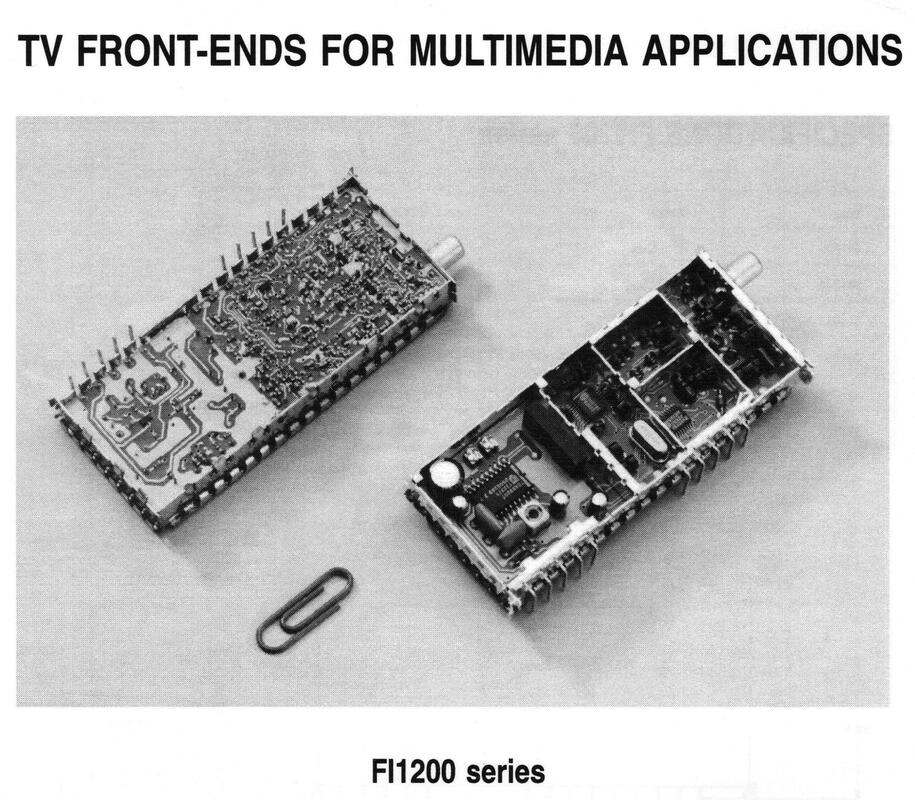
Publicity picture of the Philips FI1200 family from the first product-specific leaflet after stopping of the Data Books.
|
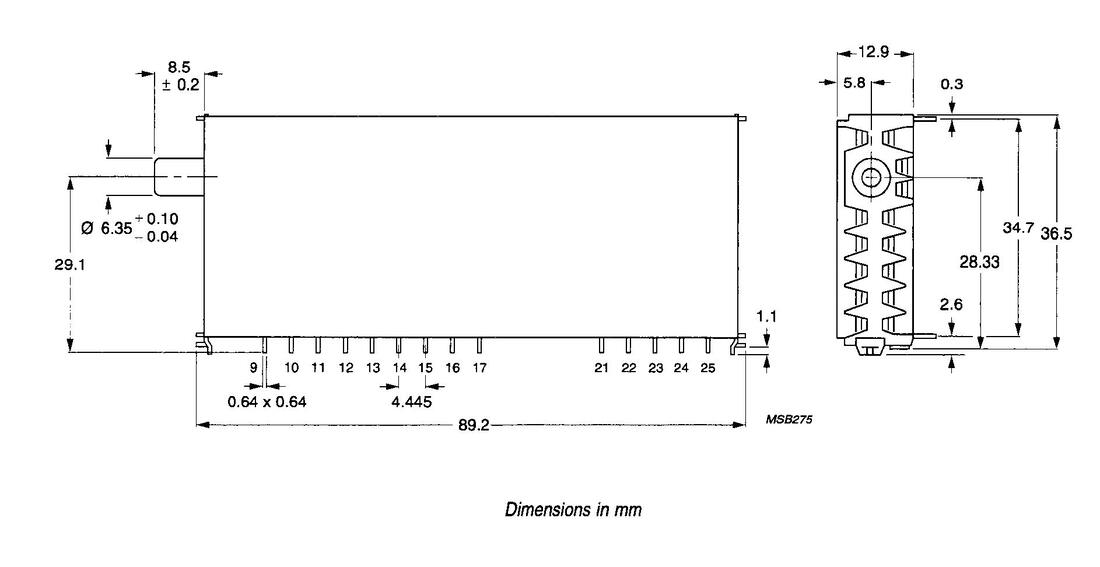
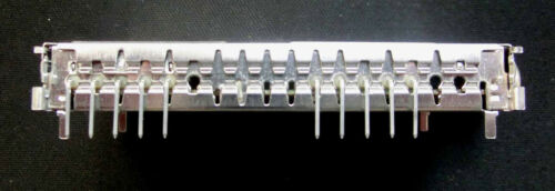
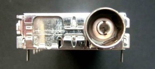
The Philips FI1200 PC-TV front ends. Top: mechanical drawing; centre: side picture showing the horizontal mounting; bottom: front view horizontal mounting.
The FI1200 was launched in 1994 and turned out to be the product the market was waiting for. The first products were quickly adopted by a number of US and Taiwanese PC Card makers, including big players like ATI (which would eventually become the biggest customer), Hauppage and Apple for its Macs. Also Philips brought out the PCA20 TV-capture card. The main runners were the European B/G (FI1216) and US M/N (FI1236) products, but every company trying to sell in the wider European region bumped into the same issues that had encountered the classical TV players: standard diversity. It was obvious that a multi-version was necessary, which became the FI1216MF Multi-France, covering B/G and L/L'. For the positive video modulation it switched to the multi-standard TDA9802 and for the AM sound demodulation the TDA9830 was added, just like the FQ900-Mk1. Apple Computers was the main customer for this model, which sold 600k pieces in 1996 already. With its broad family covering all standards Philips quickly captured the emerging PC-TV card leading position: 100k pieces of the 120k market in 1994 (80% market share), 450k of the 550k market in 1995 (85% market share).
|
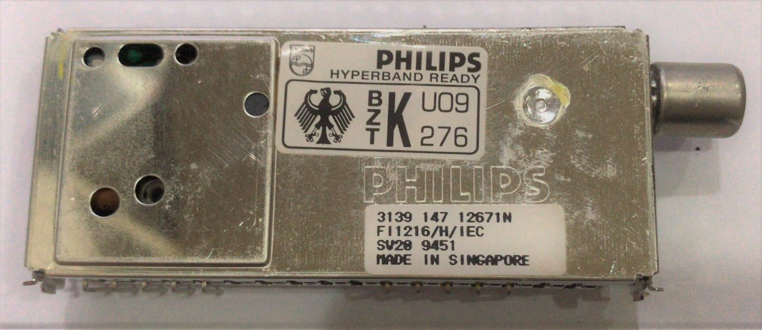
The Philips FI1216/hm/IEC. Especially the European types carried an Amtsblatt sticker to highlight the approbation approval.
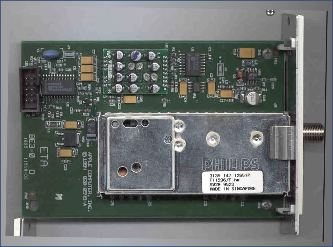
The Philips FI1236 on the Apple PowerMac Video capture card. Note that this card does not contain the video processor. [idem]
|
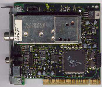
The same
Philips FI1216/hm/IEC, now on the Videologic Captivator card. This is an early 5V PCI card. Note the Brooktree video processor IC. [All card pictures from BTTV Gallery on homer.com.au]
|
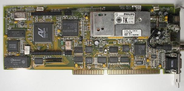
Again a FI1216/hm/IEC, this time on the Philips PCA20 card. This is clearly a first generation ISA card, using the Philips SAA7110 and an AverMedia IC. [idem]
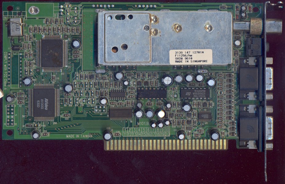
The Philips FI1256 for D/K standards and thus probably this ISA card is for Eastern Europe and Russia. [idem]
|
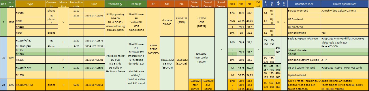
Overview of the first generations multi-media TV frontends for PC-TV cards, the FI900 and FI1200 families.
FI1200-Mk2 and FM1200 with FM radio, 1996
Quite soon after its introduction it turned out that the PC-TV multi-media market was much different from the classical TV consumer electronics market, despite the fact that conceptually the FQ900 for TV and FI1200 for PC-TV were functionally very similar. Most importantly, in contrast to the TV world the PC card makers didn't pretend they knew more or better about tuners and IF applications than the tner makers. So whereas a never-ending discussion about tuners versus frontends in the TV worrld, for the PC customers the front end (tuner plus IF) was of undisputed functionality. Even stronger, everything that could be done to further simplify the application was highly appreciated. The most urgent request in this respect was to get rid of the 33V varicap supply voltage, since this was a totally non-standard voltage in the PC power supply infrastructure.
At the same time the PC-TV card segment quickly became a fighter market, when in 1995 both Samsung and Temic (the former Telefunken) introduced "Chinese copies" of the FI1200, using the same ICs and frame size. This put a lot of pressure on Philips to continue leading through innovation and avoid being dragged into a price war. Fortunately these trends were foreseen early enough, and co-development with Philips Semiconductors had started on two major functional innovations. This became the FI1200-Mk2.
At the same time the PC-TV card segment quickly became a fighter market, when in 1995 both Samsung and Temic (the former Telefunken) introduced "Chinese copies" of the FI1200, using the same ICs and frame size. This put a lot of pressure on Philips to continue leading through innovation and avoid being dragged into a price war. Fortunately these trends were foreseen early enough, and co-development with Philips Semiconductors had started on two major functional innovations. This became the FI1200-Mk2.
|
Although the Mk2 re-used the 1200-Mk1 frame and from the outside looked identical, internally it had quite some changes:
|
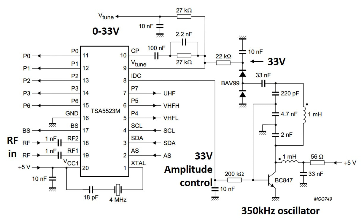
The application around the TSA5523 PLL IC to generate a 33V varicap bias voltage from a 5V supply. [Philips Semiconductors TSA5523 Data Sheet]
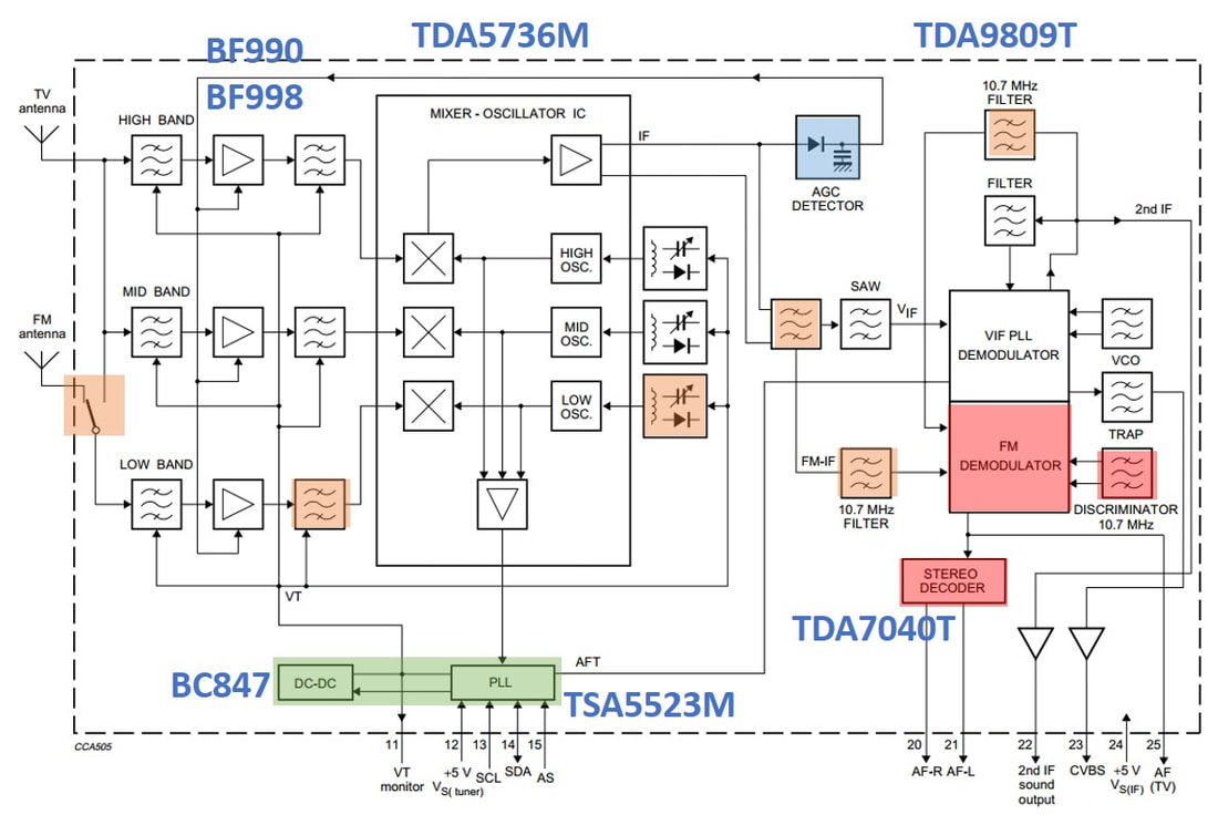
Block diagram and application of the Philips TDA9809 combined TV and FM radio demodulator. The functions added to the previous FI1200-Mk1 generation are the DC/DC-converter (green) and the wideband-AGC (blue). Orange blocks belong to the FM-radio functionality of the FR1200, while the red blocks are added in the FM1200. [Philips Semiconductors TDA9809 Data Sheet]
From 1992 Philips Components discontinued its famous series of Data Books, including those of tuners. The books were replaced by much condensed A4-size 2-page product leaflets, where the FM1200 was one of the first.
|
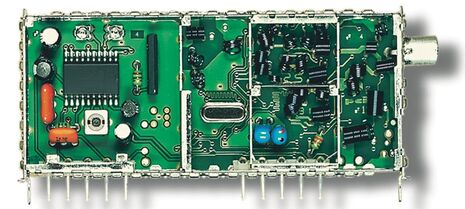
Top (B-side) view of the Philips FI1216-Mk2 (phono connector, vertical mounting) for PAL B/G. This side of the PCB only carries the TDA9800 IF IC. [via Darko Jancin]
|
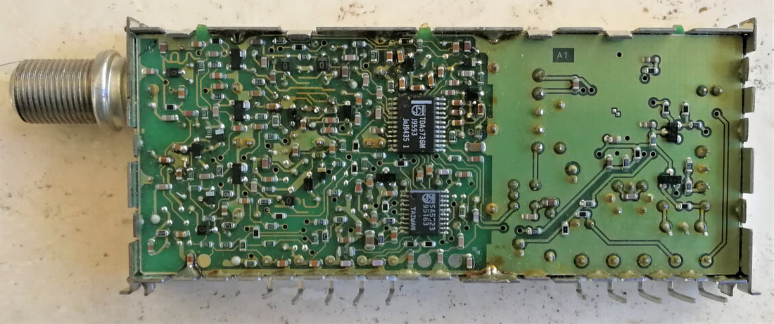
Bottom (A-side) of the Philips FI1236-Mk2/HM/F (F-connector, horizontal mounting) for NTSC. In contrast to the larger FQ900 front ends the tuner and IF are on a single PCB. [Johan Bos collection]
|
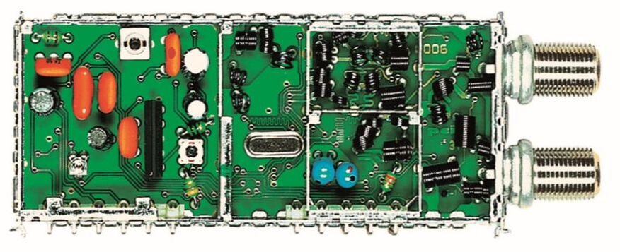
Top view of the Philips FM1236/HM/F for NTSC and FM radio. No more IC's on this B-side to make room for the additional radio-related filters. [via Darko Jancin]
|
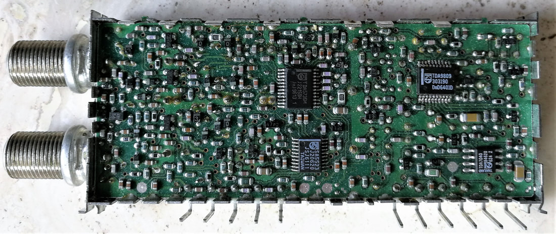
Bottom (SMD) side of the FM1236/HM/F, showing all four ICs. The IF IC is now also an SSOP package. [Ronald Dekker collection]
|
As to the technology, that essentially didn't change compared to the Mk1: the Philips 1200 frame and double-sided reflow soldering. The FI1200 had its tuner ICs (TDA5736 MO and TSA5523 PLL) now moved to the SMD A-side but kept the IF IC in SO-package on the B-side. The FR1200 and FM1200, requiring more space for the radio filters, had all ICs on the A-side.
The Mk2 family immediately had a very good market reception, the radio adding nice functionality while the internal DC/DC converter, which was marketed as "the only true 5V tuner", was highly appreciated by the card designers. The internal wideband AGC gave clearly better performance in case of strong adjacent channels. However, the road to success is a bumpy ride and the BU was confronted with a serious application issue, especially with one of the main customers and market leader ATI and their Radeon All-in-Wonder PC-TV cards. Around this time typical PC clock frequencies for the new 486 and Pentium processors were in the 100-200MHz range, or in other words right in the middle of the VHF TV band. Under normal conditions with a PC and TV set standing some distance apart this was no issue, but having a TV tuner inside the PC on a plug-in card on the main board was a different situation. ATI cards thus experienced visible picture disturbance for certain channels, essentially due to RF radiation leaking through the slots in the FI1200 frame (so-called ingress). Fortunately the Samsung and Temic front ends experienced the same problem. The only solution to it was wrapping the front part of the module with metallized tape and solder it close to the RF connectors. A costly solution, requiring a lot of manual operation.
Other than that the Mk2 family was a big success. The FI1200-Mk2 was launched in 1996, the FR1200 in 1997 and the FM1200 in 1998. With all versions the FI/FR/FM1200-Mk2 family included 27 different type numbers, including a first real Japanese FI1286. The number of card makers using the Mk2 family rapidly increased, with the FI/FR/FM1216 and FI/FM1236 as the high volume runners. With the Mk2 family Philips had clearly established itself as the benchmark for this product segment.
The Philips FI1216-Mk2/PH/HM on an early ATI Rage Pro Turbo PCI-card. The ATI Rage Turbo video processor IC is visible below the front end. [VGA Museum]
|
Another big customer, Hauppage. Here the Ireland-UK version using the FI1246-Mk2/IEC/HM. [BTTV.com]
|
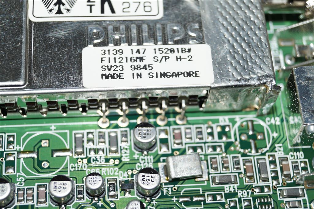
Close up of a wrapped FI1216S/PH-2 for ATI. Some of the wrapped versions obtained an S in the type name.
|
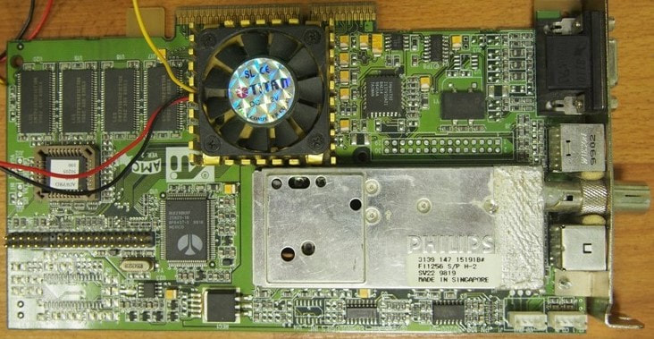
The Philips FI1256/PH-Mk2 on an ATI Radeon 1650 card. Note the front section of the module being wrapped in metallic tape.
|
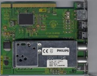
A Philips FM1216/IH TV-radio front end on a Philips Proteus PCI card. This card uses the SAA7134 multi-standard decoder for analogue and digital TV. [BTTV.com]
|
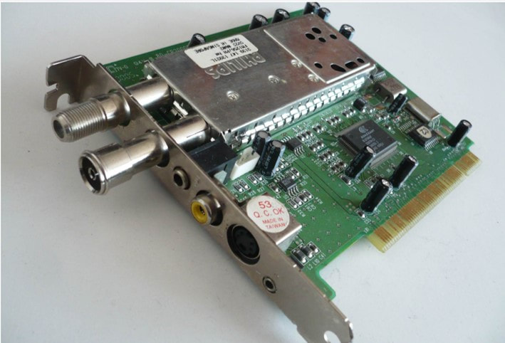
A typical PCI TV-card for, in this case, the FM1256/PH-2. The two RF connectors with their attached extensions are clearly visible.
|
The last addition to the 1200-Mk2 family was the FQ1216ME, the Q indicating the higher quality Quasi Split Sound concept. [The QSS concept was earlier used in the FQ800 and FQ900 TV frontends. For details on the concept see those sections.] The QSS demodulation obviously required a different IC, which was the TDA9818, able to apply IF video and QSS sound demodulation on both negative modulation schemes (B/G, I, D/K) and positive modulation (L/L' for France). Although in the meantime the next generation Alignment Free IF ICs (AFRIC) were in development, marketing did not want to wait for them and it was decided to keep the first FQ1200 in the Mk2 technology. Especially the longer 89mm frame was essential to accommodate all big discrete components (2 SAW filters, 3 Toko trafos, 1 potmeter and two elcos). The FQ1200 was released in 1999 only in the FQ1216ME Multi-Europe version, covering standards B/G, I, D/K and L/L' and was immediately a success. This model would become and stay the main runner of the multi-media frontends throughout the coming three generations.
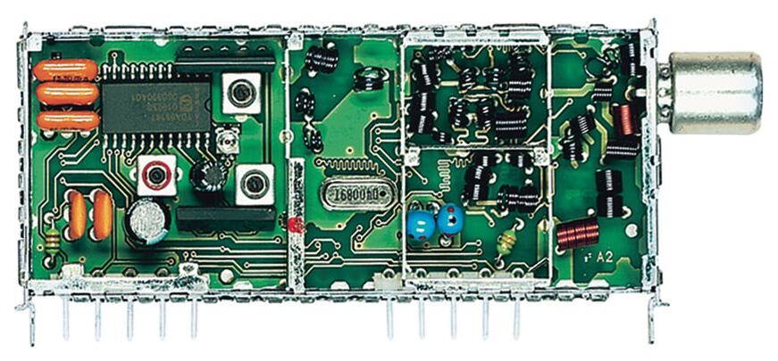
B-side view of the opened FQ1216ME/IH, the last model of the Mk2 family. Note the TDA9818T IF-IC. [Darko Jancin]
|
The FQ1216ME/PH on an ATI Radeon256 PCI-card. [VGA-museum.cz]
|
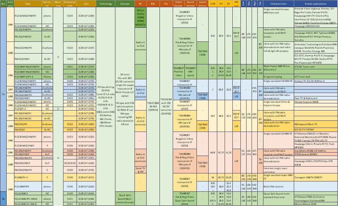
Overview of the known models of the Philips FI1200-Mk2, FR1200, FM1200 and FQ1200 multi-media front end family. It introduced FM radio, multi-Europe versions and at the end Quasi Split Sound. Note the large diversity of customers, mostly PCI-card manufacturers.
Philips organisation, 1990-2000
How was Philips doing in general during this time? Not so good. As we've seen in the previous chapter, Jan Timmer became the new president in 1991 amid an existential crisis of the company after eight years of internal fighting and a lack of overall strategy under the presidents Dekker and van der Klugt. When Timmer took over the company was virtually bankrupt, with huge debts and very thin profits. He launched Operation Centurion, essentially a major clean-up of the company that lead to the closing or selling-off of many businesses and factories. A non-exhaustive list of the most important disinvestments:
|

Jan Timmer, Philips president from 1991 to 1997. [Eindhovens Dagblad]
|

The Breitner-tower, the new Philips headquarters building in Amsterdam along the River Amstel.

In 1993 the company slogan "Philips invents for you" was launched, although not used consistently.
|
The only positive counter-move in this context was the creation, making use of the Asia crisis, of the JV with LG for the production of LCD TV screens. By the end of the decade the company had reduced to five Product Divisions: Consumer Electronics (CE), Semiconductors, Components, Medical Systems and Lighting. In the meantime the name was changed, in 1994, into from Philips Gloeilampenfabrieken NV to Philips Electronics NV. The fact that it became Royal Philips Electronics NV in 1997 was nice but other than that insignificant. Timmer not only relentlessly rationalized the organization, but also launched and prioritized 20 so-called "presidential projects" that were supposed to be no-fail projects and investments into new technologies. It included such new products as CD-interactive, DVD, DCC digital audio cassette and LoCos displays, which were targeted to give Philips again the lead in consumer electronics. Although the company actively launched and played in most of these technologies, it was no longer capable to drive such costly innovations on its own, and in most new standards they remained a modest player. Furthermore, the proprietary standards like CDi and DCC failed miserably, despite Timmer's support. In 1996 Timmer was forced to resign and replaced by Cor Boonstra, formerly Sarah Lee/Douwe Egberts coffee. With him Philips finally got a president with a complete lack of understanding of technology, electronics and the typical markets the company played in. In his pre-presidential period Boonstra was responsible for inventing the new "Let's make things better" company slogan, which at least by the technical community within Philips was never understood and essentially interpreted as an insult to their work. Boonstra's biggest strategic decision was the utterly useless move of the Philips headquarters from Eindhoven to Amsterdam, probably to make sure there was indeed no link between the technical basis of the company and management. Boonstra survived till 2001 without making any positive strategic move of importance. [This last sentence is undoubtedly contested by the financial experts, who were harassing Philips with their traditional "conglomerate penalty" on the share price. They forced the Philips management, without a strategy of its own, to sell off most of the businesses as shown above, making huge profits on the M&A fees. Remember this was the time of vulture capitalism!]
|
Philips TV business, 1990-2000
|
Consumer Electronics, since 1993 under Henk Bodt, and especially TV, which was together with Audio and VCR now called Sound & Vision under Tollenaar, had a hard time, with Japanese competition at its strongest and Korean companies Samsung and Lucky Goldstar (LG) coming up rapidly. (Although there was a number of Chinese set makers towards the end of the decade, they were only operating locally in China in what were considered very low end markets). As already explained in the previous chapter, the TV organization had finally been integrated, with pre-development in Eindhoven TV-Lab (some 200 people), and set development in Knoxville (Tennessee, US market, 200 people), Brugge (Belgium, high-end, 120), Dreux (France, mid-end, 120), Monza (Italy, low-end, 35 people) and Singapore (global low-end, 135 people). A new software centre was opened in Bangalore (India) while the development of digital systems (Set Top Boxes) was concentrated in Suresnes (France, some 70 people) and Eindhoven.
The product segmentation of the Business Group TV remained three-tier: high-, mid- and low-end. In 1991 three new platforms were launched for these three segments: the high-end Feature Line (FL1 and FL2, using the FQ800 front ends), the mid-end GR1 (and upgrades GR2 to GR6 in the following years) and low-end Anubis chassis, both using the UV900. Note that apart from the FQ800 and US-sets that used PLL types, all mid and low sets still used VST tuners until 1995! The former Overseas organization was an exception, using PLL tuners throughout its last G8 and G88 chassis versions. However, from 1993 onwards Overseas no longer existed and was merged into the new organization, for example the Anubis-S (launched 1994) served the typical Overseas markets. The TV organization remained very conservative on other concepts too, for example only in 1993 a first Latam Anubis version introduced the Philips semiconductors 1-chip IC. Volumes were very clearly centred on the low end (some 8Mio sets/year), with mid end 4Mio and high-end 400.000 only. In this period, the early nineties, BGTV sales were still growing modestly, not bad given the strong competition and persistent yearly price erosion of some 5-10%. But especially the value of the high-end sets was improving due to the new features like 100Hz, digital scan, picture-in-picture and NICAM digital sound, while the low-end segment benefited from the rapidly expanding markets in growth areas like Asia, India and Latin America. In contrast the US TV business remained a large (4Mio sets per year) problem. The Magnavox brand had degraded to the level of one of the worst low end players in a highly competitive US market, essentially only selling 13", 14" and a few 21" sets, with retail prices for a 13" set already at 95$ and 14" approaching that boundary soon. Sales were mainly through wholesale dealers like Walmart, which provided volumes (Walmart alone 1Mio pieces/year) but at very bad margins. From 1992 to 1995 the BGTV sales nevertheless increased from 5,8 to 6,4BioHfl, making a very modest 140Mio profit (2%). In 1996 therefore a next round of reductions was announcement: the Monza factory was closed and Dreux development stopped, which meant that all low- and mid-end developments were now in Singapore and high-end in Brugge. Knoxville Development still survived for the US low-end, but the Greenville fab was closed and sold in 1997, as was the South Africa Martindale fab. Another major reduction took place in iR3 : VCR production in Wien and Nürnberg was ended, moving to Székesfehérvár in Hungary. |
The Philips high end chassis launched in 1991: FL1.0. This is the 25" 25PV7505 100Hz IDTV. [Marcels TV Museum]
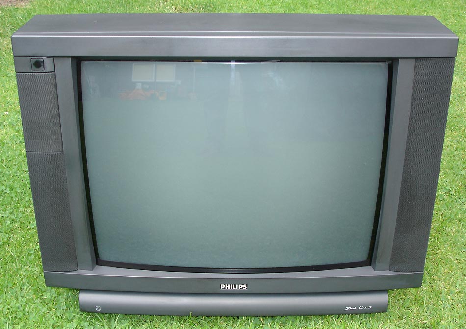
The 1992 Philips mid-end chassis GR2.2, the 25" 25ST2761. [Marcels TV Museum]
The 1991 Philips low-end chassis: Anubis-A. This is the 14" 14PT135A. [Obsolete Telley]
|
Philips TV coding convention, 1990
In 1990 Philips changed its TV coding scheme again, but this time with a fundamental change. Where so far the two letters and first number in the code indicated the chassis, from now on they indicated the set category. Which meant that "identically" featured sets from successive chassis used the same code. From now on a code had the format 11CCX234, with 11 the screen size, CC the category, X the feature/luxury level and 234 the specific set identifier. This scheme would be in use for 17 years, until 2007. As one example the series of 25" mid end (PT4) sets was:
- 25PT4401 MD1.1
- 25PT4403 L6.2
- 25PT440A GR2.2
- 25PT4428 L7.3A
- 25PT443A GR2.4
- 25PT4454 L6.3
- 25PT4455 L9.1
- 25PT4457 L01.1
|
The next generation TV chassis, planned for launch in 1995, were the high-end Global Feature Line (GFL, developed in Brugge and using initially the FM900, later the FQ900-Mk2), the mid-end Mid1 and Mid2 (the first covering the smaller screen sizes, Mid2 up to 33", both developed in Dreux and using the UV916S) and the low-end L6 (an Eindhoven-Singapore-Monza extension of the Anubis-A5, still using the UV900 VST tuners). As explained earlier in the FQ900-Mk2 section, when defined in 1993 the GFL was still supposed to support D2MAC and be prepared for HDMAC and PAL+ (16:9 wide screen). The MAC requirements were dropped in 1994, PAL+ becoming the new wide screen driver. Parallel to the GFL the FL2G was the "overseas" extension of the Feature Line FL2 chassis, using the FV916MG multi-global video-only front end. In general the demarcation between Mid and GFL was vague, so some Mid2 models could be considered as high-end, while the simple GFL1 models were positioned as standard segment. Especially for the Asia market many activities were shifted there. During the early nineties the Singapore TV Fab grew a substantial Development Lab, with many ex-pats from the rapidly shrinking Eindhoven and Dreux organizations. Around 1995 another TV factory was built in Suzhou, China, especially for the Chinese market. (Formally this was a JV with Peacock, because foreign companies were not allowed fully owned fabs in China. Samsung, Matsushita and Alps had similar JVs with local Chinese TV makers). The first and most important development in Singapore was the low-end L7 chassis, intended for the global market except the US. The L7 had very aggressive cost targets, with a total Bill-of-Material of 106USD of which 49USD for the picture tube. As we will see later there was only a few USD room for the tuner. One way to reduce cost across Sound & Vision was to start sourcing from other suppliers than the internal Philips organization., where the iR3 VCR group had taken the lead and was considered to be very successful in the eyes of management. As we have seen earlier, iR3 had been buying Alps modulators already since 1989. Dreux TV was the first to design in a low cost competitor tuner into the L6 chassis, an Orega equivalent of the UV915, but this failed Cenelec approbation and they had to return to the Philips tuner. With the 1997 L7 (8Mio sets/year), 1998 A8 (3,5Mio sets/year), 1999 L9 and 2000 A10 the TV group pushed aggressively for at least 30% external tuner supply. The high-end segment remained loyal a bit longer with the Mid-GFL (or MG, 1998) but by 2000 the EM chassis also used a large share of 3rd party tuners. After 2000 there were no more Philips TV chassis that exclusively used Philips tuners.
|
Example of a Philips Semiconductors reference design for a 1996 high-end CTV chassis. Note the two large video processing ICs (the OneChip cut in two, predecessors of the Hip and Hop) with the 100Hz feature box in between. Here was also the input from the 2nd PIP tuner. Upper left the tuner and PIP splitter PS1316. [Philips Semiconductors TV Reference Designs]
During the 1990s the consumer applications were by far the dominant segment within Philips Semiconductors, and the company maintained a leading position in the domain. Since its launch in 1990 the one-chip TV ICs had become a huge business success, growing from 1Mio ICs in 1991 to 48Mio in 1997 and 64Mio in 1999, which meant that in 50% of all TVs world-wide a 1-chip IC was used. At the time the 4th generation was in full production, using 0,8um BiMOS3. The 5th generation Ultimate One-Chip (UOC) was in development, which was a multi-chip package including both the 1-chip and the Painter Teletext IC as separate dies. The one-chips were developed in Nijmegen and Hamburg, the Painter in Southampton using 0,375um C75OTP (one-time programmable). For the high-end a one-chip was cut in two, the HIP (High-end Input Processor) and HOP (High end Output Processor). In between was the 100Hz digital feature box with A-to-D converter, the Falconic 100Hz IC and D-to-A converters. The Hip-Hop-Falconic solution was introduced in the 1998 MG-platform. For the mid-end the BOCMA (BiMOS One Chip Mid-end Architecture) came available towards the end of the decade, and would be used extensively in LCD TVs. Throughout the 1990s Philips Semiconductors remained the by far biggest supplier to the TV Group, delivering essentially all core ICs except the NICAM digital sound processor, which came from ITT. Overall Semiconductors was doing well, growing from 3Bio€ in 1996 to 6,5Bio€ in 2000.
Philips mobile phones, 1990-2001
|
While Philips was battling for survival in the classical consumer electronics domain (audio, TV, VCR, and optical recording (DVD)), the company tried to expand in new and potentially more profitable businesses. One of these was the emerging mobile phone. This had a complex organizational history. In 1983 Philips put most of its Philips Telecommunication Industries (PTI, HQ Hilversum in the Netherlands, where my mother worked from 1953-57) in a joint venture with AT&T (AT&T-Philips Telecommunication, APT) from which it withdrew in 1990. However, the German Philips Kommunications Industrie (PKI, Nürnberg, Germany and Kopenhagen, Denmark), the French Télécommunications Radioélectriques et Téléphoniques (TRT, Paris) and UK Philips Mobile Radio (Cambridge) were kept out of the JV, mostly due to strong resistance of the local country organizations. These three were the centres where amongst others mobile radios for the car were developed, initially based on analogue standards, but by the end of the 1980s the new digital Europe-wide Global System for Mobile Communications (GSM) was standardized, and in 1991 a first call was made on a Finnish system. Initial GSM phones for the car were huge, roughly the size of a shoe box; mobile but not portable! However, during the early 1990s aggressive miniaturization made it possible to make the first portable (but still sizeable) handheld mobile phones. The main driver within Philips of this new application was PKI in Nürnberg, although still as a side activity of the telephone switches and communication equipment. In 1993 PKI made a big loss of some 390MioDM, and in 1995 it was sold to AT&T, later Lucent. As with the previous JV, part of the business was kept within Philips: the mobile phone development. However, the bulk of development and production was transferred to the former Schneider TV factory in Le Mans, France, which had migrated via digital terminals to cordless phones already. In 1996 also the Cambridge Private Mobile Radio, one of the old and famous Mullard activities, was sold, and Le Mans became the headquarter of Philips Mobile Phones (PMP), later Philips Consumer Communications (PCC).
Because it seems ages ago, it is easily forgotten that during the emergence of the first and second generations of GSM Philips was one of the leaders, in Europe only second to Nokia and after Nokia and Motorola the worlds number three! It made very trendy and compact phones like the Fizz and the Savvy. However, the PCC people, and especially the freshly flown-in American managers, were notorious for deliberately not following the Philips Product Creation Process (PCP) which focused on reliability and quality of the product, ("we are different from the rest of Philips and don't use Philips processes" was their motto) and the otherwise very good Spark phone from 1998 experienced catastrophic failures when, due to sloppy and apparently untested mechanical design, the battery pack fell out during use. With a field call rate of more then 150% it destroyed the quality image of the Philips phones, from which the company never recovered. On top of that, in 1997 a disastrous 60%-40% joint venture was made with Lucent Technologies (the former AT&T, with no position whatsoever in mobile phones), where the first action was to construct a huge new headquarter building in the US. After 500Mio$ losses during the first year Philips stepped out already one year later, end of 1998. These two disasters made that the Philips position in mobile phones rapidly deteriorated, reducing to an 8% market share in GSM Europe and 3% globally. In 1999 PCC sold around 8,5Mio GSM sets in the global GSM market of roughly 250Mio sets, while the total global mobile market was 440Mio sets. In 2001 the company cut its losses and stepped out of the mobile business, with a 1250 people reduction in the Le Mans factory. The Chinese company CEC would continue so sell Philips-branded mobile phones for at least another decade. In the following it will be explained what the BU Tuners role had been in this story. |
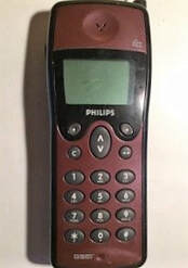
The 1996 Philips GSM phone "Fizz", at least as robust as its Nokia 6310 competitor.
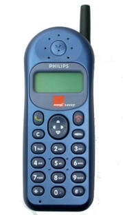
The 1998 Philips "Savvy", another successful model. [Pocket Line.com]
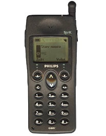
The 1998 Philips Spark mobile phone, the one that had the infamous battery pack quality issue. [GSMversus]
|
Philips Tuner business and organisation, 1990-2000
Since 1982 the Tuner business was lead by Johan Visscher, who came from the VCR organization after the V2000 was stopped. Initially he still reported to Mr Hoevenaars, head of the HIG Video group Samengestelde Componenten (Assemblies). From 1985 onwards, when the HIG Video was integrated into the new Product Division Consumer Electronics, the now Business Unit (BU) Tuners reported to the BGTV manager Alphons Dassen, just like the much larger BU TV and the much smaller BU Remote Control (headquartered in Leuven, Belgium). This was a strategically important re-positioning of tuners, recognizing the much higher complexity and business potential compared to the Samengestelde Componenten organization. It was Johan Visscher who would, in a period of ten years, streamline and integrate the Tuner organization. As explained earlier, step by step the old, often regional, tuner production facilities were closed: Sant'Angelo Lodigiano (south of Milano, Italy, 1982), Barcelona (Spain, 1984), Dunfermline (Scotland, UK, 1987) and finally Rambouillet (France, 1990). Manaus, up the River Amazone in Brazil, remained the only exotic manufacturing site not under the full control of the BU.

The Dunfermline, Scotland, UK, tuner factory. Next to tuners it also produced PCB cards. Tuner production stopped 1987 and in 1993 the fab was sold to the US PCB manufacturer Solectron. [Dunfermline site]
|
The Lamperas-Z factory in Barcelona, producing lamps and later TV sets. Tuner production was a smaller activity between 1980 and 1984.
|
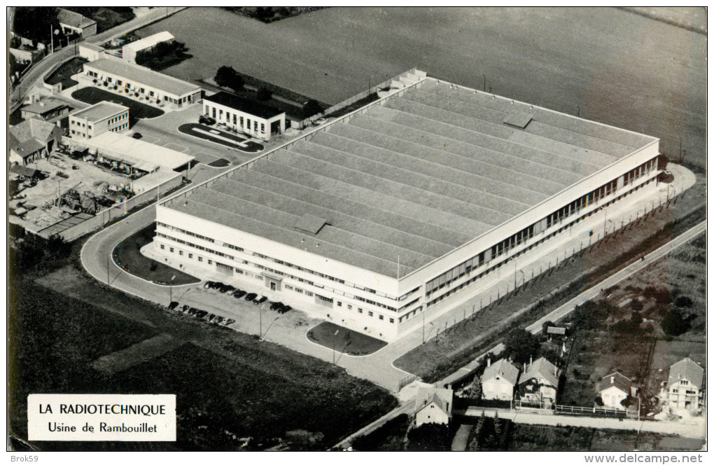
Rambouillet, France, tuner factory since the mid 1950s. Later also Car Radios, which remained the primary activity after Tuner production ended 1990.
|
Manufacturing was now concentrated in Singapore (8Mio products) and Wesel (till 1990) and Krefeld (5Mio products). This was, however, only a brief moment of stability, because driven by the price erosion in the consumer electronics world, a steady shift to cheaper production sites followed. Also Singapore, producing already close to 2/3rd of the BU volumes by 1990, was becoming rapidly too expensive, and in 1991 construction started of the big new factory on the island of Batam, Indonesia, a 40min ferry ride across the Singapore Straits. (Although located on Indonesian soil, the industrial park there was tax and logistics-wise an extension of Singapore, to allow minimal disturbance when transferring goods to and from the island). The Batam fab was almost managed as an extension of the Singapore organisation, which was also reflected in the production code which remained SV. (Only after a few years the notice "Made in Indonesia" was added). The shift to Batam went with a major restructuring in Krefeld, where production was reduced to non-standard products only: the high-end UV916H and M tuners, the FQ900 TV front ends, the first SF900 and 1200 satellite front ends and LNB microwave modules. In practice this meant that only 4Mio out of the total 13Mio products were produced in Europe. Singapore also steadily shrank in size with the opening of Batam, reducing it to just one production floor. It produced roughly the same number of 5Mio products as Krefeld, while 5,5Mio products, initially only UV900 tuners, came from Batam by 1993. Batam continued to grow and remained the biggest factory of the BU, reaching a volume of around 16Mio units by the end of the century.
The first of the three BU Tuner production sites by 1993: Krefeld. The yellow ball house for EMC measurements is visible in the back.
|
The Philips Tao Payoh complex in Singapore. From front left clockwards: TP2 (TV factory), TP4 (Semiconductors), TP3 (Tuners), TP1 (Audio).
|
The factory with the biggest volume: Batam, Indonesia. Interestingly, it was located directly adjacent the Thomson tuner factory.
|
|
A next step was the Krefeld volume production being moved to a new tuner fab in Kwidzyn, Poland, some 150km south of Gdansk and near the already operating BGTV factory in the same town. Kwidzyn started in 1995 with UV900 production, but gradually took over the SF1200 and later the European UV1300. It was essential for having products with Euro-content. At the same time, while production in Manaus, Brazil, was ramped down, a tuner line was opened in the new Philips TV factory in Suzhou, China. Again it started with UV900, later also the UV1300. By the end of the decade, around 85% of TV tuner volumes were now coming from the Asian production lines.
|
Location of the Philips Tuner factory in Kwidzyn, Poland.
|
Locations of the Philips Tuner factories at Singapore Tao Payoh (red dot) and Batam (green).
|
By the end of the 1980s both the Philips TV business and Tuner business had reached a plateau, no longer growing in sales. In practise this meant a small growth in volumes and the mix (more expensive high end models versus cheap low end sets) compensated by the continues price erosion of some 7% per year. Tuner sales in the 1989-1991 period hovered around 12-13Mio pieces at 300MioHfl (150MioUSD) turnover and modest but solid profitability of some 8%. Profitability of the 3BioUSD BGTV business was much lower, usually 1-2%, so barely break even. Both were suffering from the same developments:
- the Philips market share was no longer growing, on the contrary, the presence in the growth market segments (mainly Asia) was very low. The global TV market share of Philips was stable at around 12%.
- TV as a basic function had reached a saturation level, with a very high percentage of global households now having a TV set. At this time the global CTV market was around 110Mio sets/year, with an additional 50Mio VCRs. Growth in both markets was only a few percent per year, and price pressure was consequently high.
- Continuous cost reduction to counter the price erosion in a market with no volume growth. This was done by the measures that have been discussed already many times so far: size reduction (fewer materials), cheaper components (the continuous battle with Philips Semiconductors and 2nd source suppliers) and labour cost reduction by closing the expensive small scale European factories first, and then moving to Singapore/Batam (first) and Eastern Europe and China (next).
- Addressing new market segments for RF modules, preferably re-using the tuner technology platforms. First examples were TV front ends, satellite front ends, multimedia front ends and tuner-modulators, first generations of which have already been discussed. Other RF modules, requiring more dedicated technology platforms, were LNB microwave modules and telephone modules. A hybrid segment, since based on tuner technologies but addressing entirely new sets of customers, was digital television for both satellite, cable and terrestrial reception.
- The most daring and risky strategy was to obtain more access to the tuner markets that were not using the Philips pinning (essentially the entire Asian market), which were so far blocked for sales of Philips tuners. The strategy was to define, together with the main Japanese players, a new global World Standard Pinning (WSP). This will become one of the major discussion items during the entire 1990 decade. It will be discussed in detail in one of the following sections.
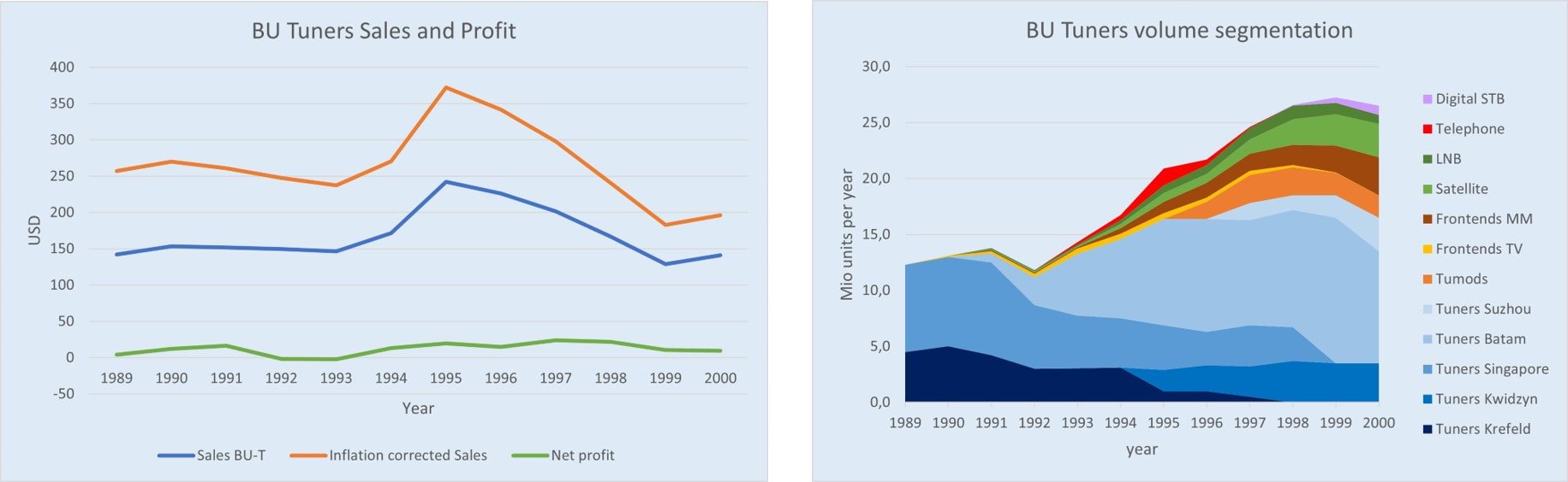
Philips BU Tuners sales and profitability (left) and portfolio build-up (right) for the decade 1989-2000. To put the sales in perspective I've added the (Dutch) inflation corrected sales number because during this period sales were reported in NL Guilders and inflation was often fairly high. However, the graph uses USD for better international reference. The USD/NLG exchange rate in these 12 years varied between 1,6 and 2,6 USD/NLG. The right graph shows volumes in Mio units. The volume transfers from Krefeld to Kwidzyn and Singapore to Batam are very visible. Here it should be remembered that most new non-tuner products had sales prices 2-4 times that of a standard tuner. So sales numbers were more balanced.
|
By 1990 Tuner Development consisted of three groups. At the BU headquarter, Eindhoven, the smallest group of 25 engineers was now part of the TV Front end Lab organization, located in the Strijp SFJ2 building. When Tuner Development went to building SFJ (first the 3rd floor, later the 2nd) in 1983 it had absorbed part of the TV IF Development, some 10 people, which developed the FS900 and FQ900 TV Front ends. Krefeld initially had the largest development group, but after a restructuring round in 1992 this had been reduced to around 30. By 1993 Krefeld and Eindhoven were under a single Development Manager. The Singapore Development Lab had grown over the last years to a stable 45 engineers, and would remain so for the remainder of the decade.
In 1993 Johan Visscher left the BU after 10 years, ironically at the moment the new businesses were finally kicking in. Because of his long tenure in the job he had become one of the old hands within BGTV, able to keep the desperate TV business at arms length from the BU. That changed with the new BU manager, Rob de Ridder, who essentially was a career man and did everything to avoid irritation on the side of his TV bosses. The results were immediately felt, when his first decision was, on the request of the TV Labs, to close all Eindhoven activities and move the BU to Krefeld. In the process some 15 engineers were lost to the BU, most of the IF engineers moving back to TV Labs. Krefeld now had a 45fte lab, just like Singapore. The more lasting effect of the BU management change was that from now on every price reduction request from TV was awarded, resulting in severe erosion of the internal Philips tuner sales (or more formally "internal transfer"). Also the BGTV external sourcing policy was officially accepted by the BU. The high level effects of these are already visible in above sales curves, but will be discussed in more detail in relation to the new WSP tuners. |
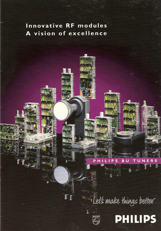
1995 Publicity picture of the BU Tuners product portfolio from the front cover of a multi-page leaflet. Tuners, front ends and LNB's are visible. Note the horrible new "Let's make things better" logo introduced that year.
|
With the much bigger influence of the internal Consumer Electronics politics independent growth into new applications now also became much less important. It was not that all new activities were stopped, but the priority was (again) on internal BGTV modules: as cheap as possible tuners and TV front ends. And the TV business was not willing to invest in non-TV products like satellite, mobile and microwave. Ironically the investments by the much more visionary Visscher started to pay off in the 1994 and 1995 financial results, with almost all new business segments contributing to an impressive sales increase from 150 to 250Mio$. Nevertheless no new segments were started after 1993, and the existing ones were forced to use only the available technologies. As a next step the BU stepped out of two segments: as already discussed BGTV and Tuners (to the mutual satisfaction) discontinued TV front ends, the FQ900-Mk2 being the last generation. The analogue CT1, AMPS and ETACS telephone modules were also brought to an end. There was a lot of discussion, in contrast, as to whether the BU would get involved in the new digital standards for cordless (DECT, the Digital European Cordless Telephone) and cellular (GSM). Although especially GSM was "hot" within the company and the BU manager did everything to get involved, in the end Nürnberg and Le Mans opted for the RF directly on PCB, simply because a BU Tuners module with the available technology would become to big. In hindsight they took the right decision, now that we know how quickly mobile phones shrank in size. The frustration at BU level about this failure at the same time created a mental block to any future activities related to wireless standards. For example a Singapore-developed first generation 802.11 WiFi module was never allowed to move to full development and production, the BU missing out on a market where modules were used for many years.
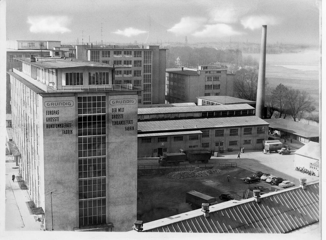
Grundig Werk 1 along the Kurgartenstrasse in Fuerth, the original main factory of the company where radios and the first TVs were produced. In 1994 it still contained a number of component activities: Stanztechnik (metal stamping), Oberflächentechnik (surface treatment), Wickeltechnik (wire wound components) and Tuner und Modulatorenbau (RF modules). [Rundfunkmuseum Fürth]
|
A last exploration driven by the internal Philips politics was Grundig. Philips, after having taken over majority ownership of Grundig in 1985 during the V2000 VCR period, was struggling what to do with it. The Philips approach would be to integrate it into the bigger Philips structure, a step effectively realised with the Grundig VCR activities into the iR3 joint venture, but the Grundig organization was strongly opposing this trend, trying to keep as much independence as possible. Integration discussions were therefore reduced to discussions on specific business level, and de Ridder was tasked to explore the integration of the two tuner activities. In February 1994 an exchange took place to investigate the opportunities. Grundig produced some 2,5Mio units TV tuners, 500k satellite frontends and 500k VCR splitter-modulators in Werk 1 in Fürth, the Grundig mother factory. Grundig tuners were size-wise similar to the UV800 and electrically compatible with the UV900 and based mainly on Siemens active components. A 1200-compatible smaller size family was in development. Most interestingly, Grundig had pushed automation to the extreme in its battle against price erosion and Asian labour cost, and produced its tuners according the Automatic Tuner Alignment (ATA) concept. The two steps that were most labour intensive in classical tuner manufacturing (air coil insertion and alignment) were thus 100% automated, with small plastic wedges opening the coils during alignment. An impressive achievement, but not an overall cost reduction due to their limited volumes. In contrast Grundig was still only using 0805 SMD components and did not have reflow soldering. Discussions touched on using Fürth for SF1200 production capacity, and de Ridder was even willing to exchange the Philips LNB business for the Grundig tuner share, but in the end no agreement was reached. (In 1997 Philips sold its Grundig share and stepped out completely, while Grundig was taken over by a consortium in 2000. Around that time they also stopped tuner production).
|
In the end no strategic steps were taken other than continued cost reduction in Europe and extension of Batam and Suzhou production. No new applications were added to those started already under Johan Visscher, and the focus of the management remained on the tuner. With dramatic results, because starting from 1996, driven by the WSP introduction, the tuner prices started to collapse at a speed of 20%/year that could not be compensated by increased sales of the new products. By 1998 the sales was back at the 1993 level and from then on lower. Tough times ahead for the BU Tuners!
Tuner Development and Product Creation Process (PCP)
|
At this point it is useful to have a brief look at the internal development process within the BU Tuners. In general, being a 100 year old company, by this time with 250.000 employees, Philips had a strong process culture, meaning that all "routine" processes were well standardized and described. This covered all areas: production, logistics, sales/order intake, finance and controlling and of course also development and engineering. During the 1980s a refreshed Product Creation and Realization Process (PCP/PRP) was rolled out across the Consumer Electronics organization. And the way this went within Philips it was owned by a central group that rigorously enforced and monitored implementation and adherence. In other words, not complying with the process was not an option. Being part of the Consumer Electronics organization, also the BU Tuners drove all its development and industrialization using the company PCP/PRP.
The PCP/PRP was a classical gated process, where a project could only proceed if the gate was approved. Standard management check lists were used to guarantee all relevant topics were covered during a gate meeting. Gate meetings were attended by the entire local factory management, thus covering all disciplines. Gate passing or not was not just dependent upon the development status of the product, but was also related to manufacturing , purchasing, projected production cost and sales outlook (volumes, timing, prices). Up to Design Release (DR) the development organization was the owner of the process and responsible for progress and planning of the gate meetings. At DR ownership was handed to Operations/Manufacturing. However, Operations was involved in the process from definition (Architecture Choice) while Development remained involved till at least Industrial Release (IR).
|
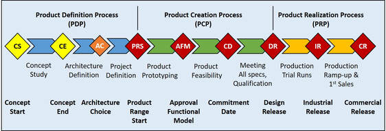
The official Philips CE gated PCP/PRP process. Diamonds show the mandatory milestones at which a gate review meeting took place. Red milestones were mandatory, the yellow ones were implemented locally within the BU Tuners.
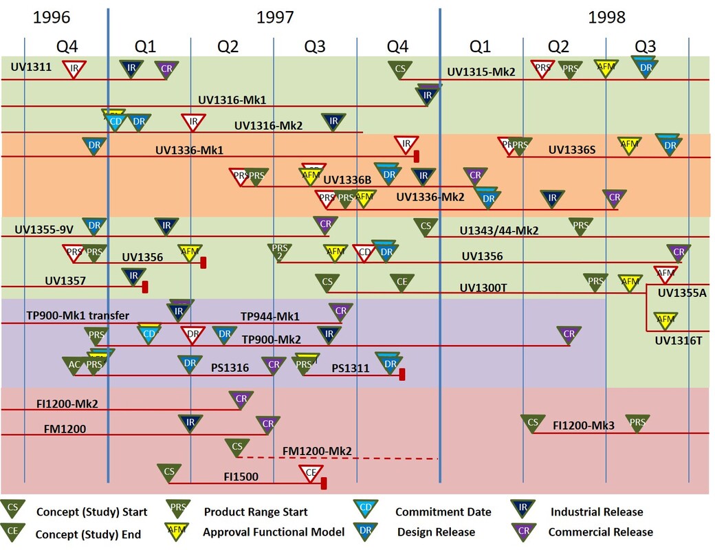
Overview of the development projects and their milestones as execute during my tenure as Tuner Development Manager in Singapore. 1997, with the UV1300-Mk2 roll-out, was a busy year with 44 gate review meetings for on average 10 running projects. White gates were not passed, a red block indicates projects stopped before completion. [Pieter Hooijmans collection]
|
Statistics of my 2 year in Singapore show the magnitude of these gate meetings: 72 in 24 months, of which 12 were not passed (16%), usually because of business uncertainty. Well running projects took 12 months from Concept Start to Industrial Release, but once the family technology was released this could be as short as 9 months.
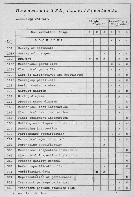
Overview of the documentation items that were required for a product to production. For more complex products like TVs the list was even longer, this was the sub set mandatory within BU Tuners.
|
The gate reviews were only the management decision points, at project level many more sub-processes were standardized and mostly implemented as mandatory way of working:
|
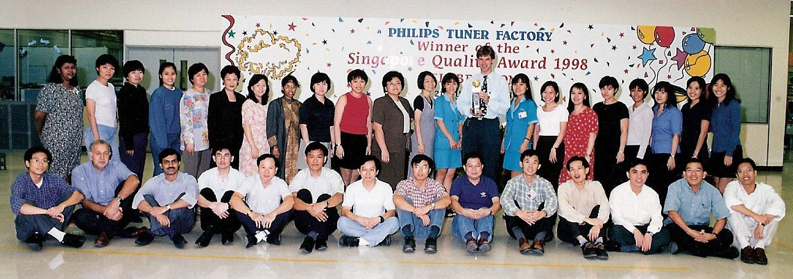
Official picture of the 1998 Singapore Tuner Development department, at the occasion of the Philips Tuner Factory receiving the Singapore Quality Award (SQA), which yours truly is proudly holding. The very structured way of working and R&D processes contributed substantially to winning the SQA. [Pieter Hooijmans collection]
Tuner factories and technology, 1985-2000
The first generations electronic tuners in the 1970s and 80s (the V6/U6, V7/U7, VD1/UD1, V300/U300 and ELC1000/2000) were essentially fully hand assembled, and in that sense not different from the earlier bulky tuners, apart from the form factor. With the UV400 started a trend towards much more automated assembly, driven by cost and size reduction. Tuner manufacturing was a complex multi-step process, which was, after the introduction in 1985 with the UV600, split into three phases:
- Production 1 (P1): SMD component placement, followed, in cases of two-step soldering, by reflow;
- Production 2 (P2): hand mounting of all wired components, mostly the wire wound air coils. Then attachment of the frame assembly to the PCB and final soldering;
- Production 3 (P3): alignment, final test and packaging.
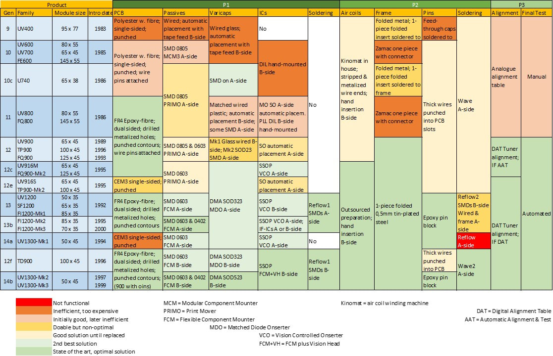
Overview of the production processes for Philips tuners and derived products (mostly front ends) from 1983 till the mixed technology introduction in 1997. Horizontally the last six tuner generations, vertically the technical evolution of the technologies used. The colour coding is an indication of the success and desirability of the different approaches.
|
Tuner assembly started with the component placement on the Printed Circuit Board (PCB). For many years these had contacts and tracks on a single side, limiting the design freedom and being quite bad on RF grounding. The introduction of double-sided FR4 PCB with through-metallized holes in the UV800 was a major improvement, and would - with two exceptions - remain the desired solution from then on. The UV916S and derived TP900-Mk2 returned, purely for cost reasons, to CEM3 single-sided PCB, but in the 900 process flow with wave soldering and therefore posing no problems. The re-introduction of single-sided PCB in the UV1300-Mk1 in combination with single step reflow turned out to be a major disaster, both electrically and production-wise. This solution was therefore replaced by the mixed process as soon as possible.
The UV400 was the last generation to have all components wired. They were placed automatically by a numerically controlled component placement machine, which required a separate preparation step putting all components in the proper placement order in a single feed strip. The UV600 introduced SMDs, making the BU Tuners one of the first users within Philips. The required onsertion machines were developed in close co-operation by the Centrum voor Fabricage Technologie (CFT, Centre for Manufacturing Technologies) and resulted in the Modular Component Mounter (MCM3) which was taken into production and experienced a big business success. A dedicated business was therefore created, Philips Electronic Manufacturing Technology (EMT). MCM3's were hard-coded using so-called program plates, which mechanically stopped the component placing arm at the right position. They were therefore not very fast nor flexible. The next major improvement was the Print Mover (PRIMO), a massive but very fast in-line programmable component placement machine with a very high capacity of 4,5Mio tuners per year. The PRIMO had only one drawback: the placement accuracy was sufficient down to 0805 SMD components, and after quite some fine-tuning 0603 was only just possible (but requiring visual inspection and touch-up/repair). A PRIMO line was also quite expensive, 4MioHfl, but EMT fortunately developed a much cheaper and more flexible alternative: the Flexible Component Mounter (FCM), which became the standard machine for at least a decade. It was fully software controlled and could also place more complex components like SO ICs. The FCM also allowed the move to 0402 and later 0201 components. However, in parallel to these developments two component categories required a dedicated solution: DMA varicaps and SSOP ICs. As described in the varicap section DMA varicaps were packaged in groups of tightly matched components, with gaps between groups to separate them. This required a special placement tool with more intelligence, the Matched Diode Onserter (MDO), developed in close co-operation with the CFT. Likewise SSOP ICs with their very small pinning pitch of 0,65mm required a vision-controlled Topaz machine, later an FCM with vision head. |
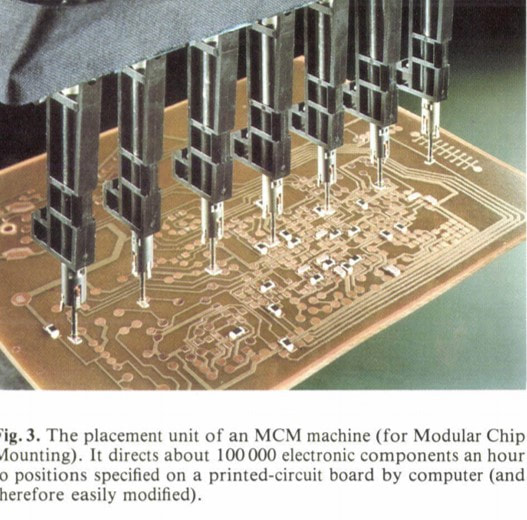
The MCM was a hardware machine, the heads could move in only one lateral direction until stopped by a program plate notch.
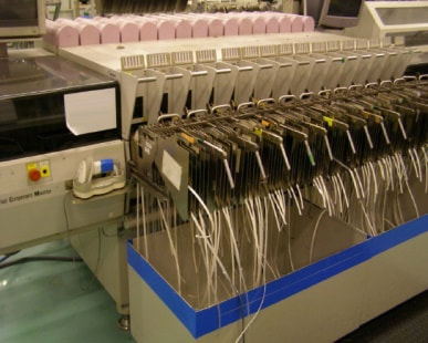
A Philips FCM machine used for SMD component onsertion. Components were fed into the machine with plastic tape on reel.
|
The main struggle throughout these years was to find the optimal component placement and soldering strategy that would support the ever decreasing module size, guarantee good quality and supported cost reduction. One thing was clear: the up to then used single step wave soldering did not support components smaller than 0603 SMDs and SO ICs. However, wave soldering had (so far) one major advantage: it was able to solder in one run through the solder bath the SMDs, wired components like the air coils and the frame, pins and connector. In other words solder joints that required minimal amounts of solder as well as joints that required much more solder and substantial heating due to size of the metal. Reflow, the alternative soldering technology, had the advantage of allowing very small SMD soldering, by reducing the amount of dispensed solder paste, but reflow soldering the frame and ground contacts required much more paste and longer heating time in the reflow oven. It was introduced with the UV1200 and FI1200, where the small form factor necessitated SMD components on both sides of the PCB: the SMDs were mounted in a first reflow step on the A-side, and all other connections including the B-side ICs and frame contacts in a second reflow step. As expected it was very difficult to optimize the reflow settings for all three type of joints, and in practice especially the frame-to-PCB connections required a lot of manual touch-up.
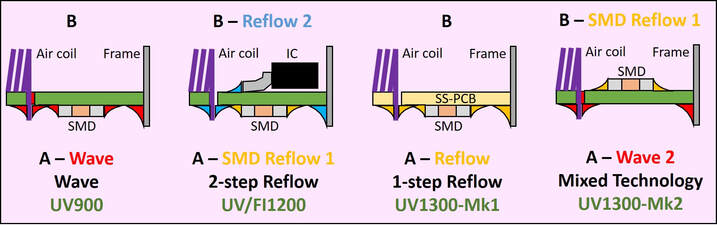
The different component mounting and soldering solutions during the 1990s that ultimately led to the optimal mixed technology.
The most urgent question as to the technology choice was the new WSP tuner, which, as quickly became clear, was under heavy price pressure. Under the argument of lowest cost it was therefore decided for the new UV1300 (only the PLL versions, the VST versions used classical wave soldering) to use single-step reflow in combination with a single-sided PCB, which turned out to be a disastrous decision. So where the FI1200 still had a dedicated reflow step for all A-side components, now these were soldered in the same run as the frame. Where special care had to be taken that the first reflow joints didn't de-solder. The amount of touch-up therefore substantially increased, but now at volumes of a few million pieces. As a result the UV1300 real production cost was much higher, while the BU experienced serious quality problems.
A wave soldering machine in the Singapore Tuner fab.
Another soldering line in the Tuner fab.
|
The solution to this was beautiful in its simplicity: use reflow indeed for small SMDs and fine pitch SSOP, but use proven wave soldering for all wired components and the frame. It was developed in the Krefeld process engineering group of Günther Spee, and first applied in 1996 in the TD900. It proved highly efficient, cheap, eliminating almost all touch-up and providing solid quality. Günther himself came over to Singapore to support the implementation in the UV1300-Mk2. From that moment onwards the mixed process would be the default solution for all products, with the exception of the FI1200 families. (The FI1200 stayed with the two-step reflow for two main reasons: because it was the undisputed market leader in multi media frontends the Philips pinning was the reference, and the application never moved to WSP. But given that, the size of the module was too small to allow all SMDs on one side, requiring the two-step double sided reflow).
Once the mixed process had been standardized process evolution became less dramatic and more in small efficiency details: the absence of components on the A-side created space for an increased number of printed coils, reducing the cost of hand placement of these components; the pin block moved to the outside of the frame to create room for active circuitry; SMDs gradually reduced in size from 0805 to 0603, 0402 and ultimately 0201; for optimal soldering the MOPLL was placed under 45 degrees. |
One of the most characteristic element of tuner manufacturing was the high amount of manual labour. The first element was the hand mounting of all wired components, especially the many air coils. There had been multiple efforts to replace this manual operation by some automated process, but it failed twice. The first time was around 1980, driven by the San Angelo fab together with Kinomat, the supplier of the standard coil winding machine, but this was discontinued when San Angelo was closed in 1982. A second time was around 1990 in Krefeld. They actually developed a prototype machine, which had the coils pre-aligned on long metal rods ("knitting needles"). It never became operational. In the end these efforts to find cheaper automated solutions to compensate European labour cost were defeated by the lower labour cost in Asia; first Singapore, then Batam and finally China. Hand mounting of all wired components thus remained the standard process for tuners. For the 900 and the first generations 1200 and 1300 a manual mounting P2 line typically contained twelve seats, with each operator (there were only young women doing this work, since especially the UHF coils were very small) had to mount 2 components per board with two PCB boards per carrier. At the last station the pre-assembled frame plus RF connectors plus pin block were attached to the PCB. Up to eight tuners were then put into a box that would carry them through the soldering line, either the wave solder bath or the reflow oven.

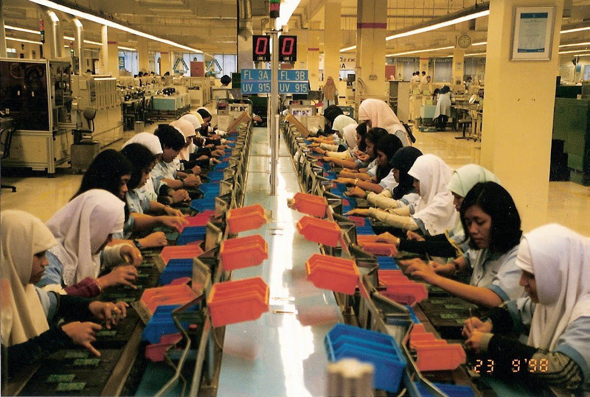
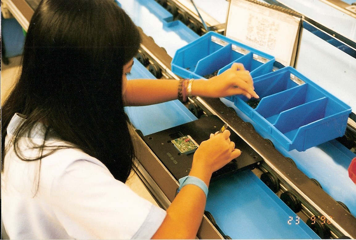


Pictures from the Philips Singapore and Batam tuner factories, mostly from 1998. From the top row by row:
1. A UV900 P2 hand mounting line in Singapore, early 1990s.
2. Two parallel UV915 P2 hand mounting lines in Batam, two times twelve operator seats long.
3. Close up of a UV1336-Mk2 P2 station. Two tuners per carrier and per tuner four coils to be inserted.
4. Eight UV1336-Mk2 tuners ready for the wave solder bath. Note that the tuners will go through the wave with a roughly45 degrees incidence angle.
5. The UV1336 carrier approaching the solder wave. The 200degr Celsius fluid tin bath wave is clearly visible in front.
6. The touch up station after the soldering line. In the back a UV1300-Mk1 line with 4 operators, in front a UV1300-Mk2 line with just one station due to the much more reliable mixed process. [Pictures 2-6 by Pieter Hooijmans, September 1998]
The last manufacturing step P3 was also labour intensive. The tuners, now fully assembled and soldered, should be functional but required proper alignment to guarantee optimal VSWR (by tuning the input circuit), bandpass characteristic (by tuning the BPF primary and secondary tuned circuits), sufficient image rejection (by tuning the image traps) and tracking (by tuning the LO tanks). All this for each band, usually done once at the lower band edge and once at the upper edge. Finally the IF output filter, when present, required alignment to the centre IF. Most of these alignment adjustments were done by splitting or bending an air coil, using plastic wedge tapered rods. Since the mid 1990s P3 operators used the Digital Alignment Table (DAT), obtaining visual feedback from a colour monitor attached to a 486-core PC. It displayed the tuning or VSWR curve with markers and coloured bars for image. The DAT used a standard PC running a C-program in combination with an RF signal handling box, containing a synthesized RF generator, 75 Ohm VSWR bridge and IF Digital to Analogue Converter (DAC), designed by the Elektrisch BetriebsMittel (EBM, Electric Production Equipment) department in Krefeld. A trained DAT operator could align 35 tuners per hour. In total 160 DATs were used in Singapore/Batam and another 40-50 in Krefeld/Kwidzyn. Other products like front ends (FQ900 and FI1200, SF1200) and the TP900 mostly required simpler alignment operations: setting of sound traps by turning the core of transformer modules, or potentiometers for e.g. AFC, AGC, modulator setting etcetera. These could be done manually but increasingly - especially in Krefeld - were done using automated machines. A last step was the final test, which was automated, and only performed a set of critical measurements using the commercial spec limits. The finished products were then packed in cardboard boxes.
The P3 area in the Philips Batam factory.
|
Close up of a P3 alignment station. The passband curve and image bars are clearly visible on the PC screen.
|
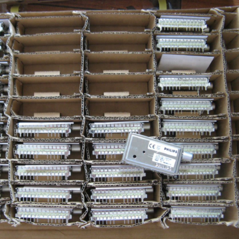
A typical box for shipping products to customers, made from currogated cart board. Note the stand-off piece under the tuner to avoid bending of the horizontal mounting pins.
|
As explained earlier, the BU Tuners went through an extensive program of reducing production sites, in combination with a steady move to Asia. However, throughout all these moves it succeeded to a very high extent to keep its manufacturing processes standardized across the fabs, allowing the flexibility to move products between sites.
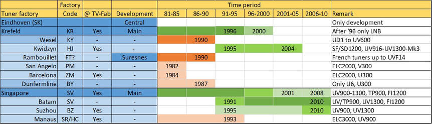
Overview of the Philips BU Tuners production facilities from 1980.
Towards the end of the decade, in 1998, the 26Mio units production capacity of the BU was divided across the fabs as follows:
- Batam: 9 lines P2+P3 (14Mio units)
2x UV900, 1x TP900-Mk2, 2x UV1300-VST wave, 2x UV1300-PLL mixed technology, 2x FI1200-Mk2 - Singapore: all Asia P1 plus 3 lines P2+P3 (4,5Mio units)
1x UV1300 mixed, 1x TP900-Mk2, 1x FI1200-Mk2/UV1200 - Suzhou: 2 lines P2+P3 (1,5Mio units)
1x UV900, 1x UV1300 - Kwidzyn: all Europe P1 plus 4 lines P2+P3 (5Mio units)
1x UV900, 1x UV1300 mixed, 1x TP900-Mk2, 1x SF/SD1200 - Krefeld: 1 line P1+ and P3 LNB (1Mio units)
World Standard Pinning (WSP), 1992
|
One of the most remarkable developments in the world of tuners was the definition of the World Standard Pinning (WSP). One thing is clear: the initiative that ultimately led to the WSP was taken by Philips. Some time towards the end of the 1980s it took the initiative to start discussions with its two main competitors Alps and Matsushita Corporation (Maco). Talking amongst competitors is always a dangerous thing, but the discussions were restricted to the market size, shares and developments. Each of the companies took turns to host the discussion, on average 2-3 times per year. During the discussions the companies agreed that there was a de facto split of the world between the Europe-centric Philips pinning and interfacing (roughly 25Mio tuners/year), and the Asia-centric Japanese dominated pinning (roughly 75Mio/year) plus some 13Mio/year of other pinnings. Size was roughly the same on both sides, although Japanese tuners tended to be a little smaller. Another major difference was the 2-wire I2C-based interface invented and driven by Philips versus the Japanese so-called 3-wire (3W) bus. Somehow the common view emerged, undoubtedly based on suggestions by Philips, that a joint standard would open markets then not addressable, with potential benefit for all. Because all parties were extremely careful, the first step of WSP was restricted to standard terrestrial tuners, excluding tuner-modulators, front ends of 3-in-1s for VCR.
|
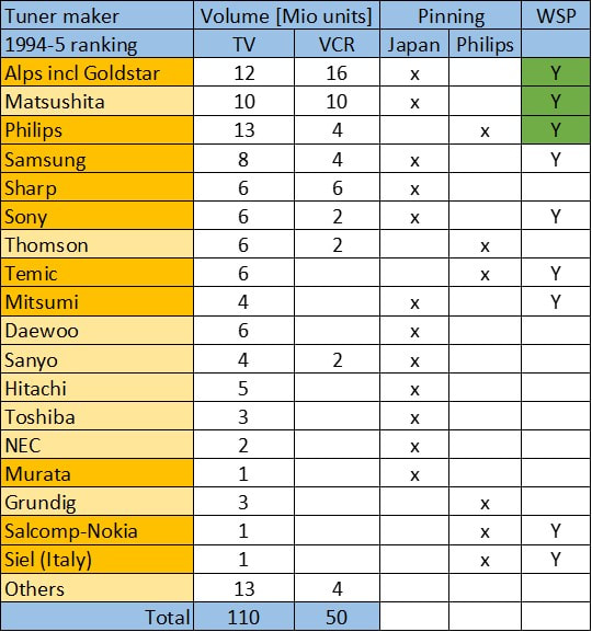
Estimated tuner maker volumes in 1994-95, volumes rounded in Mio units for TV and VCR applications only. The first 18 tuner makers are listed, but in total there were some 35 different companies!
|
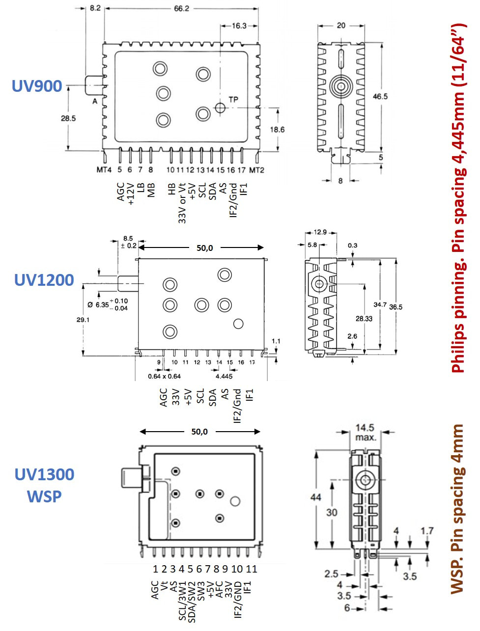
Comparison of the mechanical standards for the UV900, UV1200 and the new WSP UV1300 families.
|
Why did Philips, or more specifically Johan Visscher as the head of the BU Tuners, support the WSP proposal? At this time it sold some 12Mio tuners per year, 95% of which internally in its still captive internal market plus a few 100.000 tuners to external customers, almost all to the few remaining smaller European TV set makers (Bang&Olufsen, OTF, Vestel) but increasingly also to Japanese set makers (Sony, Panasonic, Sharp) that used Philips tuners for their European-produced chassis (and thus avoiding having to develop the exotic Amtsblatt, French or UK tuners). The big frustration of Philips, at least, was that they sold almost nothing in the faster growing Asian market, mainly due to the unwillingness of customers to use Philips pinning based tuners instead of or next to the Japanese pinning. Undoubtedly the Japanese tuner makers had similar thoughts about capturing share in the European market. The WSP tuner should take away these boundaries!
What surprises me most is that there was a genuine belief that WSP would only give additional sales. The internal strategy of the BU Tuners was very clearly to keep Philips internally 100% on the Philips pinning and use WSP only on the external Asian market. Assuming that the Japanese would reason similarly, this effectively meant WSP would in such a scenario become a third pinning standard not a replacement of the current ones. A totally naive assumption, as we'll see next. |
|
In the meantime discussions between the three companies progressed well, and the WSP emerged as nice compromise between the then standard Philips UV900 and Japanese tuners: smaller than the UV900 but bigger than the UV1200 (and roughly the same size as the latest Alps tuner), pinning resembling the Philips one, but with different pitch. Furthermore the WSP was only a mechanical standard, it said nothing about the internal tuner concept (e.g. switched-2B vs. 3B, band edges, 3W vs. I2C et cetera). For band switching and control three pins were reserved, which could be either I2C or 3W-bus for PLL tuners . For VST tuners there was one pin for each band, although the switching mechanism was not yet prescribed. Early 1992 all three companies had made prototypes of a WSP tuner to verify they were able to make such a product, and the question came up how to announce it to the world. October 1992 a conference was therefore organised in Tokyo, with invitations sent to all known tuner makers, where Johan Bos, the then Eindhoven Tuner Development Manager of Philips, had the honour of presenting the proposal on behalf of the Consortium. It was received with a standing ovation and from that moment on the WSP was a new tuner standard.
|
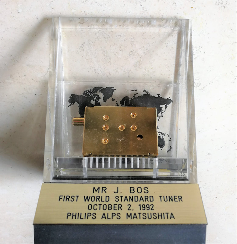
A commemorative standard that was given to the participants when the WSP was announced in 1992. [Johan Bos collection]
|
Very quickly some ten companies announced they would introduce WSP tuners. What is interesting, compared to other more formal standards and protocols, is that no standardization body was established to supervise and possibly extend the standard. The (tuner-only!) WSP proposal was communicated once, and then all players stuck to that guideline. As such it was more a recommendation then a standard. On the other hand, this lack of formal standardization also reflects the hesitance by all (three) major players to really go for a common standard. Interestingly, after this WSP announcement the informal discussions betwee the Philips, Maco and Alps almost immediately ended.
TDA6402, the first MOPLL IC, 1995
After the successful introduction of the mixer-oscillator (MO) IC in the UV600 in 1985 and the phase locked loop (PLL) IC in the UV800 in 1990, the next integration step had always been defined as the MOPLL, i.e. the integration of MO and PLL into a single IC. This was an agreed target of Semiconductors and the Tuner group, and work had started around 1990. However, this was a far from obvious step, especially given the technology used: still SUBILO, a technology dating back to 1978. Good 5V 3-band MO ICs (the TDA5730 family) and 5V PLL ICs (the TSA5520 family) were possible, but combining them on a single die with proper isolation between the different sensitive blocks was much more difficult. The development therefore went slowly with ICs initially baptized TDA6400 and later TDA6401. It quickly turned out that 3-band European Cenelec performance was out of reach, so the new IC target became NTSC for the US and Latam markets. To avoid a switched concept it was explored whether the IC could be used in a real 2-band configuration (with bands 55-270 and 270-801MHz) but also this was to ambitious, and the IC finally settled on a switched 2-band architecture, and became the TDA6402, with its mirrored version the TDA6403.
|
Because the main challenge was the single die integration, the TDA6402/3 was first order a straightforward combination of a switched 2B-MO and a TSA5522 PLL. Some specific features were:
|
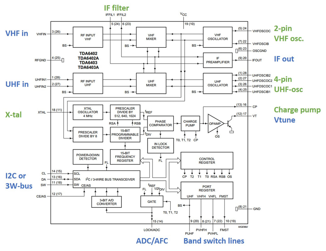
Block diagram of the Philips TDA6402 and TDA6403 switched 2-band MOPLL IC. [Philips Semiconductors Data Sheet 1996]
|
The TDA6402 family was about the very last IC to use the old Caen SUBILO technology, and performance on critical parameters was often marginal. The IC also showed increased breakthroughs of the 62,5kHz divider frequency and its multiples, due to insufficient substrate isolation. But it was an integration milestone!
UV1300 WSP tuner, 1994
|
The initial Philips strategy with WSP was to use it exclusively for obtaining higher market share on the external (Asian) market. The initial types developed were thus typical Asian models: VST off-air (UV1313 for PAL-B/G and UV1353 for PAL-D/K), VST S-channels (UV1317 for PAL-B/G and UV1357 for PAL-D/K) and VST hyper-band for cable (UV1315 and UV1355), which were developed as one PCB with different components and alignment for both versions (38,9 and 38,0MHz IF). The UV1313 was the first Philips WSP tuner, with development started end of 1993 and released in 1994, followed by the UV1357. All these VST tuners used the WSP wave technology:
|
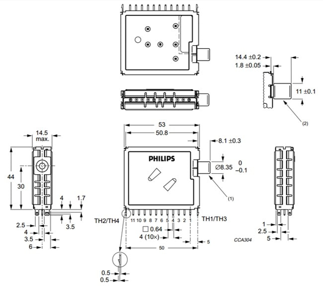
Mechanical dimensions of the Philips UV1300 WSP tuner family. [Philips Components UV1316 Data Sheet]
|
Design-in of the WSP tuner was slow, the entire TV world was looking at each other to see who would introduce it and with which speed. The customer discussions also showed the first down-side of having only a mechanical standard: most Asian customers still used 9V tuners, and the Philips 5V UV1300 was simply too advanced. Also,the UV1357 S-channel tuner was not needed because everybody now wanted full hyper-band coverage. But the big shock that hit the tuner organization was the announcement of the Philips BGTV that they intended to switch to the WSP, away from the good old Philips pinning. This had clearly not been the intention of the BU Tuners! The immediate impact was dramatic. Not only was the full range of global tuners requested , but TV Purchasing made clear they would use the WSP to target aggressive cost reduction by benchmarking the internal offers against those of other suppliers. De Ridder, the BU manager, was in no position nor willing to refuse, and so development started of a much wider range of 1300 tuners under a heavy cost pressure.
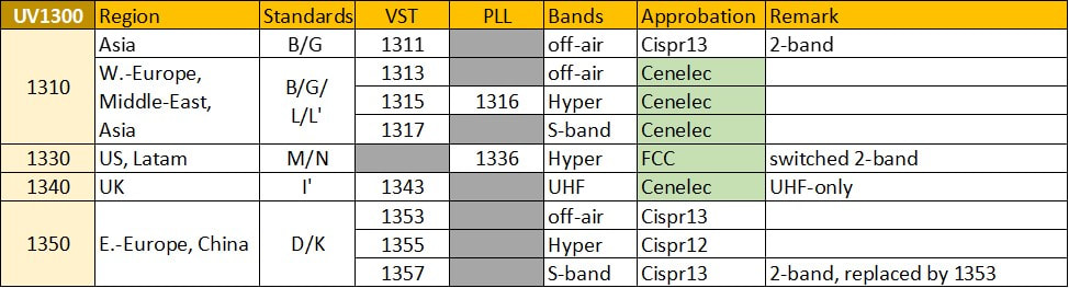
The tuner types that would form the first generation Philips UV1300 WSP tuners.
|
In an effort to limit the amount of design work and number of different PCBs, types were as much as possible combined in one design: UV13115/1317/1355. In a certain way the BU was lucky that PLL tuners were not yet requested in Asia. In contrast the U1343 UHF-only UK tuner was very expensive since based on the depopulated UV1315 3-band MO-IC design. The main burden of the UV1300, however, were the first two PLL versions: the UV1316 PAL and UV1336 NTSC tuner.
|
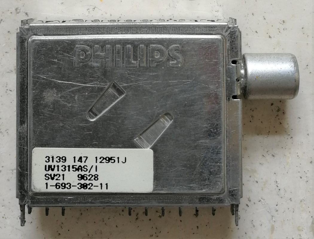
The Philips UV1315AS/I, one of the first WSP models really produced in volume. The UV1300 introduced the Philips name embossed in the top cover. [Oswald Moonen collection]
|
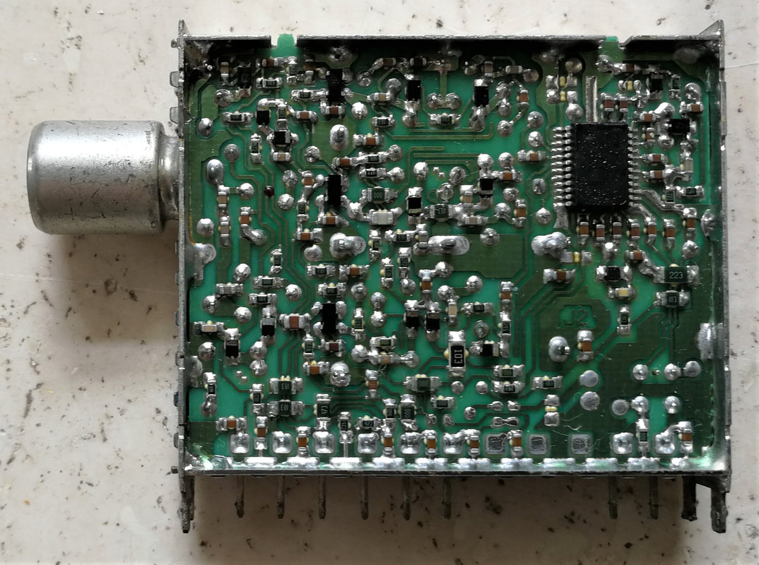
Soldered A-side of the UV1315AS/I. Despite the SSOP MO-IC the tuner is wave soldered. The three input MOSFET are neatly aligned above each other on the left side of the tuner.
|
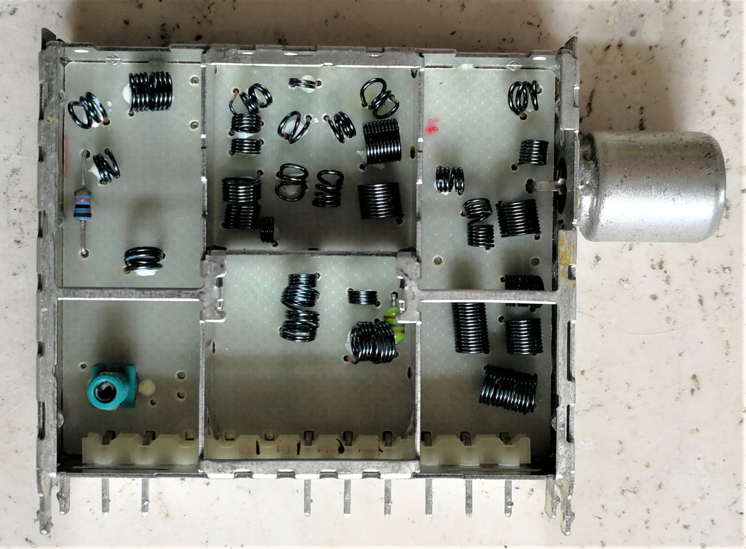
The B-side of the UV1315 with the hand-mounted components. Lower left the Sagami transformer for the symmetrical to asymmetrical IF out conversion.
|
The first PLL type, the UV1316, was fairly straightforward in its design: the UV1315/55 3B MO-IC Cenelec tuner (based on the TDA5736) with a PLL IC added (the same 5V TSA5518 as used in the FI1200-Mk1). Or in other words a re-layout of the double-sided UV1216 (and thus the tuner section of the FI1216) into a single-sided UV1316. Because wave soldering of two SSOP ICs would give too many fall-off, touch-up and repair problems, it was decided to use the 1-step reflow solder process instead. This clearly improved the soldering reliability of the SMD and SSOP components, but shifted the problem to reliably soldering of the frame contacts. It still required a lot of touch-up! The tuner therefore never really moved into production, and it took almost 2 years before the project obtained Industrial Release status end of 1997. By then the UV1336-Mk2 was already released, and volumes of the Mk1 were minimal.
|
The second PLL type that was developed was the UV1336, based on the very first MOPLL IC, the TDA6402. BU management was very eager to use the MOPLL since this was seen as an important driver for cost reduction: the price of an MOPLL should by definition be lower than the combined prices of the MO and PLL. At the time of introduction this was just below 1USD. (Semiconductors was always very reluctant to go along with this reasoning, arguing that integration increased the value of the IC. But these were mainly delay tactics, and in the end they were forced to offer the reduced prices after again having troubled the relation). As we've seen in the previous section the TDA6402 had to be a switched 2-band IC due to a lack of available pins, but this had a major impact on the tuner design. It had been a long time since the BU Tuners had made switched-band tuners fulfilling either Cenelec or FCC requirements; in contrast to its main Japanese competitors it used 3-band tuners for high performance. The problem with using a different core concept is in principle not the wanted-signal performance, which can be designed and measured rather easily, but much more the subtle tuner behaviour related to breakthroughs, out-of-band characteristics, non-linearities, radiation and other Cenelec/FCC requirements. It is therefore no big surprise that development was struggling to meet the original performance targets, and with the message to BGTV "you want a cheap tuner, then you get lower performance" a number of parameters like NF and cross-modulation were reduced in specification. On top of that the TDA6402 MOPLL showed the mentioned 62,5kHz (the phase comparator frequency) spiky noise, requiring design changes.
|
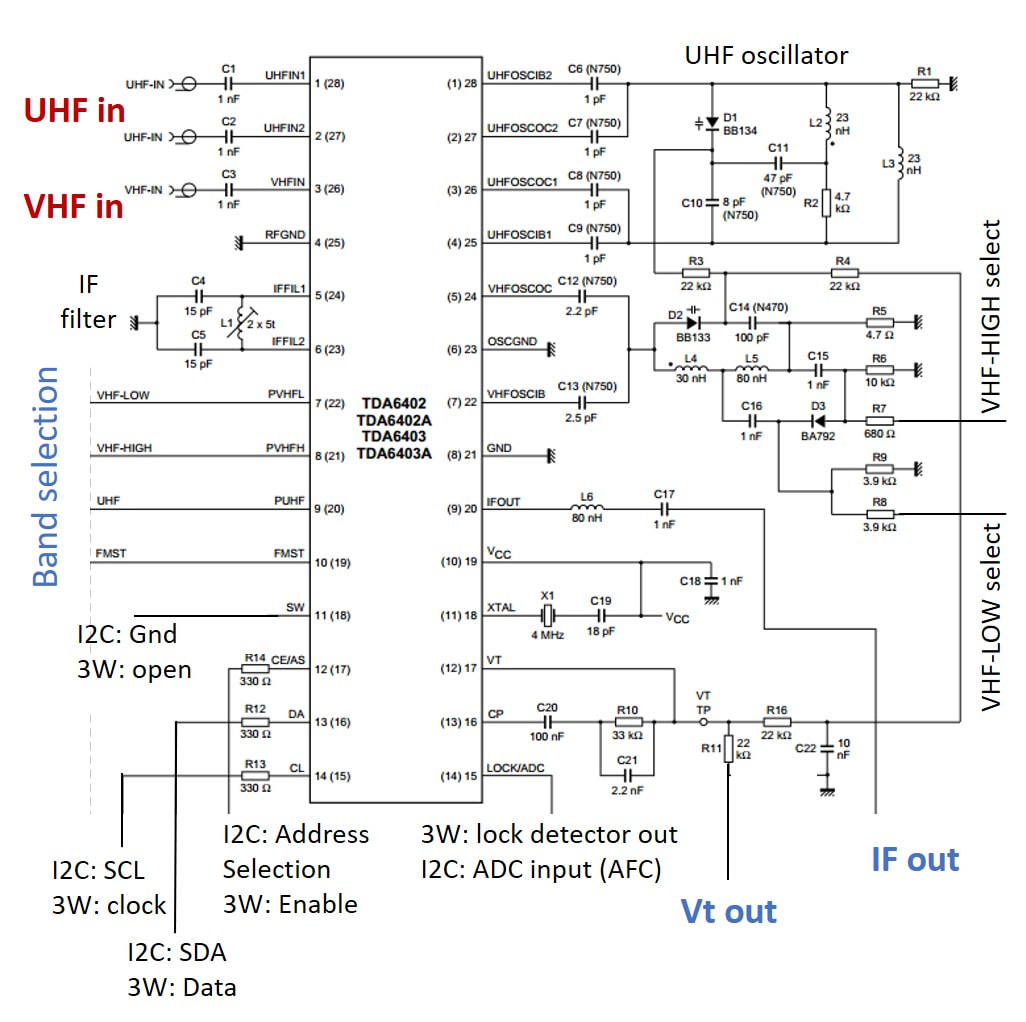
The reference design of the TDA6402 as also used in the UV1336. For selecting VHF-low the diode D3 is put in reverse bias such that L4 and L5 form the oscillator tank inductor. For VHF-high D3 is put in forward mode, by-passing inductor L5. [Philips Semiconductors TDA6402/6403 Data Sheet, 1997]
|
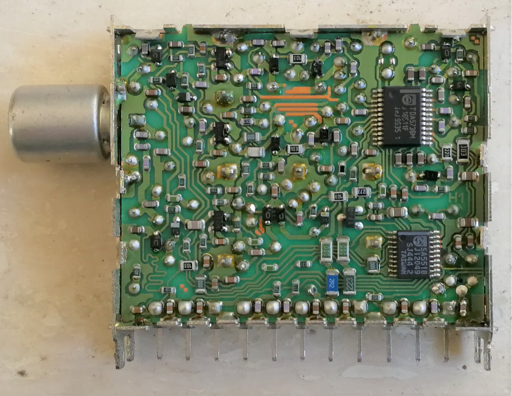
The Philips UV1316, a classical 3-band design with left the three MOSFETs and on the right the TDA5736 MO-IC on top and below the TSA5518 PLL. [Johan Bos collection]
|
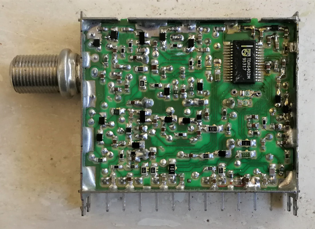
The Philips UV1336 2-band NTSC tuner, the worlds first tuner with an MOPLL! Wave soldering solved the fine-pitch SSOP soldering, but all frame contacts are touched-up by hand. [Johan Bos collection]
|
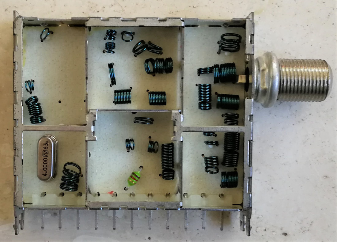
The B-side of the Philips UV1316 and UV1336 looked very much identical, this is the 1336.
|
Although there were strong statements of BGTV Purchasing that they would use the UV1300 as soon as possible, discussions with the responsible TV design centres on the actual implementation were much more difficult. The original target was to use the VST models UV1313 (off-air), UV1317 (S-channels), UV1315 (hyper-band) and U1343 (UHF-only) in the Dreux L6 platform, targeted for 1996. But Dreux development was not inclined to switch to WSP, staying with the UV900 VST tuners for the L6 chassis and introducing the UV916S as cost reduction for the Mid1 and Mid2. The next chassis became the Low7 or L7, targeted for 1997 launch. In the meantime some substantial re-organizations were taking place within the BGTV, and in 1996 Dreux and Monza development were closed, with the responsibility for global low end design now in the Singapore TV Lab. The L7 was therefore a prestige chassis for the Singapore TV organization, which was strengthened by tens of engineers and managers from the reducing Dreux and Eindhoven organizations. The L7 was the first low end chassis to switch completely to I2C-control, and thus also the first using PLL tuners: the UV1316/U1344 and UV1336. (For China, Eastern Europe and Russia it still used the UV1355 VST tuner). The whole chassis was centred around the Philips Semiconductors TDA8374 economy multi-standard 1-chip TV IC, and the single-standard NTSC version TDA8373.
A 14" model of the infamous Philips L7 chassis, the 14PT1405/94, the /94 indicating it was a set for the Indian market, produced in Puna.
|
A larger 21" screen L7 versions, the 21PT1181, 21PT1321 and PT1381, which all looked identical.
|
|
Disaster struck during the last field trial run of the L7 in April 1997, with production ramp planned for June. Field trials were always done at locations with notoriously bad reception conditions, in this case Rio de Janeiro in Brazil. Rio, being one of the largest cities in the world, used a TV tower in the centre of the city, transmitting many closely-spaced channels at fairly high powers. Especially in VHF-I channels 2, 4 and 6 were all used, potentially giving N-2 interference. Which is exactly what happened. Although the TV organization had already done multiple field trials and never reported any problems, now severe N-2 interference was detected, to an extent that made the set unusable under the (extreme) Rio broadcast conditions. BGTV being much bigger as well as the customer put the blame entirely on the smaller supplier BU Tuners. Which had a serious problem now! In fact all not-so-good decisions from the previous years worked together to make this a difficult to solve problem:
On the short term not much could be done. The N-2 problem mostly manifests itself in VHF-I because the tuner BPF characteristic is widest there; typically 8-10MHz with a modest roll-off. As a consequence N+/-2 interferers are insufficiently attenuated and the combined signal of wanted channel plus adjacent channels on the mixer is much higher than permitted to avoid mixer overloading and non-linear distortion. So the first measure was to set the AGC TOP lower, while reducing the tuner gain slightly. This of course slightly reduced but didn't solve the problem. That had to wait for the next generation. This first interim version was produced as UV1336-Mk1b. All in all the UV1300 started off on the wrong footing, especially with the internal customer BGTV. Fortunately, other areas targeted by the L7 NTSC version, mainly the PCEC US version, accepted the UV1336 performance, and in 1997 still 4,5Mio of these tuners were produced. At the same time BGTV had decided to give all Western European tuners in the L7 to Alps, which meant that the UV1316 was not required nor produced. And also the Latin America quantities, in view of the field trial performance, went to Alps. As an extra punishment the entire A8 volume with the exception of the PCEC share, so in total 1,1Mio tuners, went to Alps, which by the end of 1998 had taken over 20% of the BGTV tuner share. This in combination with the severe price erosion triggered by the WSP meant a serious blow for the BU Tuners, unfortunately mainly due to its own management failures around WSP introduction tactics and the first generation product definition.
In contrast the VST tuners for Asia and Eastern Europe were not doing that badly, seeing increasing design-ins of the UV1311, 13, 15, 55 and 57, mostly, and, that was promising, with new external customers like Peacock and Great Wall in China, Hartono in Indonesia and Vestel in Turkey. But whatever the situation, the BU was now into the WSP and had to make the best of it. |
Tuner Theory 12, N-2 interference
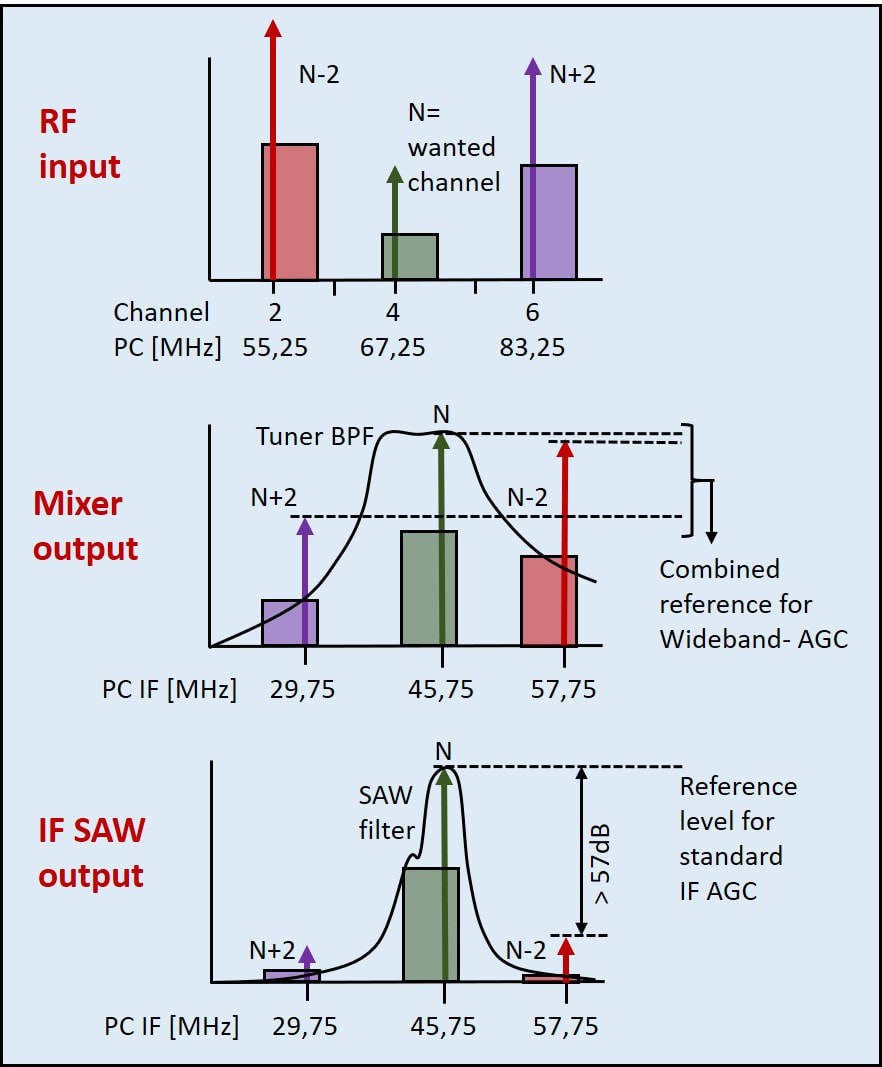
N-2 (or more in general N+/-1 and N+/-2) problems appear when very strong adjacent channels are insufficiently filtered by the tuner band pass filter (BPF). Normally the Automatic Gain Control (AGC) Take-Over Point (TOP) is set such that the wanted signal has a certain maximum level. Providing more gain would rapidly increase non-linear distortion in the mixer. Standard AGC uses the output of the IF SAW filter for AGC. However, strong N+/-1 and +/-2 signals (say 30dB stronger than the wanted signal, top diagram) can be of the same amplitude at the mixer as the wanted signal, especially when (as at VHF-I) the BPF is typically much broader than one channel (centre diagram). The combined signal strength at the mixer is then (much) higher than for a single wanted channel, resulting in overloading of the mixer and picture distortion. A wideband AGC (W-AGC) that uses the combined signals at the mixer output as reference can avoid this problem (as can steeper filtering). See Tuner Theory 13 for W-AGC.
Top view of the Philips L7.1 low end chassis, with upper left the UV1355. This is the 14PT138A/58 for Russia. [Espec.ws]
|
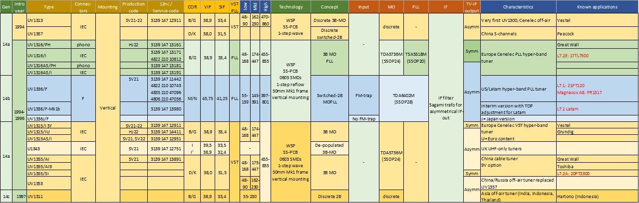
Overview of the Philips UV1300-Mk1 WSP tuner family. It was only used internally in the L7 low end and the US A8 mid end chassis, otherwise mostly by (new) external customers.
Tuner Theory 13, Wideband AGC
|
Wideband AGC is probably the biggest tuner innovation since the introduction of varicaps. It solves a major signal handling problem in case of very strong adjacent (N+/-1, N+/-2) channels. The main reason for these problems is the fact that, in order to provide proper tracking of BPF and LO while tuning, the tuner BPF can not be too narrow. In UHF, where the Q of the filter is much higher (Q=BW/fc) this is less of a problem, but especially in VHF-I it is a major issue. BPF width is then in the order of 10-12MHz worst case, which means that the strong adjacent channels are barely attenuated compared to the wanted channel. At the output of the mixer and the IF filter the interferer can still be many dBs higher; in the example below we'll use 25dB, so almost 20x in terms of voltage.
|
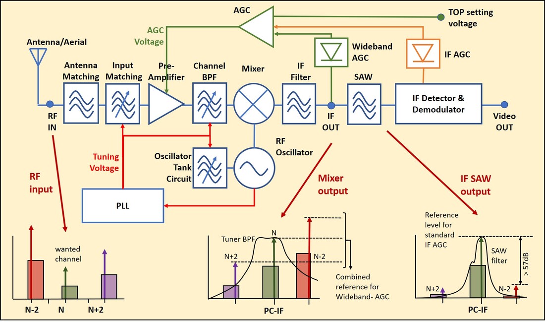
Tuner block diagram including the AGC control loops: orange for standard IF-AGC, green for Wideband AGC. At the bottom typical signals for worst-case N-2 conditions, with N-2 much stronger than the wanted channel N.
|
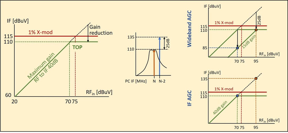
Principles of AGC Take-Over Point setting, and the effects of normal IF-AGC and Wideband AGC on signal handling.
|
Under normal condition (let's assume single channel reception) the Automatic Gain Control (AGC) sets the output signal of the tuner to the maximum permissible level. This will guarantee maximum SNR and minimal distortion. To achieve the latter the tuner output is usually set a few dB below the level where 1% cross-modulation occurs. The few dB is for system margin, typically 5dB. This output level is called the Take-Over Point (TOP), which was usually 110dBuV at the IF for Philips tuners. With a typical gain of 40dB this is equivalent to an RF input signal strength of 70dBuV. For all input signals weaker than this 70dBuV the tuner provides maximum gain (here 40dB). For all signals stronger than 70dBuV the AGC takes over (therefore Take-Over Point) and reduces the gain to keep the IF output level at 110dBuV, preventing it becomes higher than the 115dBuV 1% X-mod limit.
|
The two diagrams above now illustrate the major difference between a classical narrow band IF-AGC and Wideband AGC. In case of IF-AGC the detector, which is at the output of the very steep SAW filter, only sees the wanted channel, and the AGC will thus still provide maximum gain to make the wanted signal output 110dBuV. The IF-AGC essentially doesn't see the N-2 interferer, which will also be amplified with 40dB and provide a (theoretical) IF output level of 135dBuV, far above the 1% X-mod limit. In practice the mixer and amplifiers will show clipping and generate excessive levels of non-linear distortion, which will result in a heavily distorted TV picture (if the set will synchronize at all).
Wideband AGC in contrast detects all signals at the mixer IF output, which makes that the AGC loop adjusts to the highest level, in this case the 25dB stronger N-2 interferer. The interferer level will thus be kept at 110dBuV at the IF output, below the X-mod limit and thus preventing the occurrence of cross-modulation. But the 25dB weaker wanted signal will only have an output level of 85dBuV. Effectively it means that the W-AGC has shifted the TOP-curve of the wanted signal (the solid green line) down by 25dB. This will result in an SNR degradation of the wanted signal, resulting in a more noisy picture, but the channel will be perfectly stable to watch and not show any distortion.
Wideband AGC in contrast detects all signals at the mixer IF output, which makes that the AGC loop adjusts to the highest level, in this case the 25dB stronger N-2 interferer. The interferer level will thus be kept at 110dBuV at the IF output, below the X-mod limit and thus preventing the occurrence of cross-modulation. But the 25dB weaker wanted signal will only have an output level of 85dBuV. Effectively it means that the W-AGC has shifted the TOP-curve of the wanted signal (the solid green line) down by 25dB. This will result in an SNR degradation of the wanted signal, resulting in a more noisy picture, but the channel will be perfectly stable to watch and not show any distortion.
UV1300-Mk2, technology consolidation, 1997
Already before the UV1336-L7 disaster happened it was obvious that the UV1300-MK1 had to be replaced as quickly as possible. First the production of the single step reflow UV1336 was extremely cumbersome, with a lot of visual checks and manual touch-up, making the cost much to high. Where the UV1336 required volume production, the UV1316 was simply not taken into production at all. The VST models, using wave soldering, had less problems but still required quite some touch-up given the SSOP MO IC. Secondly the single-sided PCB made it difficult to achieve performance at the level of the UV900, making it hard to compete on the open market. And thirdly it was quickly becoming obvious that WSP was only a mechanical but definitely not an electrical standard. Customers or applications were increasingly asking for additional features and functions, often related to performance under bad reception conditions (wide-band AGC, FM-trap, Citizen Band (CB) trap, extra Low Noise Amplifier (LNA)) or the application (9V power supply, symmetric or asymmetrical IF output, loop-through splitters for dual tuner PIP). And marketing requested products that were a drop-in replacement of the Japanese competition, which used (due to the switched 2B concepts) different band edges than the BU 3B tuners, or different band switch decoders (inverted 3bit or 2bit). Also the success of the FR1200 and FM1200 with FM-radio reception led to similar requests for the tuner, while finally 2nd sourcing of the main component (the MOPLL) required its dedicated product versions. As a result of all this the UV1300-Mk2 became a much more diversified family.
|
The first and most important decision was to convert the UV1300 to the Krefeld mixed technology: reflow soldering of all SMD and SSOP components on the B-side, followed by wave soldering of all wired hand inserted components as well as frame-connector-pin block assembly on the A-side. To speed up the implementation the group leader of the Krefeld process technology group, Günther Spee, came to Singapore. It immediately solved all manufacturing-related issues, and obviously the mixed technology became the standard for all subsequent generations.
Roll out of the UV1300-MK2 appeared in three waves:
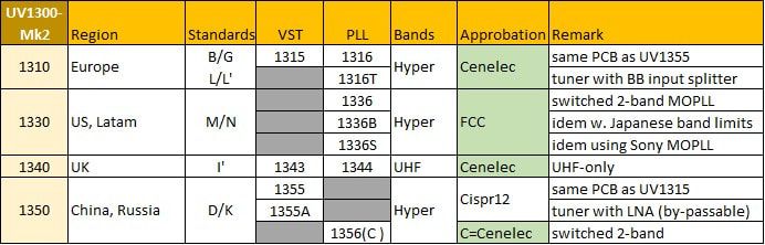
Overview of the UV1300-Mk2 tuner family, including its special types.
Where the UV1316-Mk2 development and application was straightforward, not encountering any issues, the UV1336-Mk2 remained the problem child. Although the double-sided PCB gave some additional margin for reaching the critical performance parameters, it continued to use the TDA6403 switched-2B MOPLL, and its overall performance thus remained lower than the 3B UV1316-Mk2. But worse, while the BU was frantically working on solving the UV1336 problems, BGTV went ahead by using the Alps TELH9 NTSC tuner in Latin America, which used different band edges than the UV1336. So when the BU finally had its UV1336 performance issues solved and tried to get back into the Latam chassis of the L7 successor L9, it was told that the Philips tuner needed to be fully drop-in compatible with the TELH9. This meant a redesign to adjust the band edges, which was the UV1336B. This tuner also introduced the Wideband AGC function, the only practical solution to the Rio de Janeiro field conditions, often in combination with an N-1 trap in the IF. Also, depending upon the region, it had a switchable FM-trap at the input. And finally the UV1336 was used to push second sourcing a step further by introducing the Sony CXA3236 switched-2B MOPLL as an alternative to the TDA6403. However, this IC used an SSOP30 package instead of the SSOP28, requiring yet another lay-out (as well as the Topaz vision-controlled component mounter). The S-version with the Sony IC was used for sales to external customers Sharp, CCE and Mitsubishi.
|
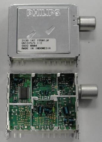
The Philips UV1315-Mk2 full band B/G Cenelec VST tuner. This tuner introduced the 1300-Mk2 frame, with the left inner screen moved to the right, enlarging the LO space. Note the large unused board space, which was reserved for a discrete W-AGC (left) and/or 2-bit decoder (centre).
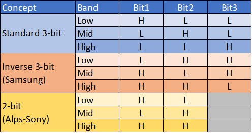
The different VST band switching concepts used in WSP tuners. The UV1315/55-Mk2 supported them all; 2-bit = suffix B, inverse 3-bit suffix O.
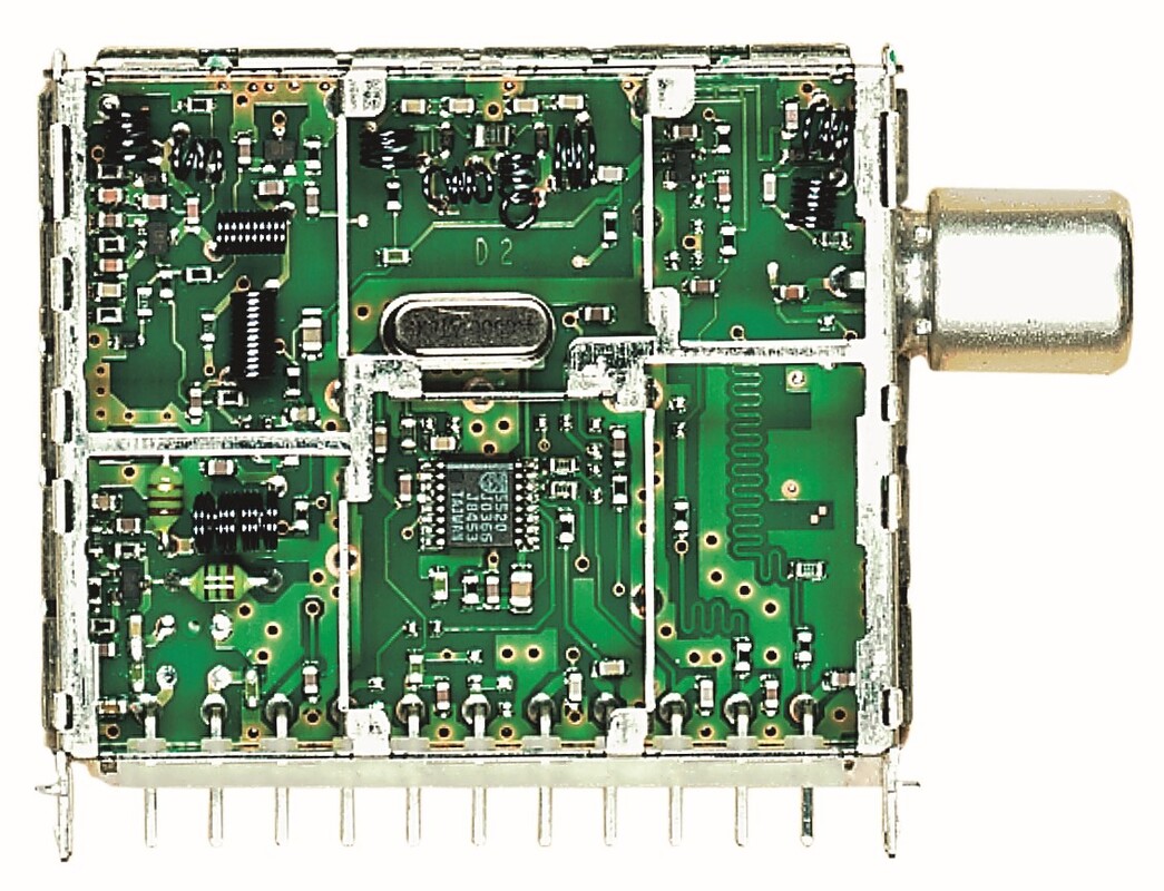
The Philips UV1300-Mk2 family finally saw a dedicated UK tuner, the U1344 with discrete single-band MO and PLL. For the U1343 VST version the PLL was omitted. [Darko Jancin]
|
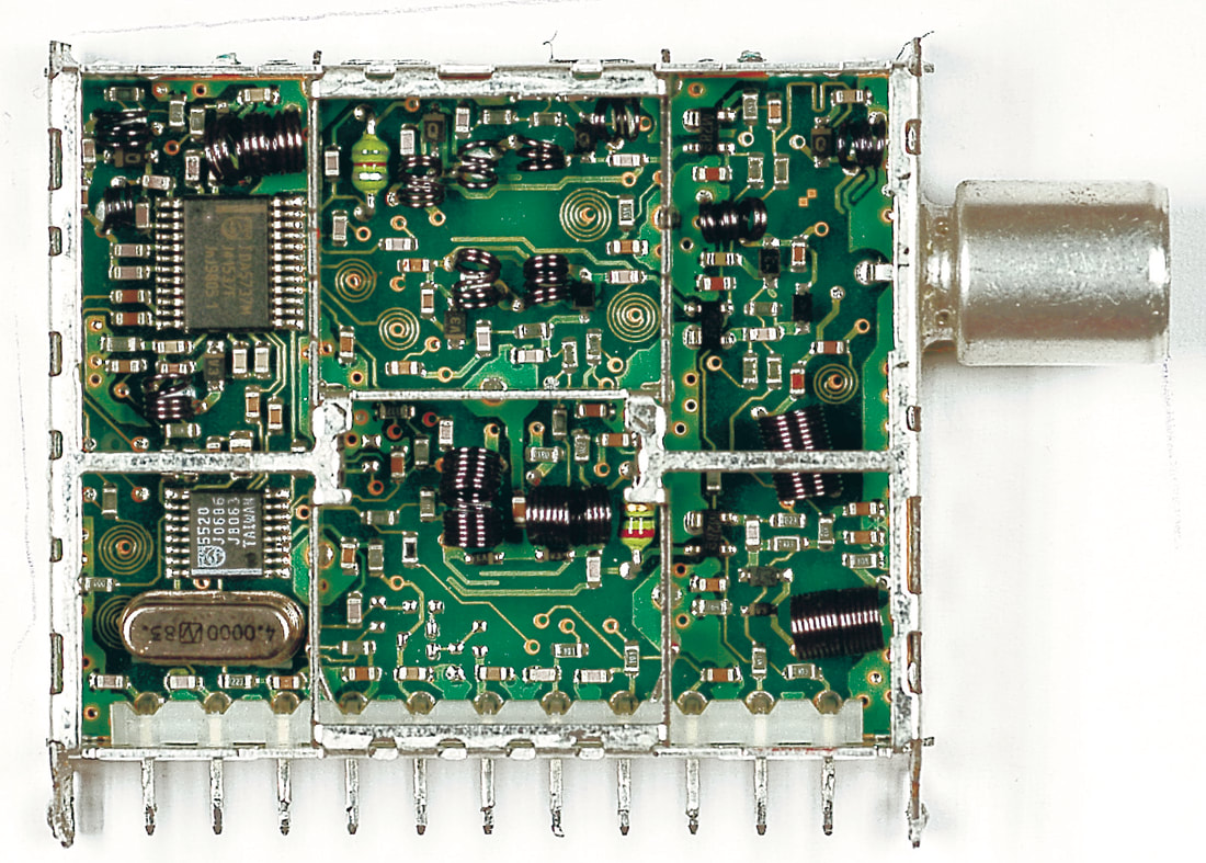
The Philips UV1316/AI-2 tuner, the standard tuner for B/G-PAL and one of the highest volume versions. Note the separate 3B-MO and PLL ICs. [Darko Jancin]
|
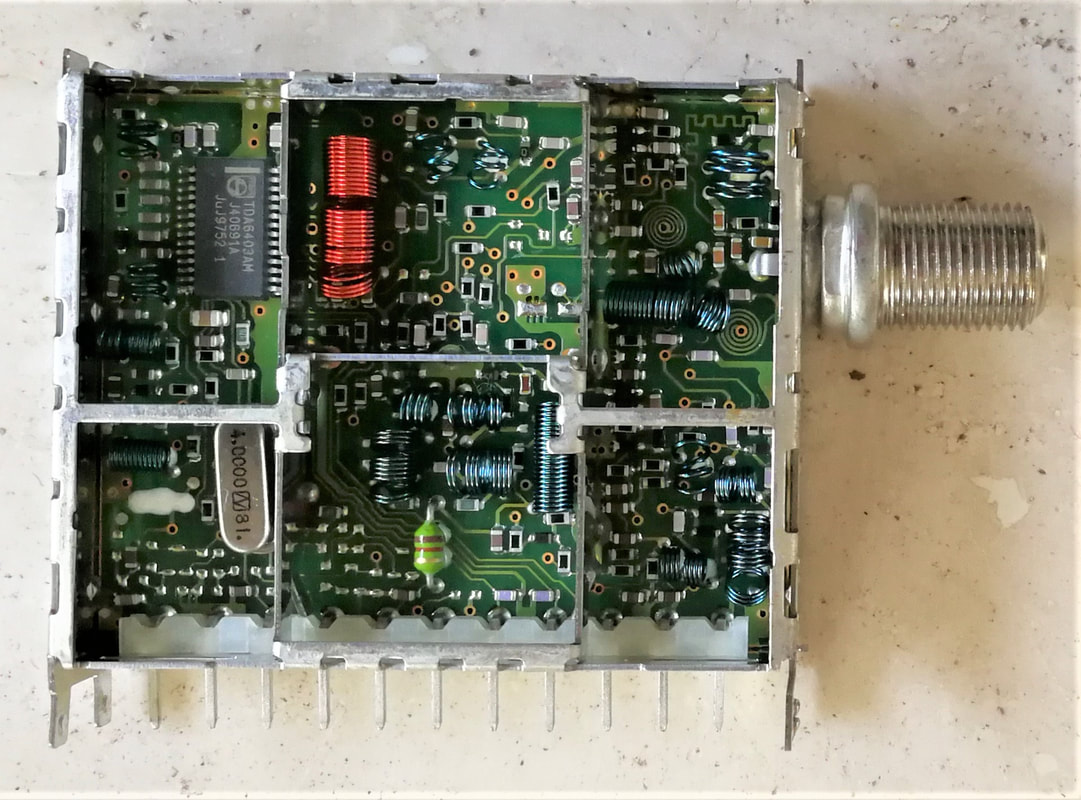
The Philips UV1336/AF-2, still using the switched-2B MOPLL. Note the space lower left for the W-AGC (not mounted here). [Pieter Hooijmans collection]
|
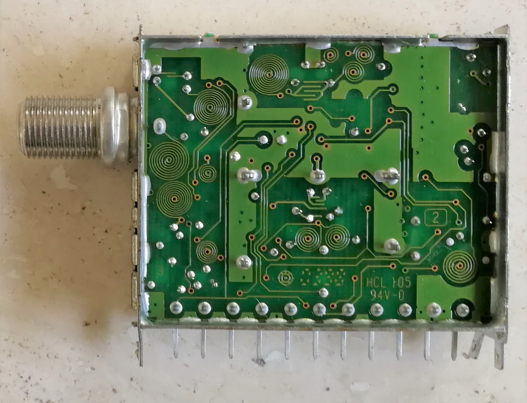
Wave soldering side of the Philips UV1336/AF-2. It was used for printed RF coils, saving some 10 hand insertion coils and creating more space on the B-side. [Pieter Hooijmans collection]
|
It has already been said before, but the WSP was only a mechanical and pin allocation standard. Once introduced, all standardization discussions came to an end and all tuner makers continued competing like before. Nothing happened in the field of electrical standardization (2B vs. 3B, I2C vs. 3W, 3-bit vs. 2-bit vs. inverted 3-bit VST, band edges, symmetrical/asymmetrical IF out, yes/no FM, CB or N-1 traps) and connectors, which even saw a growing diversity (phono, 4 different IEC and F lengths), while customers tried to force the different makers to provide compatible products to allow multi-sourcing. As a consequence diversity exploded. At the same time all this happened within the constraints of the 50mm WSP (UV1300) frame size and pinning. It was no surprise, however, that one day customers started to ask for functions that did not fit within the UV1300 frame size. For Philips this were the broadband splitter requested by the TV-VCR group of iR3 in Wien (Austria) as replacement of the UV1216D, and a switchable LNA requested by Chinese customer TCL (but discussions with BGTV were also ongoing). At the moment of requests (1997) these additional functions did not fit inside the 50mm frame, and it was decided to introduce a lengthened 65mm WSP frame.
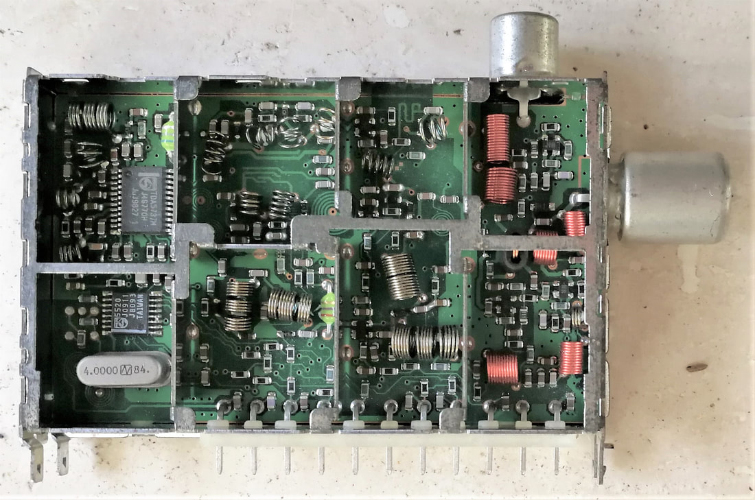
The Philips UV1316T/AI-(Mk2) tuner with broadband active loop-through. [Pieter Hooijmans collection]
|
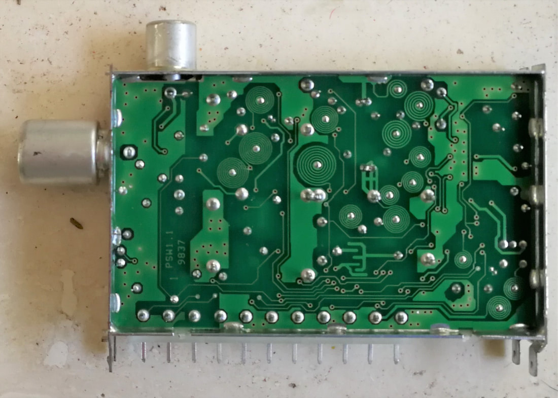
The solder side of the Philips UV1316T-Mk2. The lack of components on this side allowed for large ground planes for solid RF grounding.
|
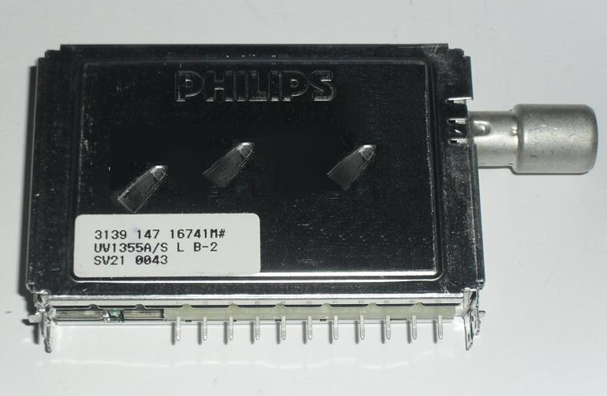
The new 65mm WSP frame of the UV1355A, which was strictly spoken not WSP because that standard only covered 50mm frames. Note that the pins have been pulled forward to be compatible with standard UV1300. Also note the long IEC connector (suffix B).
|
|
The UV1316T was a fairly straightforward design: the UV1316-Mk2 tuner with the PS1311 three-transistor active splitter in front of it. Although the amplifier to the tuner theoretically could have been deleted, it was not to reduce risk of project delays. Output of the splitter was through a phono connector on the top side of the frame.
The UV1355A had a switchable LNA between the antenna connector and the regular tuner input, to allow better reception of weak off-air signals, which especially in the larger China-South East Asia area still a major problem. In case of weak signals the LNA was switched on, providing an additional 10dB gain using a BFG540 amplifier as used in the TP900-Mk2. For larger input signals this obviously reduced the RF input TOP of the AGC, and therefore the LNA was switched off around medium level input signals. In case of large interferers it all became more complex, and ultimately had to be judged on what was the best picture. The TV watcher therefore controlled the LNA on/off setting through his remote control. By-passing of the LNA was done with the BF1007 MOSFET also used in the TP900-Mk2 passive loop-through. A third new function was the UR1316, the same functionality as the tuner section of the FR1200-(Mk2), i.e. FM radio reception as a fourth band. This tuner was a redesign of the tuner, albeit without the 33V DC/DC-converter and the TSA5523 PLL; the UR1316 used the standard TSA5520. Just like in the FR1200 for FM reception the VHF-Low band was reduced in bandwidth, while the IF was reduced to 10,7MHz. At the IF output a 10,7MHz filter took care of the signal filtering. None of these three tuner models immediately became a high volume product, mostly due to the intrinsically conservative TV design world. However, they each provided valuable features, which needed some time to be recognized. In the next generation UV1300-Mk3 they each would become broadly used concepts. Especially with the LNA and FM-radio function the BU Tuners was finally getting back into the position of leading tuner innovator, which it had lost with the introduction of the WSP UV1300-Mk1. |
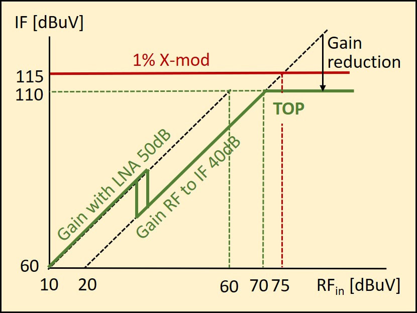
Gain and TOP diagram explaining the effect of a 10dB gain Low Noise Amplifier. It is only used for weak received signals, extending the tuner sensitivity by 10dB (from 20 to 10dBuV). But because it would reduce the large signal behaviour (TOP is reached 10dB earlier at 60dBuV) it is switched off (by-passed for larger input signals.
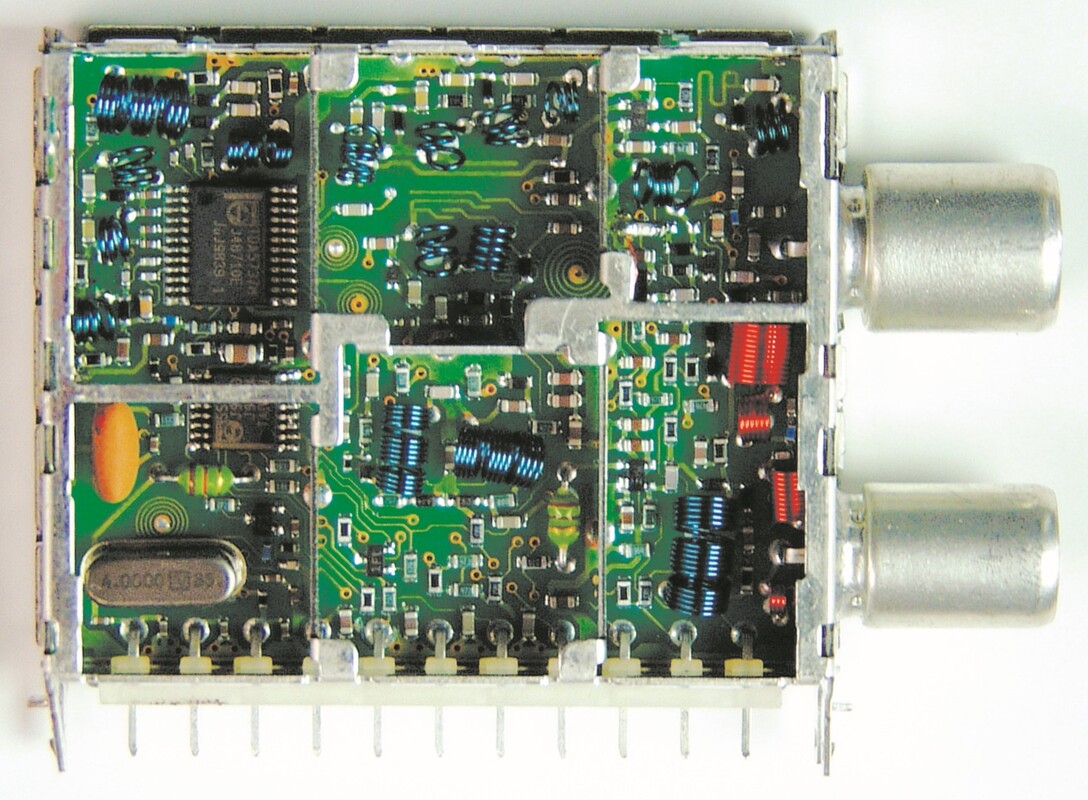
The Philips UR1316, member of the UV1300-Mk2 family. This tuner allowed FM radio reception, and can be recognized from the 2nd, lower IEC connector for FM as well as the orange 10,7MHz sound IF filter. [via Darko Jancin]
|
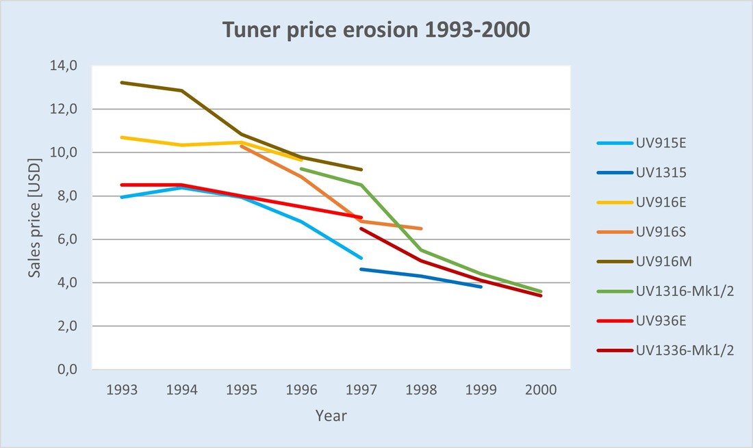
Graph showing the tuner sales prices (in USD) of the primary VST and PLL types from 1993 to 2000, showing the - for tuners - unheard of and dramatic price erosion.
|
With the UV1300-Mk2 the BU had re-established itself as the primary tuner supplier for the Philips TV group, although it had structurally lost some 25% volume to Alps and occasionally an opportunistic share of Samsung or other price fighters. As a net result the tuner volumes for Consumer Electronics (so the combined volumes of BGTV and Videq/iR3) between 1993 and 1998 remained flat at 13,5Mio units, albeit at the dramatic price erosion in this period of 60%. An average 16,5% price reduction per year! In 1998 alone the powerless BU management gave away 35% on its flagship UV1316-Mk2 price to BGTV. One of the (probably) positive side effects of all this was the demise of VST tuners, given that the price difference between VST and PLL tuners became negligible, see the graph. The family essentially reduced to the PAL-B/G UV1316, PAL-D/K UV1356 and NTSC UV1336, albeit with many sub-versions.
|
|
The only compensation for the price erosion was an increase of external tuner sales, from almost nothing to 7,3Mio units in 1998, although mostly at prices hardly better than the internal ones. Having obtained these dramatic price reductions for one of its most expensive TV components, the UV1300 was allowed back on the full BGTV range: the L7 (later versions and as replacement of the UV1300-Mk1) and L9 low end chassis, the A8 (only the US versions) and A10 mid end platforms, and the MG high end chassis from Brugge. Especially the MG chassis (for Matchline Global?) ran succesfully until at least 2001, with real flat square picture tubes, 100Hz Digital Scan with Digital Natural Motion picture enhancement based on the Philips Semiconductors Falconic IC and Digital Crystal Clear contrast enhancement. It also featured NICAM digital audio and 3D surround sound. It was the first time since the 1990 UV900 family that a tuner family was so consistently used across multiple BGTV chassis, and made the Mk2 a major business success.
|
A10E was the mid-end Philips chassis. Externally it ressembled the high-end Matchline sets, including the luxury stand as shown, but internally lacked the feature box, being based on the Mid-end One Chip TV BOCMA IC. This is the 28PW6515 from 2000.
|
|

The MG platform was very successful, with successive chassis featuring more and more functionality. This is the MG7.1 Matchline 32PW9525 from 2001. On the right is the large vertical feature box module, on the left an internal sub-woofer. On the left the frontal view, with a cabinet for VCR/DVD and STB, on the right the internal view [Obsolete Telly]
|
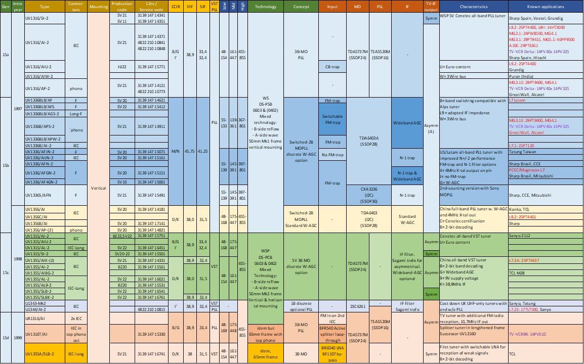
Overview of the Philips UV1300-Mk2 WSP tuner family. Although the number of basic types was substantially lower than the UV900 predecessor, the type diversity (unique 12nc's) has increased to almost 45.
Tuner Theory 14: Digital transmission
A major change in the way of transmitting (TV) signals was looming over the horizon: digital transmission and reception. Driven by the rapidly increasing IC integration capabilities this technology was introduced in narrow-band point-to-point communication for cordless phones and mobile phones as discussed earlier, but now also came to the broadcast domain. Without making it a university lecture, it is necessary to introduce the basics, especially those related to the receiver, and explain why we prefer digital transmission over the good old analogue form. What makes it better?
Analogue reception quality, as we've seen in all 5 chapters so far, is determined by the Signal-to-Noise Ratio (SNR) at the receiver: the noise level must be sufficiently small compared to the wanted signal to avoid we see or hear it. For TV reception the accepted SNR requirement is more than 57dB, both for noise and disturbances (X-modulation et cetera). In case the SNR degrades below this 57dB limit it will become increasingly visible, although for any good TV receiver the picture remains visible even for very large noise levels. We call this graceful degradation, an important characteristic and differentiator of analogue systems.
Analogue reception quality, as we've seen in all 5 chapters so far, is determined by the Signal-to-Noise Ratio (SNR) at the receiver: the noise level must be sufficiently small compared to the wanted signal to avoid we see or hear it. For TV reception the accepted SNR requirement is more than 57dB, both for noise and disturbances (X-modulation et cetera). In case the SNR degrades below this 57dB limit it will become increasingly visible, although for any good TV receiver the picture remains visible even for very large noise levels. We call this graceful degradation, an important characteristic and differentiator of analogue systems.
Digital transmission is based on a fundamentally different concept. The analogue source information is digitally encoded using analogue-to-digital converters (ADC), resulting in a stream of ones and zeroes. This digital bitstream is then used to modulate a carrier frequency in either amplitude (Amplitude Shift Keying, ASK), phase (Phase Shift Keying, PSK) or frequency (Frequency Shift Keying, FSK). Each of these modulation schemes can be used at different levels defined by the number of values the modulating signal can have. Binary modulation just swiches between two levels (e.g. On-Off ASK), Quarternary modulation switches between four levels (e.g. 4-phase 4PSK or QPSK). Most of these modulation schemes use coherent techniques, which means that both the in-phase (I) and quarternary (Q) complex axes of the RF carrier can be modulated. This modulation along the two axes is always represented using a constellation diagram as shown below.
Explanation of digital modulation using QPSK as an example. Upeer left is green is the input BIT-stream. Because for QPSK N=2 (2^2=4 different phases) the input bit-stream is cut into 2-bit SYMBOLS. The constellation diagram in the centre defines which RF phase belongs to each symbol. Note that QPSK is a constant envelope modulation, because the vectors of all four constellation point shave the same length. The resulting wave form, with changing phases at symbol transitions is shown lower left.
The diagrams on the right illustrate the receiver action: in a coherent receiver the incoming RF signal is mixed separately with 90-degrees shifted coherent I and Q local oscillators. The detected output signals are the purple I and Q data streams, which represent the components of the received signal along the I and Q axes. From these we recognize the symbols, which can finally be converted into the original bits.
On the receiver side in principle the inverse operation takes place: coherent detection. When the incoming RF or down-converted IF signal is multiplied (mixed) with a regenerated local oscillator signal of exactly the same frequency and phase, the mixer output will a signal proportional to the phase difference between the received signal vector and the LO signal vector. When this is done using orthogonal I and Q LO signals the two mixer outputs effectively measure the I and Q vector components of the modulated carrier vector. When the carrier has been modulated at the transmitter side, the receiver will thus retrieve that modulation. In the absence of disturbances this regeneration can be error-free, resulting in source-quality picture and sound.
The main difference between analogue and digital modulation now becomes important. Whereas in analogue receivers, as described above, noise will give graceful degradation of the SNR, in digital receivers noise will lead to wrong decisions when reconstructing the digital symbol and bitstream: Bit Errors. The amount of these errors per second is the Bit Error Rate (BER). In the received constellation diagram this is represented by a much wider Gaussian distribution of the constellation points. At the moment of decision taking the instantaneous signal vector should now be within the green 90-degrees sector to give a good decision. With decreasing Carrier-to-Noise Ratio (CNR) the BER rapidly increases according an exponential curve exp(-SNR). For most broadcast standards a maximum BER of 10^-4 is used as the threshold for good reception.
The main difference between analogue and digital modulation now becomes important. Whereas in analogue receivers, as described above, noise will give graceful degradation of the SNR, in digital receivers noise will lead to wrong decisions when reconstructing the digital symbol and bitstream: Bit Errors. The amount of these errors per second is the Bit Error Rate (BER). In the received constellation diagram this is represented by a much wider Gaussian distribution of the constellation points. At the moment of decision taking the instantaneous signal vector should now be within the green 90-degrees sector to give a good decision. With decreasing Carrier-to-Noise Ratio (CNR) the BER rapidly increases according an exponential curve exp(-SNR). For most broadcast standards a maximum BER of 10^-4 is used as the threshold for good reception.
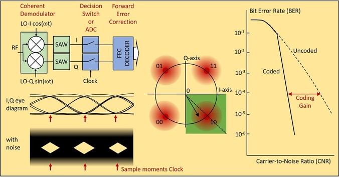
The principles of coherent demodulation and detection illustrated for QPSK. In case of noise-free reception the output of the demodulator and SAW filters (for noise minimization) is an open eye diagram as shown centre left. With a s synchronized Clock at exactly the right moments of maximum eye opening samples are taken, which will lead to perfect decisions on the detected signal. In case of (serious) receiver noise the eye diagram becomes as shown lower left, with much reduced eye opening. In the constellation diagram this is seen from the much larger and noisier constellation diagram lower left. With increasing noise the probability that the instantaneous vector is outside the green sector (for the example of symbol 10 as shown) becomes larger, leading to increasingly more wrong decisions. This results in the uncoded BER curve as shown. Using Forward Error Correction (FEC) coder and decoder a certain ratio of wrong decisions can be corrected, resulting in a coding gain.
Some final remarks on topics that will come back regularly when discussing digital receivers:
- As the picture shows, the BER curve, especially in case of coding, is extremely steep. 1 or 2dB CNR reduction gives a few orders of magnitude BER increase! Such increase does not result in a graceful degradation, but will quicky give highly annoying MPEG block errors or audio distortion.
- As the picture shows for the QPSK example, the formal decision for a received 1 or 0 is based on the phase of the instantaneous signal vector at the decision moment. Obviously receiver amplitude noise can push the vector away from its nominal value. However, the same will happen in case of phase errors, mainly due to Local Oscillator phase noise. Phase noise can be seen as resulting in a "shaking" I-Q reference grid, effectively reducing the green area. Or, equivalently, as a rotating constellation diagram, with the same effect. Furthermore, in case of multiple conversion steps the LO phase noises add up. In the digital TV tuner discussions we will thus regularly see low phase noise PLLs as being very critical.
- A similar phase error effect comes from I and Q LO signals that are not perfectly orthogonal, so 90 degreed out of phase. For a phase error of 1,3degrees the CNR implementation loss is 0,1dB, at 7degrees it is already 0,5dB. Many receivers will therefore implement an active control loop to maintain orthogonality.
- Yet another source for errors is any interference into the LO control signal: I2C crosstalk and microphonics are typical examples. Because the low phase noise of the LO requires a narrow PLL loop bandwidth, initially many of these effects are not filtered out, thus introducing LO phase distrurbances, potentially resulting in loss of lock. All digital channel decoders therefore contain a second Carrier Recovery PLL with a larger bandwidth than the tuner LO-PLL to eliminate these disturbances.
DVB-S Digital satellite TV Broadcast, 1993
|
After the formal demise of D2MAC and HDMAC in 1992 it was obvious that another solution was required. Since 1991 a substantial group of European companies had been discussing as European Launching Group (ELG), initially semi-illegal because the official European Broadcast Union (EBU) policy was still D2MAC. With D2MAC dead, by September 1973 the ELG was formalized into the Digital Video Broadcast (DVB) project under the EBU. The main purpose of DVB was (and still is) to propose standards to Cenelec and predominantly ETSI for formalization. As had been the case for D2MAC, the first application targeted was satellite broadcast, which became DVB-S and a first standard release in 1995.
Digital broadcast standards have - of course - a fundamentally different structure than the "good old" analogue standards. To start they use digitized video and audio as a source, in contrast to the CVBS analogue TV signal, the basic luminance baseband signal with colour and audio multiplexed on multiple sub-carriers. All first generations digital broadcast standards, be it for satellite-, cable- or terrestrial transmission, used the new MPEG2 standard (from the ISO/IEC Motion Picture Expert Group), the successor of the MPEG-1 coding used in the Video-CD. MPEG2 is a flexible and scalable coding scheme that uses interpolation and predictive coding to compress the coded digital stream to rate of 2-15Mb/s for standard video. Because a block of 12 pictures are jointly interpolated and coded this method is also called Block Coding. A block takes roughly 0,5s, which is then also the minimal lock time of a receiver. HDTV could be coded at 30Mb/s, while audio was scalable in steps of 64kb/s for higher quality or surround sound. From a broadcasters perspective MPEG2 had the big advantage that it could be combined with Conditional Access (CA) encryption to manage subscriptions, and that by varying the coding depth multiple MPEG2 streams could be stacked in one channel, thus allowing to vary the number of TV channels per RF channel depending on the service level provided by the operator. Up to here the MPEG2 Source Coding would be standard for all DVB versions, the Channel Coding optimized to the channel used.
Still common for satellite and cable was the first step, to provide as much as possible "white" data, without long strings of either ones or zeroes, and thus the energy spread as much as possible across the data bandwidth. These steps were: |
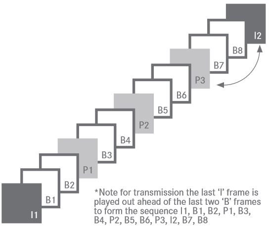
The MPEG2 video compression concept: I1 and I2 are so-called Intra Pictures, coded at full resolution; P1-P3 are motion-compensated Predicted Pictures; B are bi-directionally interpolated pictures. So B1 and B2 are based on (time-compensated) interpolation of I1 and P1. The first twelve frames shown form one block. [IABM Glossary]
|
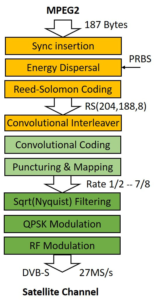
The DVB-S satellite upstream signal processing flow.
The QPSK symbol constellation diagram. Each symbol is coded by 2 bits, one In-phase (horizontal axis) and one Quadrature (vertical axis). [Wikipedia]
|
For satellite the channel characteristics are mainly power-limited: the travelling wave amplifier (TWA) tubes in the satellite perform optimal with almost constant amplitude low dynamic range signals, while on the receiver side the thermal noise of the LNB limits the SNR. Multi-path, echoes and tilt, in contrast, are absent and therefore not an issue. So the following steps are again targeted at decoding robustness at low SNR:
|
|
On the receiver side the first steps are essentially independent of analogue or digital modulation as long as the channel bandwidth remains the same. First the LNB block-converts the Ku-band received signal to an IF of 950-2150MHz, followed by a satellite front end that performs the second down conversion to 480MHz. In the first digital satellite systems this was still too high, and a third down-conversion to 70MHz followed. The next functions were required to pre-condition the still analogue IF QPSK modulated signal for the inverse digital processing of all the upstream steps: first I and Q (quadrature) demodulation to baseband, followed by A-to-D conversion. To guarantee sampling at the right time (so at the moment of maximal eye opening of the received signal) first the clock and then the carrier frequency required recovery in two PLLs. When both loops are closed the ADC outputs deliver the digital I and Q streams, which can finally be decoded into the original MPEG2 transport stream. This collective operation is usually referred to as the Forward Error Correction (FEC), which is followed by descrambling (conditional access) and source decoding (demultiplexing and extraction of the wanted channel from the MPEG stream. In the first generation DVB-S systems each of these functions was performed by a dedicated IC, later followed by increasingly integrated solutions.
Digital satellite, as the successor of the analogue FM DBS, exclusively used CA (subscription) set top boxes, and discussions about DVB-on-TV were irrelevant. Because of the major advantages for the operators roll out of DVB-S was extremely fast. Already in November 1994, so well before the first formal setting of the DVB-S standard in September 1995, Astra-1D was launched on top of an Ariane-4 rocket, the first satellite to broadcast some digital satellite channels. Astra-1E (October 1995) and -1F (April 1996) were already exclusively broadcasting DVB-S. In parallel the same happened in the US, where especially Hughes Electronics, then still part of General Motors, launched its DirecTV digital satellite service June 1994. Other US operators were Echostar and Primestar, the latter was acquired by Hughes/DirecTV in 1999. The US systems essentially used the same standard as DVB-S, albeit with slightly different settings and called Digital Satellite System (DSS). |
The DVB-S downstream (receiver) signal processing flow.
|
How was Philips playing in all this? With good foresight of the digital broadcast revolution that was coming, in 1993 a new Business Group was created, Business Electronics, which had as main Business Unit Digital Video Systems (DVS). It assembled a number of design centres and sites of declining or forgotten businesses: headquarters were in Eindhoven, where Consumer Electronics resources were collected in a new Digital Systems Lab. STB design was in Suresnes (France, the former TV development) and production in Hasselt (Belgium, formerly part of optical recording), while the Louviers (France) business continued to focus on Single Master Antenna TV (SMATV) headend solutions for cable or large in-building distribution. Having missed out on the first generations analogue DBS STB the new organization went all out on the DVB-S and DVB-C (cable) STB. For once Philips was again a main player in a new application, and the first generation satellite STB was released in 1995. (In these applications the STB was also often called the Integrated Receiver Decoder (IRD)). In 1996 sales were already 165MioHfl, still at heavy but accepted losses, delivering integral solutions (both headends and boxes) for Canal+ and Astra in Europe, and major new contracts for Brazil and Malaysia (Measat). (But note the difference: these STB were not sold under the Philips brand, but as ODM to the operators!) The next five years the Philips BU DVS grew to 1,6Bio€ by the year 2000, a CAGR of 75%/year! By that time the world-wide STB market (satellite plus cable) had a size of 10Bio$, with the satellite share 23Mio sets per year: 12Mio in Europe, 8Mio in the US and 3Mio in Asia. Philips had become the #2 global player with a 14% market share, behind #1 General Instruments (which only played in US Cable market) and #3 RCA/Thomson (the number 1 in US satellite with DirecTV). Not a bad achievement.
Philips Semiconductors in parallel released complete chip sets for satellite (and cable) STB, which will be discussed in the coming sections. By the year 2000 Semiconductors claimed a #1 position in satellite RF ICs with 66% market share, and 30% share in the channel decoder market.
Philips Semiconductors in parallel released complete chip sets for satellite (and cable) STB, which will be discussed in the coming sections. By the year 2000 Semiconductors claimed a #1 position in satellite RF ICs with 66% market share, and 30% share in the channel decoder market.
SD900 & QP1200, the first digital satellite frontends, 1994-1998
Almost as soon as D2MAC was nearing its end, and even before the formal launch of DVB-S, development of digital satellite receivers started. Where all players had to find their way in a new and unexplored domain, it was the first time that broadcast signals in their entirety were being digitized. One of the main challenges, especially with lower bitrates, was the integral receiver phase noise which determined the accuracy of the digital demodulation and detection. Philips worked together with three early players in the digital satellite market: Scientific Atlanta in the US, NTL/Pace (UK) and Philips DVS Suresnes in Europe. (NTL was a development lab spun out from the BBC, working for the UK company Pace to develop the new DVB-S system). When defining the first DSS/DVB-S systems a number of elements played the key role in the choices made:
- availability of the necessary new ICs. The most relevant players for the Philips solutions were California-based VLSI, an aggressive start-up player that had in 1994 also acquired the company Comatlas (Rennes, France) playing in the digital satellite field; LSI Logic, which was used by the Philips DVS organization in Suresnes, and of course Philips Semiconductors. Each had their own chip architecture and especially interfaces, requiring at least initially different tuner/front end solutions;
- the choice of bitrates. The DVB-S standard supports bitrates between 1Mb/s and 45Mb/s, a very large range, at least for the first generation receivers. In practice this was often split in low bitrate 1-15Mb/s for "professional applications" and 15-45Mb/s for consumer video distribution;
- interfacing, or where to put the boundary between the tuner/frontend module within the complete receiver. This could be the IF output, the down-converted I/Q baseband signals or even the complete FEC.
|
When the BU Tuners was trying to define first products for DVB-S, the first issue encountered was the choice of IF. Available FEC chips could not handle the classical 480MHz IF used in FM satellite receivers. The first solution was therefore the Satellite Tuner ST1200. Instead of 480MHz it provided 70MHz as IF output, using a second down-conversion. Apart from buffering no further functions were added, and SAW filtering and demodulation were done outside the can. (Therefore it was not a frontend). The first version was the ST1234, with the reduced input frequency range used in the US, followed by the ST1216 for European systems. Although the solution sounds simple and obvious, the ST1216, with its two oscillators, had many problems in production with harmonics and beats of the IF.
The ST1216 was intended to be used with demodulators like the Philips Semiconductors TDA8040 Quadrature Demodulator (QDM, made in a 2um bipolar technology), which worked in combination with the TDA8041 Controller (QDMC, using a 1um bipolar technology). For the quadrature demodulation of the QPSK signal the TDA8040 VCO required in-phase and 90 degrees rotated quadrature LO signals, which were obtained through a VCO at double the frequency followed by a divider. The proper demodulation of the QPSK constellation, which has a natural 4-fold phase ambiguity, required a carrier recovery PLL, which was part of the TDA8041 controller. In principle either the VCO2 in the ST1200 tuner or the 8040 VCO could be used for the carrier recovery PLL, but the tuner VCO had a larger range and was default used. Before the carrier recovery loop could lock, the clock recovery loop needed locking first, because the digital data stream was required to solve the constellation ambiguity. This VCO needed to tune across the full symbol rate range of 1-30 (initially) and 1-45MHz (later generations). Because for the PLLs not only the data at maximum eye opening but also during the zero-crossings was required, also this VCO operated at twice the symbol rate. The 3-bit A-to-D converters for the I and Q signal streams thus also sampled at twice the symbol rate. This solution, although more than sufficient for the first generation, still had a number of limitations:
|
Block diagram of the Philips ST1216 and ST1234 satellite tuners for DVB-S digital satellite.
First generation satellite channel demodulation using the Philips ST1216 tuner plusTDA8040 QDM and TDA8041 QDMC. [Philips Semiconductors Application Note AN95053 "QPSK/BSK demodulator chip set", March 1995]
|
The second path of digital satellite front ends was therefore different in several aspects. First, mainly to have sufficient space for adding the new functions, the SF900 was used as a the basis, despite its larger size and not having horizontal mounting as an option. And instead of a tuner with a second down-conversion, the SD900, as it was called, used the Plessey SL1710. This IC had the same functionality as the Philips TDA8040 but supported input frequencies up to 500MHz in stead of 150MHz. Based on specifications of NTL a frontend was designed for Pace IRDs, the SD956E. Because of the overall better phase noise behaviour (the whole signal chain contained one mixer-oscillator stage less) this solution could be used for symbol rates down to 1MS/s. Because the systems had to cover variable symbol rates up to 30MS/s all symbol rates used the same 36MHz SAW filter. Nyquist filtering only took place in the FEC IC. This meant that at 1MS/s symbol rate and a CNR of 8dB (required for a 10^-4 BER) the SNR within the 36MHz IF channel bandwidth was -7dB! Some 100.000 of these frontends were sold to Pace.
Block diagram of the Philips QP1200, the first commercial DVB-S full satellite channel decoder board. [Philips QP1200 product leaflet, February 1995]
The Philips QP1200 satellite channel decoder board. In front the ST1216, behind it the two SAW filters. In the centre the TDA8041 is visible, upper right the VLSI IC (still not released at the time the picture was taken). [Philips QP1200 product leaflet]
|
The biggest customer in this phase was the internal Philips DN-DVS group in Suresnes. For their first generation STB/IRD, which never passed beyond the prototype stage, a modified frontend was derived from the NTL SD956, the SD926E. However, for the real first product platform G+1 they switched to the QP1200, the complete channel decoder function from RF to MPEG-2 transport stream. It was essentially an application board of the ST1216, the TDA8040-8041 and a VLSI FEC IC. The QP1200 supported two fixed bitrates of 6 and 27,5MS/s, requiring two switchable SAW filters (of which the bandwidths are not known, but assumed to be 18 and 36MHz).
Because the form factor of the board didn't fit into the Krefeld production flow it was sub-contracted to the Philips Kentie pilot fab on Strijp-S in Eindhoven. The sales price of the QP1200 was 300DM, a price unheard of within the BU Tuners! However, Suresnes was very happy with the performance, and QP1200 was produced throughout 1996 - albeit with quite some problems, it was a steep learning curve - for the first generation boxes. A very valuable learning exercise for the BU! With respect to learning in this new domain of digital products two examples. One of the requirements of NTL on the SD956 was, probably based on some earlier bad experiences, resistance to micro-phonics. This was not a standard test, but it was finally agreed that the products would sample-wise be tested by using a drop-tube through which a wooden bullet was dropped from one meter on an operational SD956. When the system remained in lock the tuner passed the test. Secondly, on the QP1200 one of the specifications the BU had to accept was a guaranteed Bit Error Rate (BER) at a given input power. This required almost 12 hours testing, which meant that every day a dozen QP1200's was running all night to perform that analysis. Obviously this requirement was dropped on all future products. The next Suresnes generation G+2 dropped the expensive QP1200 board, but continued to use the ST1216, while switching to LSI FECs. By this time the BU Tuners had learned enough to be able to define the first real volume product, the SD1200. |
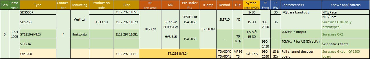
The first generation mostly low volume Philips digital satellite modules. Note that this overview lists three different type of functions: frontends (SD900), tuners (ST1200) and channel decoder boards (QP1200).
SD1200 Digital Satellite Frontends, 1996
|
By 1995 the system requirements for satellite IRDs was sufficiently stabilizing to allow the BU to develop the first real volume product for this new segment: the SD1200. As the name indicates, it re-used the SF1200 platform and for the tuner section all its key components. The BU was pushing its Semiconductor colleagues for an integrated mixer-oscillator IC, the TDA8010, but this device was encountering serious development problems, and was not available at the start of the SD1200 development June 1995. (It was eventually introduced in the SF1200-Mk2 as discussed earlier). The SD1200 essentially copied the SD956 solution with the Plessey SL1710 I/Q-demodulator IC, which had proven to be very reliable. In the meantime, most receiver systems moved to variable symbol rate solutions, initially covering the full 3-30MS/s range, although the lower symbol rates were hardly used and the symbol rate then reduced to typically 20-30MS/s. The consequence of these variable rate receivers was that SAW filters could not be used as channel filter, and integrated variable bandwidth filters were used instead. The SD1200 therefore only contained a wide SAW filter that acted as band limiting filter.
|
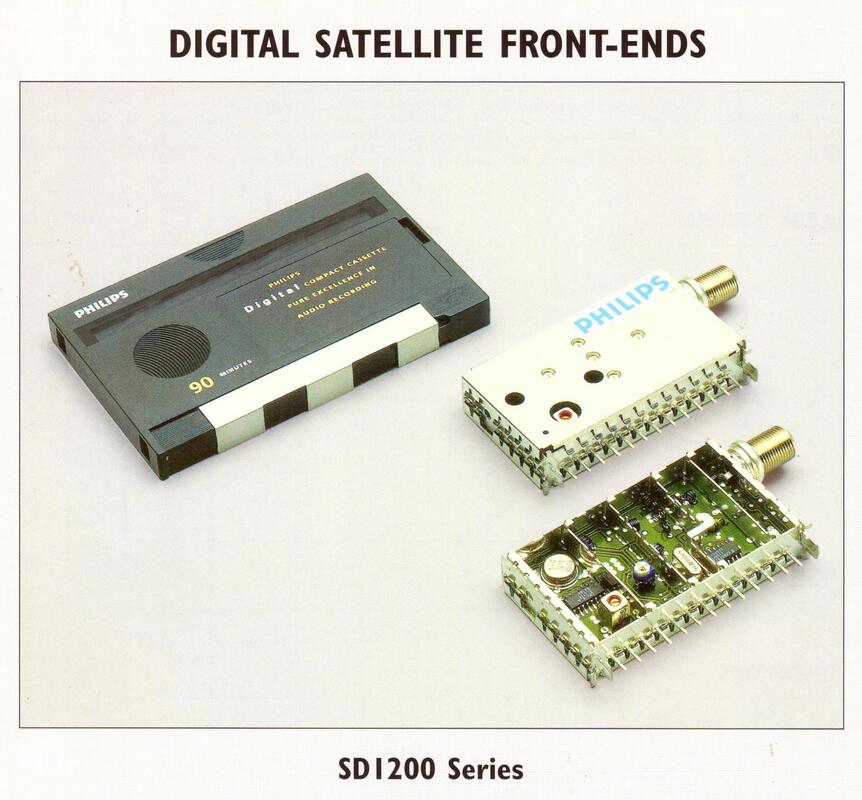
Publicity picture of the Philips SD1200 DVB-S front end. Which is highly interesting, because the frontend is compared in size with a Digital Compact Cassette, one of the unsuccessful and short-lived Philips innovations. [Philips Components SD1200 Product leaflet, February 1995]
|
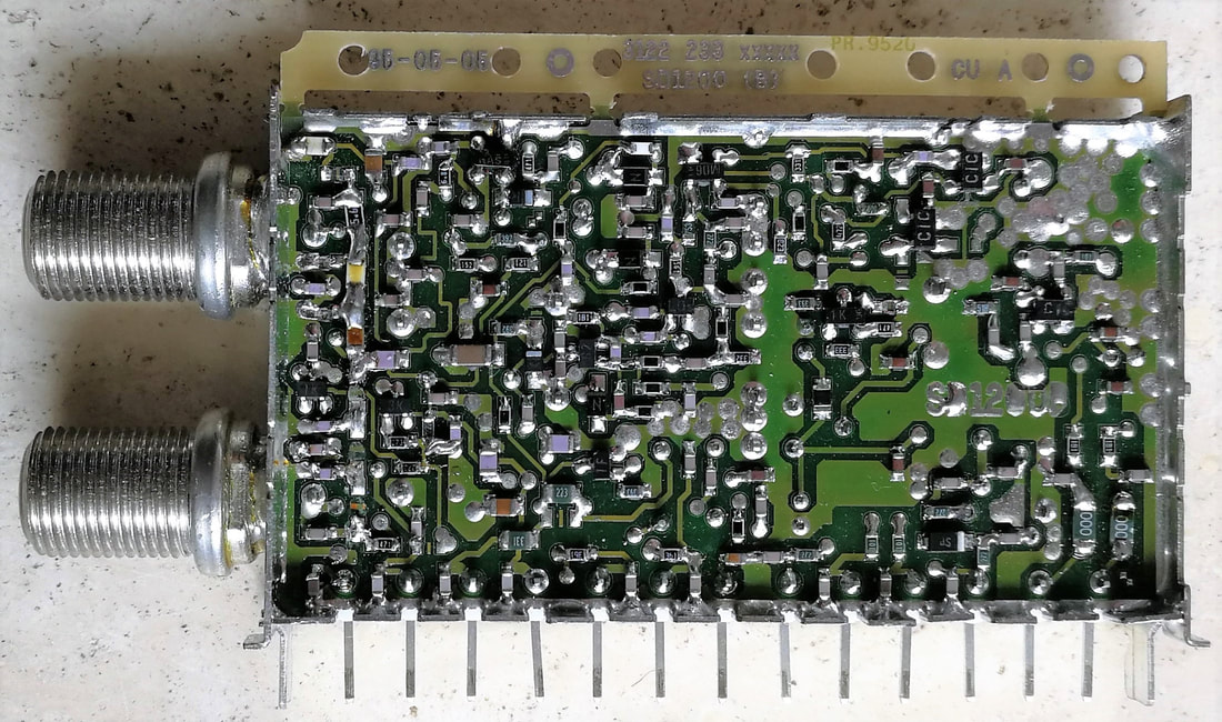
Pre-production sample of the SD1228C DVB-S satellite frontend, with dual RF input. Note the top-strip still attached, this would be broken off during the final production stage. [Ronald Dekker]
|
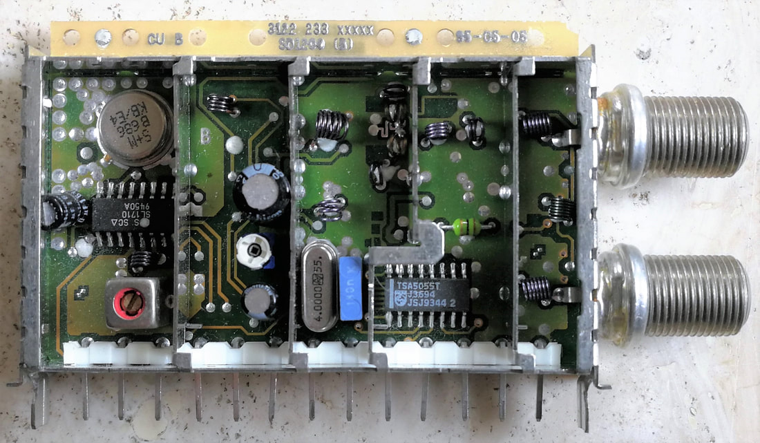
B-side of the Philips SD1228C. The two ICs TSA5055 PLL and SL1710 down-converter are clearly visible. All other RF functions are still discrete. [Ronald Dekker]
|
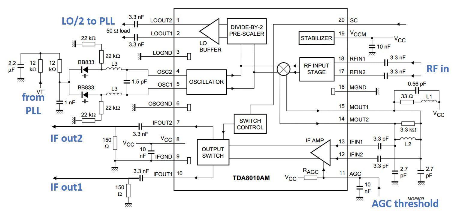
Block diagram and application circuit of the Philips Semiconductors TDA8010 satellite mixer-oscillator. [PS Data Sheet October 1996]
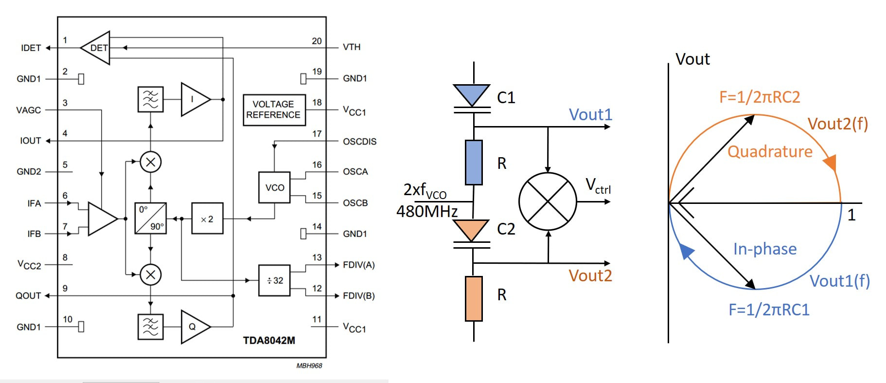
The Philips Semicondustors TDA8042 IQ-demodulator and its wideband phase control mechanism to keep the output voltages as close as possible to 90degr phase difference. The output of the IQ mixer Vctrl, which should be zero, was used to adjust the varicap voltages.
|
Rather quickly after the launch of the SD1200-Mk1 the next generation was developed, driven by performance and cost pressures. Compared to the Mk1 it made a number of steps:
|
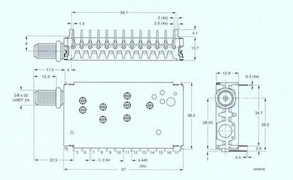
Mechanical outline of the SD1200. [Philips SD1200 Product Leaflet 1995]
|
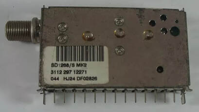
Picture of the Philips SD1268/S-Mk2 DVB-S front end. This had an extra wide IF BW of 39,5MHz and was used for the Measat IRDs, part of the big project Philips won for the DVB roll-out in Malaysia.
|
A last type of the SD1200-Mk2 family was the SD1278P, specifically for low symbol rate applications. Because for these systems the TDA8010 did no meet phase noise requirements, only the mixer section of the IC was used. It used an external low noise oscillator, with the signal injected into the TDA8010 oscillator tank circuit pins. Secondly it used the special low phase noise Plessey PLL SP5658, with as consequence that the tuner was not I2C but 3-Wire bus controlled. [This was probably the last time a GEC-Plessey IC was used by the BU, because in 1998 this company was sold to Mitel Semiconductors from Canada, becoming Zarlink in the year 2000. In the meantime most RF-IC activities were discontinued. This ended 15 years of cooperation.]
The SD1200-Mk1 and Mk2 were quite successful, riding also the wave of success of the Philips DVS IRDs. The DVS approach was to develop a STB/IRD platform, which then had an "open" commercial product (e.g. the STU5000 in 2000) which served only Free-to-Air satellite services. For each main operator customer a special version with specific Conditional Access (CA) was then derived, that only worked in combination with the smart card of that operator. On request they could receive modest cosmetic modifications. The satellite frontend volumes increased to a level of 3Mio units per year in 1999-2000, in these years roughly the same volume as the FI1200 multimedia frontends.
The SD1200-Mk1 and Mk2 were quite successful, riding also the wave of success of the Philips DVS IRDs. The DVS approach was to develop a STB/IRD platform, which then had an "open" commercial product (e.g. the STU5000 in 2000) which served only Free-to-Air satellite services. For each main operator customer a special version with specific Conditional Access (CA) was then derived, that only worked in combination with the smart card of that operator. On request they could receive modest cosmetic modifications. The satellite frontend volumes increased to a level of 3Mio units per year in 1999-2000, in these years roughly the same volume as the FI1200 multimedia frontends.
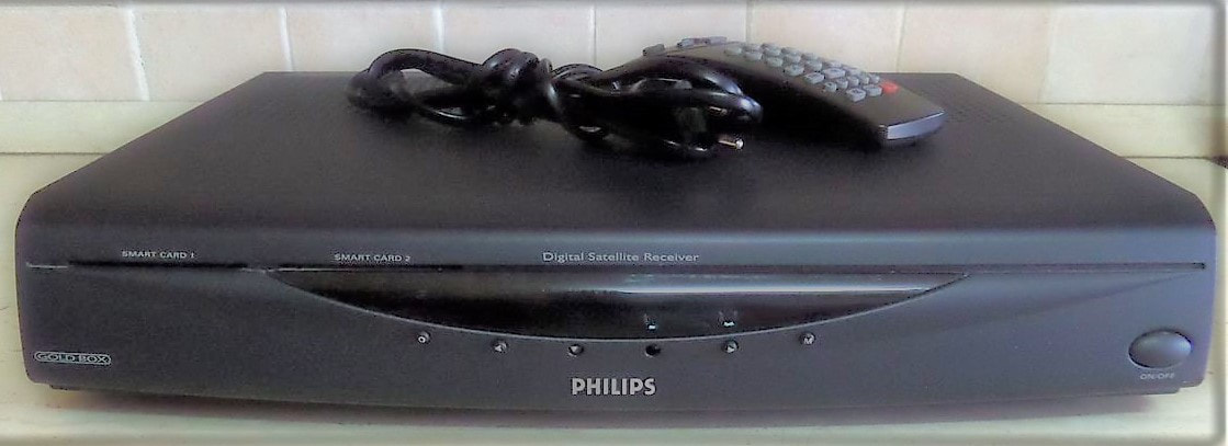
Two pictures of the STB design using the SD1200-Mk2. On top the DST5816 from 2000, below the DSX6073 from 2001. Both were versions for the Dutch CanalDigitaal conditional access system.
|
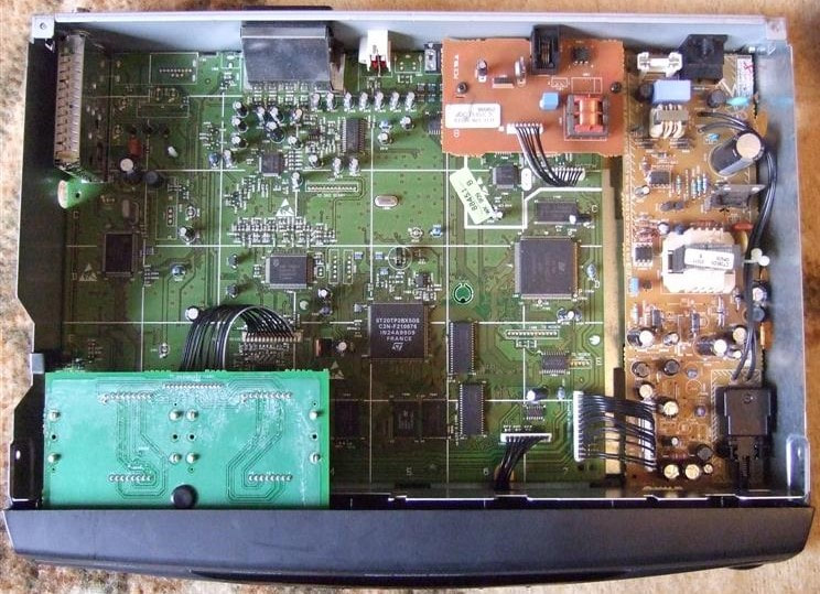
Interior view of the DSX6073, with upper left the SD1200-Mk2 digital satellite front end. These boxes were at this time produced in Hasselt, Belgium. [GbC-Net Froum]
|
Overview of the Philips SD1200 and SD1200-Mk2 DVB-S digital satellite front ends.
LNB microwave modules, 1995-1998
By this time, around 1995, the satellite market became well established in Europe, with Astra as the dominant player, and the LNB function well defined. This led to a number of market drivers for the 2nd generation LNBs:
- strong competition and price erosion. On the one hand the STB market remained much smaller than the TV segment. With at least 10-15 players everybody was fighting for enough volume, which lead to much price erosion but also regularly competitors stepping out or falling over. Also for Philips cost reduction became a very important element;
- the need to have a similar function as the dual but now also for the two bands;
- other continents, countries or regional service providers started satellite networks too, often based on Astra system specs if not by Astra/SES itself. Although there was consequently high commonality, local frequency bands or polarization could be different, requiring dedicated products;
- so far Philips had offered its LNBs in two colours, black or dark grey. More colours were not desired due to the logistical consequences. However, customers increasingly wanted their own design, either in form, colour or printing of the LNB housing, e.g. to match it with the dish.
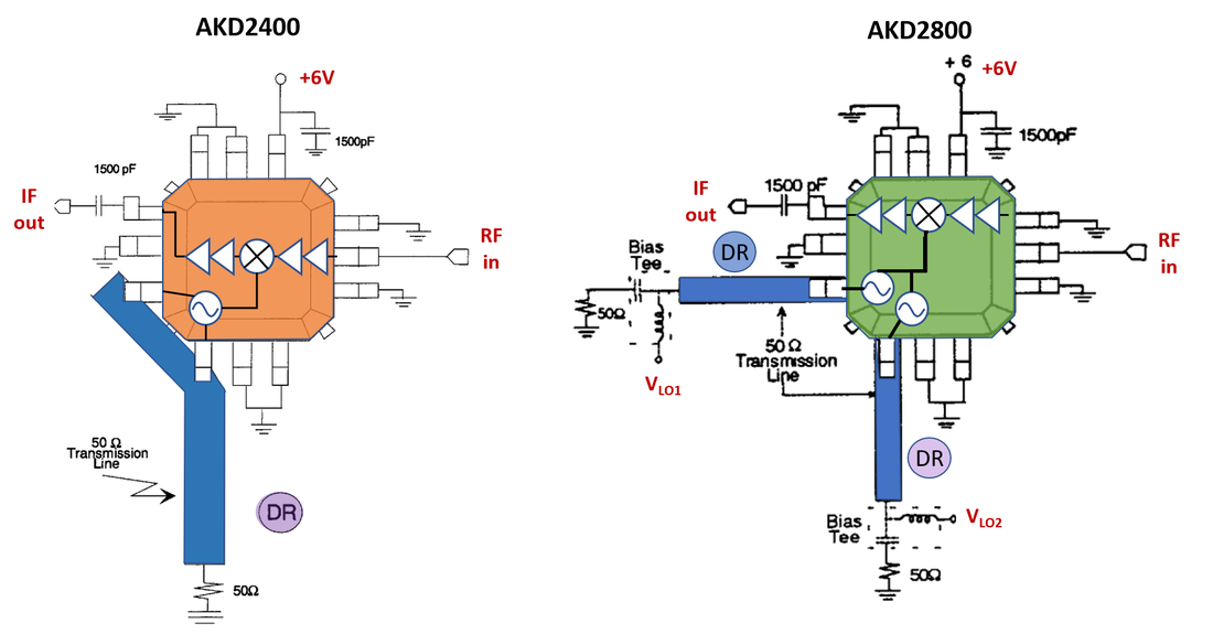
Application diagrams of the Anadigics AKD2400 (left) and AKD2800 (right). DR are the DRO resonator pills which couple to the blue 50 Ohm transmission lines. In the AKD2800 the oscillators are switched with the voltages VLO1 and 2 on their resonator input. [Anadigics AKD2400 and AKD2800 data sheets, 1995]
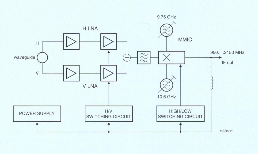
Block diagram of the Philips SC819TB Universal Astra LNB, introducing the new AKD2800 MMIC. [Philips Components SC819TB product leaflet, February 1995]
|
With respect to cost reduction of the electrical bill of material there were clearly two focus points: the HEMTs and the GaAs MO-IC, both costing multiple dollars. Although replacing the LNA HEMTs by cheaper components would remain a faraway target, the 3rd amplifier stage became possible with the introduction of the Siemens Grounded Emitter Transistor (SIEGET). This transistor was made in an advanced silicon bipolar technology with 25GHz fT, allowing it to be used up to 12GHz. As said, the pre-amplifiers stayed with HEMTs, although the supplier successively changed from Hitachi to Mitsubishi and finally NEC, all from Japan. The GaAs MO-IC was more difficult to replace, and for single-band functions the original AKD2400 continued to be used. However, this IC suffered from mayor stability and manufacturing yield issues, and multiple re-designed versions were introduced over the years, some as Philips-exclusive versions. For triple band designs a cost reduction was achieved by using one IC with switchable LOs, the AKD2800. It continued to use a DRO. Similarly, the AKD2820 and 2840 provided two signal paths in one package.
The product introducing this concept was the SC819TB, the successor of the SC817TB, which also introduced another innovation, the LNB module. In order to deliver functional LNBs to customers that wanted a proprietary housing, the LNB function needed be provided as a module. The LNB therefore had a complex and expensive "double housing" construction. First the Teflon PCB, after SMD onsertion and soldering, was sandwiched between two mechanical frame elements that were tightly screwed together. The functions of this module assembly were multi-fold: mechanical support for the non-rigid Teflon PCB; mechanical stability for the LO tuning resonator, also to avoid post-assembly mechanical stress as sometimes experienced in the old construction; massive grounding up to KU-band frequencies; and finally shielding to avoid Cenelec approbation problems. Because the frame to which the LO tuning screws were fixed was now much bigger, mechanical and temperature stability of the LOs also improved. |
The new, simplified outer housing of the Philips SC819TB. Note that the number of flange fixation holes has been doubled.
|
Exploded view of the SC819TB, clearly showing the new internal modular construction, resulting in a much-simplified outer housing. [Philips Components SC819TB product leaflet, February 1995]
|
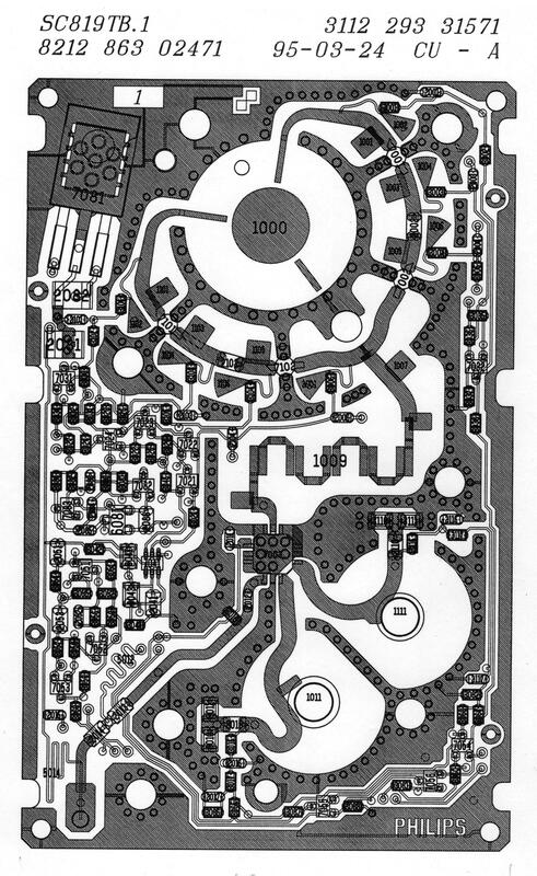
Lay-out drawing of the SC819TB Mk2. Some 10 degrees skew of the probes is visible. On the circular track around the waveguide the two times two HEMTs are visible. Also, the single AKD2800 MMIC with its two separate oscillator inputs.
|
Based on this new concept several products were developed. One sub-family was a series of LNBs (single, duals and twins) developed for the Measat project. Philips Digital Video Systems (DVS), the group within CE focussing on digital TV and satellite broadcast, had won a major contract with the Malaysia-based Measat group for delivering digital consumer equipment, both the STB and the outdoor unit. Although they used the same frequencies as the original Astra band, the required skew of 15 degrees meant that each Measat LNB was a new PCB design. [Skew is the effect that the signals from a satellite that is not seen directly south come under an angle. For optimal reception, while keeping the LNB vertical in its frame, the waveguide probes then need to be "skewed" with the same angle.] Measat 1 and 2 were both launched in 1996.
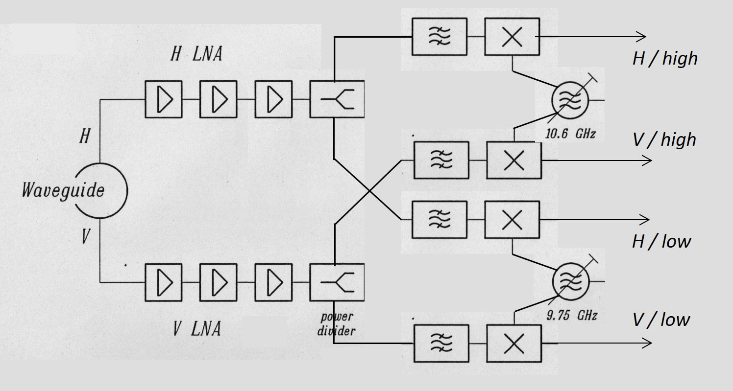
Block diagram of the Philips SC519Q Quatro LNB. Each Mixer MMIC had its own oscillator, which shared the dielectric resonator LO with the adjacent MMIC, thus guaranteeing they used the same frequency.
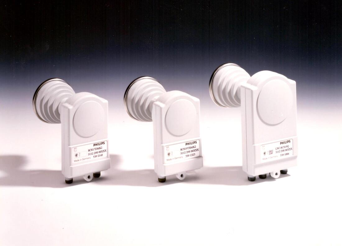
The three new Philips LNB core models. From left to right the SC817D-Mk2, SC819TB and the SC519Q. The larger house of the Quattro is clearly visible.
|
The other development was the Quattro LNB, essentially an extension of the original Astra dual LNB. Given the introduction of the Universal Astra concept, covering both H and V polarizations and low and high band, SMATV systems for in-building video distribution now needed four outputs to simultaneously receive all combinations. The Quattro was a complex product, and the design went through several product versions until the Mk3 was finally stable and reliable. The design was based on an architecture with two common oscillators, one 9.75GHz for the low band and one 10,6GHz for the high band). The outputs of the pre-amplifier branches and the DRO outputs were then each split and all four combinations applied to four AKD2400 GaAs mixers. The first Mk1 version suffered from high cross-modulation and high current consumption. It was re-designed into the Mk2, but this one suffered from problems with high power supply voltages. As said the final Mk3 solved all this. One of the measures was to put two GaAs ICs, which were the main reason for the high power consumption, in series for DC, thus reducing the total module current by almost halve. This of course required a floating ground of the upper mixer, but this was solved with RF grounding using interdigital capacitors. In the meantime, the product had gone through some confusing name changes (SC519Q to SC819Q and back to SC519Q), it had switched to the new internal module concept, and an extra pre-amp stage using the SIEGET BFP405 was added to provide cheap extra amplification. In the final architecture the AKD2400 were again used, four of them, which pairwise shared the same DRO pill to guarantee they operated at the same frequency. The Quattro required a larger housing, and was initially also available as a Quad, i.e. a Quattro followed by a 4x4 switch matrix, the equivalent of the 2x2 Twin LNB. There was also a real Universal Astra Twin, the SC517DS, with two outputs.
|
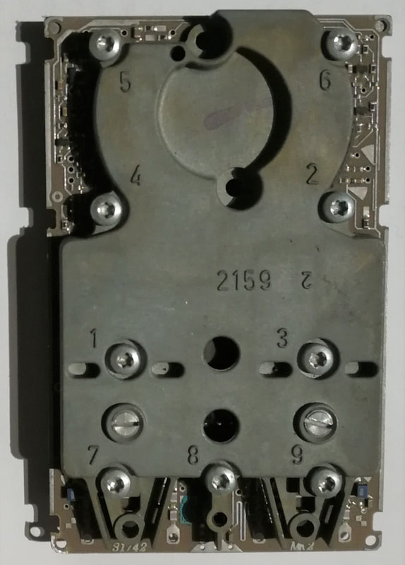
The inner module of the Philips SC519Q Quattro LNB. The modules are still made from Zamac. [Pieter Hooijmans collection]
|
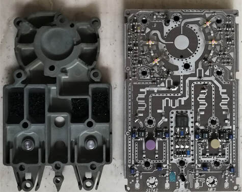
The opened Philips SC519Q Quattro module, showing the RF circuitry. Around the waveguide area are on each side the 2 HEMTs and the new SIEGET bipolar transistor. Wilkinson splitters guide the signals to the four BPFs and GaAs mixers, which share pairwise the DRO resonators. Note that the RF connection from the left branch to the 2nd BPF on the right uses the backside of the PCB. [Pieter Hooijmans collection]
|
With the SC500 family of twins, quads and quatros the Philips LNB business had now the full portfolio of LNB functions that were required to cover the full market. Apart from that, the technology platform had become mature, such that the different building blocks were stable, could easily be mixed and matched, and allowed a fast development time. Production flow was as much as possible optimized and automated, with minimal manual labor, allowing still profitable European production. Also, major cost savings had been achieved, although this remained the single biggest challenge: market price reduction went at least as fast, if not faster. The LNB segment, despite its aggressive cost reductions, would therefore always remain marginal on profitability. But the extension of the BU Tuners into the microwave LNB market was a considerable achievement, given the minimal technology compatibility with all other BU products. Also keeping in mind that all products presented here were developed by a small team of just three electrical and one mechanical designer!
Overview of the 2nd generations Philips LNB satellite receiver modules. They all used the same technology of an inner module that sandwiched the PCB, with a metal outer housing.
MVDS 40GHz microwave modules, 1997
In parallel to the LNBs other microwave applications emerged: Multipoint Video Distribution System (MVDS) and Local Microwave Distribution System (LMDS), operating at 40 and 29GHz, respectively. These systems were considered as alternatives for regions without good or local TV distribution systems, be it satellite or cable. MVDS was driven by Swisscom (Switzerland), where one transmitter would irradiate 4-5 villages, covering some 5000 subscribers. LMDS was focusing more on Latin America, countries like Venezuela, Costa Rica and Panama were mentioned. The system was internally promoted by Philips Broadband Networks (PBN) from Hazel Grove, south of Manchester. (This was a site that was acquired from GEC in 1961, containing the microwave activity as well as a 6" power semiconductor fab, still operated today by Philips/NXP spin out Nexperia).
|
MVDS and LMDS both operate in the microwave Ka band and each had a 1GHz wide low and high band: LMDS between 27,5 and 29,5GHz, MVDS between 40,5 and 42,5GHz. A flexible architecture was designed, see the block diagram, allowing a single lay out of the main board containing the LO, mixer and amplifier. The LO was operating at roughly similar Ku-band frequencies as the LNBs, between 13,25 and 14,5GHz depending upon the standard and band. To obtain the LO for the first microwave down-conversion this LO signal was doubled in frequency using a HEMT in its non-linear operating mode. Using this 2xLO frequency the LMDS signal was immediately converted to the standard 1-2GHz IF for a SF1200 front end.
|
Block diagram of the combined LMDS and MVDS microwave receiver. Black outlined blocks are common, green is MVDS and blue LMDS. Frequencies for each version are given in the table.
|
Picture of the Philips MC800 MVDS/LMDS main board, with the different functional blocks and components indicated.
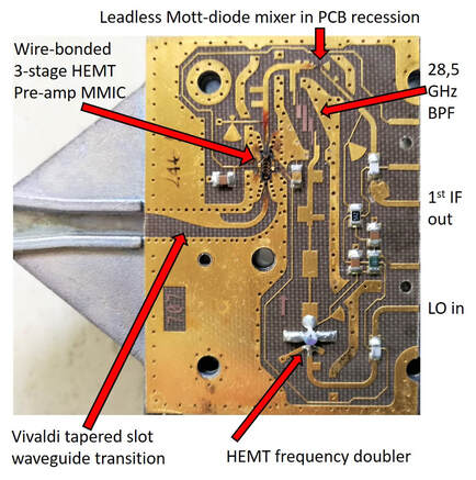
Picture of a Philips MC840L MVDS 40GHz front end tile, with the different components and functions indicated.
|
MVDS, operating at a substantially higher frequency required an additional down-conversion. The 1st IF output of the microwave mixer was of roughly the same Ku-band frequencies as in LNBs (12-13,5GHz) and used the LO signal to convert it down to the same 1-2GHz 2nd IF. The main board had a common lay-out for all four versions (LMDS/MVDS, Low/High-band), by leaving out SMD components the proper version could be assembled. It re-used most of the then latest LNB technologies: NEC HEMTs, Siemens BPF405 bipolar transistors, a discrete DRO (with <-90dBc/Hz at 10kHz), a discrete bipolar mixer. In contrast to the LNBs the IF amplifier was AGC controlled due to much large dynamic range of the terrestrial transmissions, using an opamp controller and four PIN diodes. All mounted on a standard o,5mm Teflon PCB. The microwave front end tile was a bigger challenge, handling frequencies between 26 and 40GHz. It contained next to the mentioned frequency doubler a Mott diode mixer (essentially an improved Schottky diode with a much lower C(V) dependence) and a 3-stage pre-amplifier die. The lead-less mixer diode was mounted in a laser-cut recession in the PCB, assuring that the contacts were level with the PCB metal tracks. Epoxy dots were applied for contacting. The pre-amp was a 0,2u HEMT amplifier from Philips Microwave Limeil (PML) in Limeil-Brévannes (south of Paris near Orly airport), a spin-off of the co-located Laboratoire Électronique Philips (LEP), the French Philips Research lab. It was wire bonded to the 0,25mm thick Duroid microwave PCB, which was assembled by PBN. The overall Noise Figure that was achieved was a remarkably low 1,7dB. Finally, a broadband Vivaldi tapered slot antenna on the PCB provided a proper matching to the microwave feed horn. The two PCBs were mounted between two Zamac covers, and the entire assembly mounted in a large plastic horn to protect it from the elements. Production of the module cost around 180DM at the time, so the modules were probably sold for anywhere between 250 and 300DM (150USD), making it the most expensive product ever produced by the BU Tuners.
|
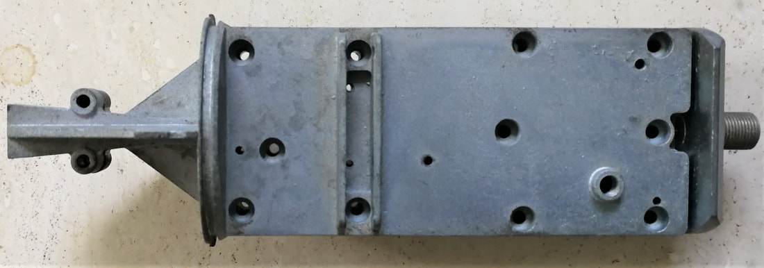
An assembled Philips MC840L MVDS receiver unit (with closing screws removed). The LMDS module looked identical. [Pieter Hooijmans collection]
|
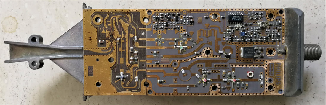
Interior view of the Philips MC840L MVDS 40GHz microwave module. The rigth PCB is generaic for all MVDS/LMDS versions, the left tile is specific per version. [Pieter Hooijmans collection]
|
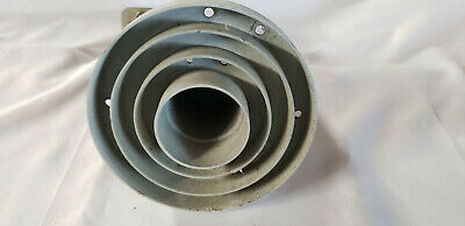
The microwave electronics module was connected to the 42GHz lens and waveguide assembly, shown here from the aperture side. [eBay]
|
The total module plus antenna assembly was finally inserted in a 50cm long black plastic outer housing, which was then fixed onto a mounting bracket for optical alignment. [eBay]
|
Despite the plans for operating MVDS and LMDS systems in multiple countries, only one system was actually deployed: by Swisscom in Switzerland in 1997. Philips Krefeld produced 2000 modules that year, and probably another 8000 maximally the year after. I have no reports on how successful the trial was, nor the field performance. But further deployment was stopped due to the lack of return channel, which made the system only usable for (analogue) TV distribution. Interestingly it is only today, 2019, that systems operating at the same microwave frequencies are being deployed in the exactly similar configuration: microwave distribution of broadband signals to a limited area, typically a neighbourhood of tens of houses. Albeit in the US, using bi-directional 5G systems. In retrospect we can conclude these systems were at least 10 years ahead of their time, but it remains a remarkable piece of craftsmanship that the BU Tuners and especially its microwave team were able to bring such a complex 40GHz module without much problems into volume production.
Overview of the Philips MC800 MVDS and LMDS receiver modules.
BiCMOS technology: QuBIC and HS5, 1996
|
It has already been mentioned several times: all Philips Semiconductor RF ICs discussed so far were still using the same Caen SUBILO technology that was developed in the wake of the Research Weinerth-tuner project in 1976. It had an fT of 6GHz, which made it useable for applications up to 1,5GHz like TV and satellite tuners. Also, it was a pure bipolar technology and lacked CMOS-like options for digital functions. But most importantly the low fT left little margin for high performance and more highly integrated RF functions like the MOPLL. At this time, early 1990s, the only alternative available for higher frequency RF design (say above 2,5GHz) was Gallium Arsenide (GaAs). But GaAs was (and still is) substantially more expensive than silicon, while the integration capabilities are limited. Moving to GaAs was therefore deemed a no-go by most silicon-based RF-IC businesses, but then they needed a different solution.
|
At the time the youngest Philips Semiconductors fab, Albuquerque, New Mexico, where Qubic was developed. [Philips Semiconductors Quality Manual 1996]
|
Picture of the 4" (10cm) HS4 multi project wafer from 1990, containing the Research RF test chips. [Pieter Hooijmans collection]
|
Although so far all RF-ICs used by the BU Tuners were produced in Caen, there was a second Philips fab that made RF products: Albuquerque in New Mexico, USA. They (probably) had some SUBILO compatible technologies in production called High Speed (HS1 to HS3). In 1989 a joint program was started with the Philips Research NatLab (both the technology and the design sectors) to develop a new generation silicon-based RF technology that would support the emerging mobile phone, wireless and high speed optical communication applications, and thus avoiding the move to GaAs. HS4, as the new technology was called, was a 1um three metal layer 4" bipolar technology with an fT of 10-12GHz, and a set of good passive components (resistors and capacitors with low parasitics). In 1990 multi-project wafers were run, confirming the good performance. However, HS4 was never formally taken into production, but was married with the latest C200 1um channel length CMOS to become the first version of a long line or RF technologies: QuBIC1 (for Quality Bipolar CMOS). It was developed in Albuquerque, but subsequently also introduced in the 6" Caen Fab2. When introduced in 1993 it was immediately used for designing the new GSM, DECT and WiFi transceiver ICs which gave Philips a leading position in these emerging domains.
|
|
The Caen Tuner IC group, in contrast, was clearly struggling with the QUBIC challenge. Although the RF performance improvements were obvious, they were worried about the cost increase compared to SUBILO. In practise this meant no decision to move, and developments of the first MOPLL TDA6400 family continued in that technology. Only when by 1996 it became clear that the TDA6402 switched 2-band IC did not meet requirements due to the SUBILO process limitations, the business had no other choice than to move. However, by that time QUBIC1 had been succeeded by QUBIC2, which was essentially a shrink to 0,8um emitter width and C150 (0,75um gate length) and the addition of one metal layer. This made QUBIC2 a 23-mask technology and even more expensive than SUBILO. Although QUBIC2 was heavily used now by the mobile phone IC business, the BL-RF decided they would drop the CMOS part of the technology and work with a bipolar-only drop out of QUBIC2, which was baptized HS5. HS5 became the new workhorse of the Tuner IC group, the first ICs taken in development being the TUN2000 MOPLL, a satellite PLL TSA5059 and the satellite MOPLL TDA8060.
|
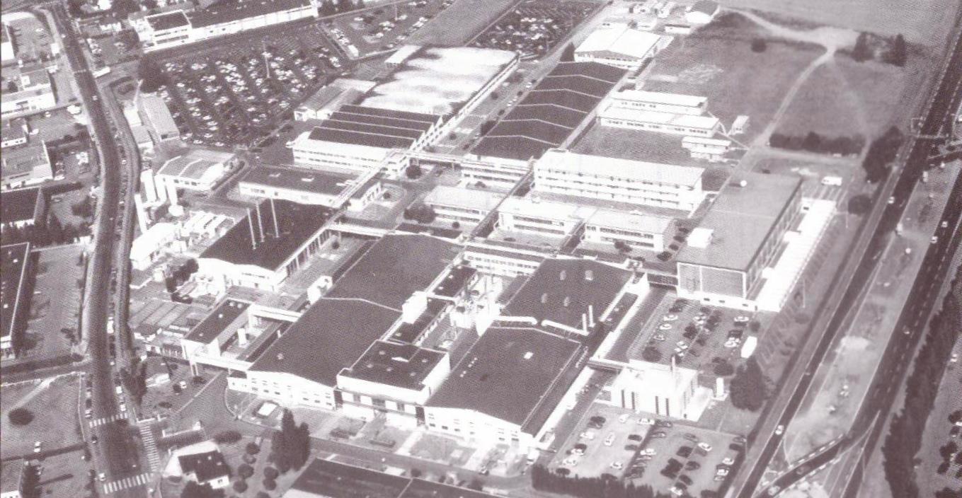
The Philips Semiconductors Caen IC-Fab in 2005. In front below the two identical fab buidlings, IC development was mainly in the building on the right. [Philips Semiconductors Quality Manual 2005]
|
Structural cross section of a Philips Semiconductors QUBIC3 RF bipolar transistor. The etch stop allowed a very narrow (=low capacitance) emitter, the spacers base contact close to the emitter (=low base series resistance). [NXP in the making, 2010]
|
Because of the success of especially the GSM transceiver ICs, development of improved QUBIC versions continued at a high pace, and by 1998 QUBIC3 was released. Using double-poly transistor structures the base resistance could be substantially lower, spacers reduced the emitter width to 0,5um thus allowing the base contact to come very close to the emitter. These measures pushed the fT to the at that time unheard of value of 32GHz; microwave design now came within the reach of the BiCMOS technology! Furthermore, the CMOS now used the C100 baseline, with 0,50um gate length, allowing fair amounts of digital control integrated on the RF chip. QUBIC3 became a widely used technology, allowing much higher levels of functional integration and advanced receiver concepts, including tuner ICs starting with the silicon tuner project.
|
Overview of the first generations QUBIC BiCMOS technology, including HS4 (which was never formally released) and the bipolar-only HS5 derivative.
|

Inside the Philips Semiconductors Caen fab. This was an old-style fab, with separate rooms per process step.
|
DVB-C Digital Cable TV, 1994
|
Because D2MAC was not just planned for the satellite down-link, but also for cable (re)-distribution, it obviously also required a replacement standard for the cable segment, DVB-S serving the satellite broadcast. This became DVB-C, which was designed for a high commonality with DVB-S as far as the digital MPEG and outer error correction coding was concerned. Which meant that the RS(204,188,8) Reed-Solomon coding and subsequent interleaving were common for both standards. But whereas satellite channels suffer mostly from low SNR and thus require as much error-correction coding as possible (in the case of DVB-S the Viterbi convolutional coding), cable transmission has no problems with SNR. Distances are short and if necessary amplifiers are inserted into the network. However, cable reception suffers from reflections in the cable network, resulting in non-flat frequency transmission characteristics and the need for equalization at the receiver side. Secondly there was the need to keep DVB-C compatible with analogue TV, which meant that a digital cable signal had to fit in the 6 (NTSC), 7 (PAL VHF) of 8MHz (PAL UHF) RF TV channels. These combined requirements led to the use of a higher-order modulation scheme: Quadrature Amplitude Modulation (QAM). Although the standard allowed scalability in the modulation order (4, 8, 16, 64 or 256) first generation systems almost exclusively used 64-QAM. At a theoretical minimal SNR of 21dB in combination with a 20% filter roll-off, 64-QAM in an 8MHz band allows a symbol rate of 6,8MS/s or 41Mbit/s raw data rate and 38,5Mbit/s net data rate, of the same order as the QPSK satellite channel. In the US QAM was deployed by the Advanced Television Standards Committee (ATSC) as part of the integral digital cable and terrestrial roll-out. Within the 6MHz NTSC channel bandwidth 64-QAM provided a net data rate of 26,79Mb/s. In a later upgrade the ATSC modulation was increased to 256-QAM, providing the same net data rate of 38,8Mb/s as 64-QAM DVB-C.
|
A QAM64 constellation diagram as used in DVB-C. To code 2^6 = 64 constellation points 6 bits are required. Note that the first three bits code along the Q-axis, the last three bits along the I-axis. [TDA8046H multi-mode QAM demodulator, Philips Semiconductors Application Note AN96048, 1996]
|
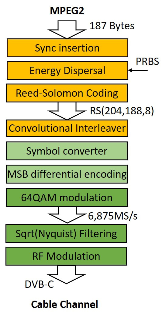
The upstream encoding and modulation sequence for DVB-C 64-QAM.
|
As said, the first four operations in the DVB-C 64-QAM encoding chain are exactly identical to those of DVB-S, thus allowing IRDs with high commonality for both standards. Because no Viterbi convolutional coding is required, after the bit-interleaver the serial bitstream is converted into 6-bit symbols, followed by differential encoding of the two Most Significant Bits (MSB) which makes the constellation diagram rotation indifferent. Finally the three MSBs are used to code the x-component of the QAM constellation (so 8 levels) while the three Least Significant Bits (LSB) encode the y-component (also 8 levels). As in DVB-S, square-root Raised Cosine (RACOS) Nyquist filtering is applied before RF modulation, thus limiting the signal bandwidth to within the 8MHz channel.
On the receive side the first RF-to-IF down-conversion step is completely identical to normal analogue TV reception, with the carrier IF of the symmetrical QAM spectrum in the centre of the 8Hz IF band at 36,15MHz. A synchronous demodulation then removes the carrier and transferres the signal to baseband, as input to the 8- or 9-bit A-to-D converter. In the digital domain clock and carrier recovery takes place, which stabilizes the constellation and thus the eye diagram for demodulation. The receive side square-root RACOS filter optimizes the SNR and is followed by an equalizer. |
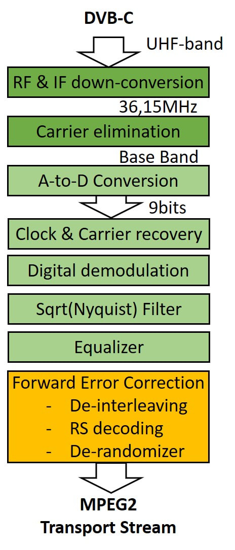
The downstream receiver signal processing sequence for DVB-C 64-QAM.
|
|
As explained, cable networks, with their many branching points, unequal cable section lengths, improper impedance terminations at customers and the generic lossy behaviour of cables result in reflections and thus imperfect frequency-dependent transmission characteristics. In the time domain this is equivalent to echoes, which obviously distort the wanted signal. Without corrections these would result in Inter-Symbol Interference (ISI) which in turn leads to closing of the eye diagram and ultimately decision errors. An adaptive equalizer was thus required to flatten the overall frequency characteristic to allow proper detection. In the Philips Semiconductors TDA8046, one of the first 64QAM demodulator ICs, the equalization was done by the combined function of a Feed Forward Equalizer (FFE) and Decision Feedback Equalizer (DFE). Effectively they could correct echoes from 5 symbols before to 8 symbols behind the target symbol.
DVB-C saw an almost parallel roll-out to the satellite DVB-S because it essentially provided the same advantage to operators: more TV channels per RF channel. The advantage was that the available 38,5Mbit/s could be almost freely allocated by the network operator depending upon the required signal quality. Typically 6 good quality standard definition TV channels could be packed in the 38,5Mb/s container, changing to 3 for HDTV channels or 12 for low quality channels. With DVB-C the number of TV channels distributed by a cable network exploded from the typical 30 analogue to 200 for (still) analogue and digital networks. Often the channels received from multiple DVB-S satellites was remodulated to DVB-C for further cable distribution, making the DVB-S/C combination a very successful new set of standards.
|
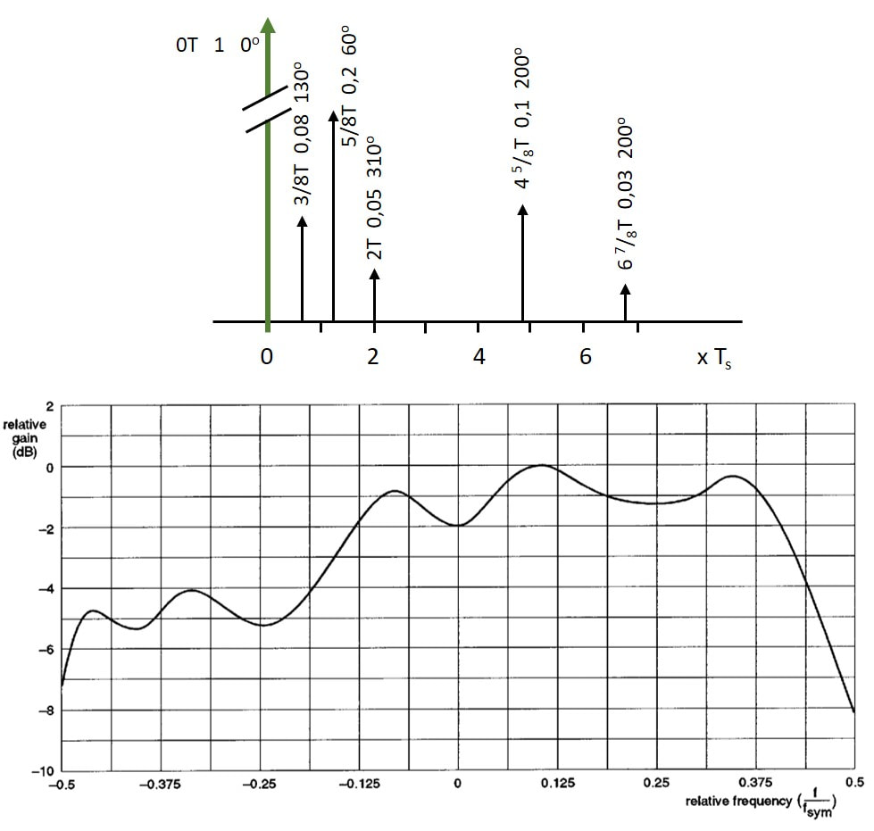
Example of the effect of reflections (or echoes) on the frequency spectrum. At the top the timing diagram, showing the wanted signal amplitude (1) and phase (0 degrees) at time t=0 (green vector), followed by a number of reflections with each a delay (expressed in symbol times T), amplitude and phase. The combined effect of these reflections is a non-flat frequency response as shown in the picture below. The adaptive equalizer in the channel decoder essentially calculated the inverse echo profile to compensate for the different echoes and obtain a flat frequency characteristic. [Philips Semiconductors TDA8045 Data sheet, Feb 1996]
|
Because of the high synergy between DVB-S and DVB-C it is obvious that within Philips both were handled by the same business, Digital Video Systems (DVS) with its development in Eindhoven and Suresnes. Although satellite ran ahead of cable due to aggressive Astra deployment, for each of the generations both a satellite and cable version of the platform was released. In practice the cable volumes were the first years roughly half of the satellite volumes, again almost all as ODM boxes for network operators or (paid) cable service providers.
TD900, the first digital cable tuners, 1995
It has been mentioned already a few times: there were many synergies between the digital satellite and cable developments, and it is therefore no surprise that both segments struggled with similar problems. These were mostly related to:
- uncertainties about the translation of the standard requirements to RF and IF tuner specifications;
- uncertainties about optimal system partitioning, and thus about the functional content of the modules the BU Tuners could potentially develop and supply;
- strong dependence upon the availability of ICs, especially those for the channel decoding;
- unclarity on who would become the leading players and who would drive the de facto interface and system specifications.
|
The first digital cable front end was the TD916-Mk1, which had the following main characteristics:
|
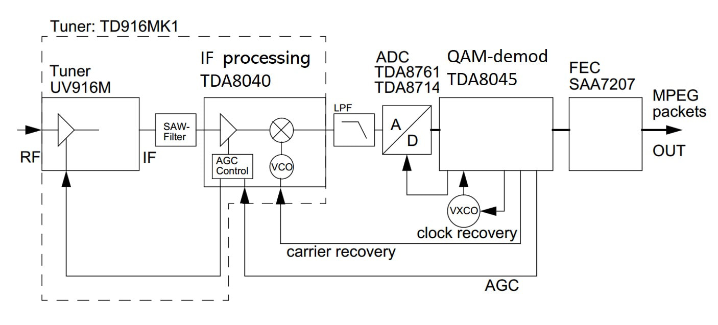
Block diagram of the QA900 full channel decoder board for64-QAM DVB-C. Within the dotted lines the TD916-Mk1 functionality.
|
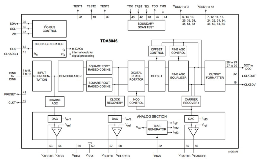
Block diagram of the Philips Semiconductors TDA8046 QAM demodulator/controller. It is identical to the block diagram of the TDA8045, but also covers 256-QAM. All key functions in the DVB-C signal chain are clearly visible. [TDA8046 Data Sheet, 1996]
|
The first application of the TD916 was - just like for the QPSK digital satellite frontends - the Philips Digital Networks G+2 IRD, which required a full channel decoder board. This became the QA900, containing the TD916 front end, the Philips Semiconductors TDA8045 64-QAM demodulator and controller, and the SAA7207 DVB Forward Error Correction IC. The QA900 was very expensive, some 190Hfl per board, and only a few hundred were produced. They were, however, an important learning vehicle and an entry into the digital cable market as early player for both the BU Tuners and Digital Networks.
As a next step the TDA8045. which only handled 8-, 16-, 32- and 64-QAM was upgraded to the TDA8046, which also covered 256-QAM. This also brought US cable applications within reach, as least from the demodulator perspective. As explained in the separate section, on the tuner architecture the US remained a de facto closed market for non-US suppliers due to the use of dual conversion tuners. |
|
A second IC innovation was the TDA9819, a derivative of the TDA9815 multi-standard TV demodulator IC used in the FQ900-Mk2 TV front ends. The main modification was that the synchronous VIF demodulator was now used as 2nd IF demodulator, not converting the signal to zero IF but at a 2nd IF carrier equalt to the symbol rate. This was frequency controlled through an external control loop in the TDA8046 channel decoder. Similarly the AGC was driven from the channel decoder too. The standard VIF and SIF demodulation was otherwise left untouched, such that the TDA9819 could be used for both analogue and digital demodulation/conversion. In practice, however, this never happened within the same module, and the IC was thus relatively expensive because the sound section was never used. Later a dedicated digital-only version was released, the TDA9829.
The TD916 upgraded with the TDA9819 became the TD916-Mk1b, which was the version sampled to potential customers that were building prototype digital cable receivers. With the flat tilt of the UV916M and good phase noise it delivered benchmark performance for this new application. In the meantime the biggest customer remained Philips DVS, which used some 20.000 pieces in their G+3 and G+4 IRD generations. |
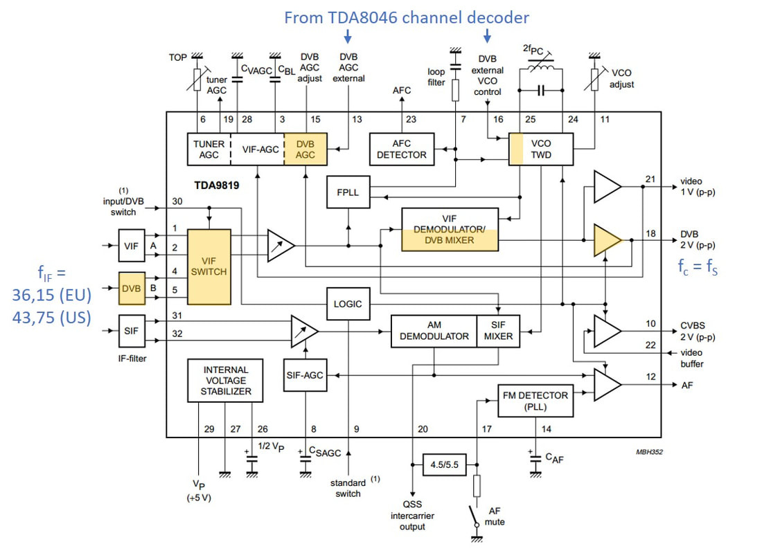
Block diagram of the Philips Semiconductors TDA9819 combo analogue-digital IF IC. The yellow boxes have been added or modified to support the DVB-C down- conversion and control. [TDA9819 Data Sheet, 1996]
|
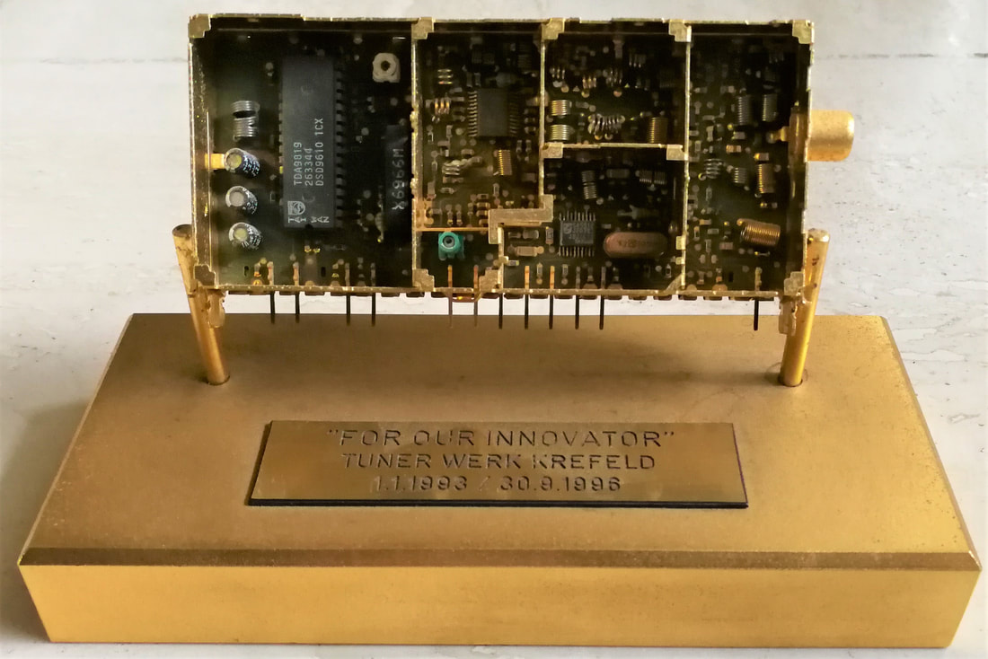
Pictures of the TD916 were impossible to find, and in the end the only sample I have is a golden one, part of the farewell present I got from the team when leaving Krefeld Development for Singapore. [Pieter Hooijmans private collection]
|
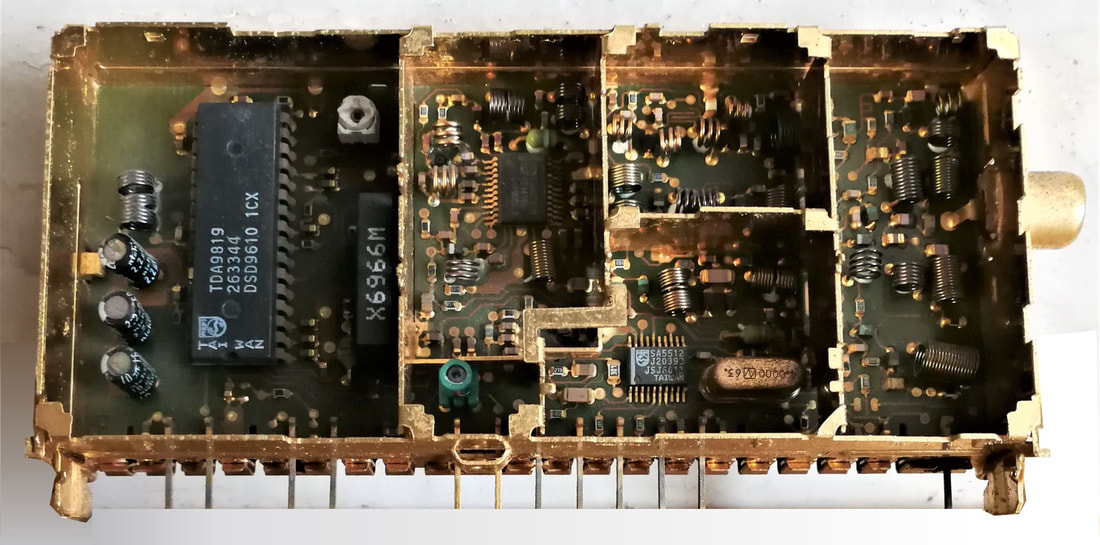
Close up view of the TD916-Mk1b, with in the IF section the large SDIP32 TDA9819. The right part of the module is the UV916M low tilt tuner. [Pieter Hooijmans collection]
|
Although the TD916-Mk1b was giving good performance for the emerging digital cable application, it was obvious that a next generation was needed. Where a number of arguments applied:
- the long 900-frame was no longer state-of-the-art in size, a smaller solution was needed;
- the TDA9819 was much too big and expensive. Furthermore customers wanted more flexibility in their systems, meaning that the SAW filter and down-converter inside the tuner can was no longer considered the optimal partitioning;
- the cable systems were rapidly becoming more complex, including return channels, the need for connecting both digital and analogue tuners, and even Out-of-Band (OOB) tuners for the system control data. In practice this meant the need for RF loop-through functions;
- there was a lot of internal discussion whether a next generation should be World Standard Pinning or not.
CD1500, a new framing concept, 1998
|
The 1500 mechanics were revolutionary in two ways. To start, it was - as far as I know - the first product in the world that used the WSP pining mechanical specification for a product not a standard terrestrial tuner like the UV1300. Remember that the WSP was not a formally managed standard, only a recommendation for tuner mechanical interfacing. Right after the defintion of the tuner WSP interface all discussions on other functions (front ends, splitter-tuners et cetera) and/or different frame sizes were broken off between Philips, Alps and Matsushita. The CD1500 was the first to introduced a "WSP-like" module of different size than the UV1300. It was driven by the then internal BU Tuners desire to converge to one single pinning, which should be the WSP. (As already hinted at, this convergence to a single pinning standard would never happen due to the multi media FI/FR/FM1200 Philips pinning success).
The 1500 introduced a second novelty: a completely new frame concept. One of the issues the BU was increasingly struggeling with was the diversity and associated cost of frames. As has been shown in the preceding chapters, there was a strong policy, especially after the introduction of the one piece folded frames in the 700 and 900 families, to limit the number of frame versions. Every frame modification or model cost an expensive tool set at the frame manufacturer. In practice this meant that all 900 familie products were expected to use either the TP900, UV900, FI900 or FQ900 frame versions. In these frames the tuner was at a fixed position with additionally some space in front (TP) or behind the tuner (FI/FQ). However, especially with the introduction of digital tuners this became a problem. Many products required additional functionality: a loopthrough or modulator in front of the tuner, second down-conversion or IF filtering behind the tuner. A solution was to separate (again) the outer frame and the inner grounding frame. The latter became a kind of "spider" insert that could in principle be of any shape and positioned at any location inside the outer frame. This created a lot of flexibility, where, if an insert could not be re-used, only a new insert tool was required. Finally the top cover became of a slide-on design. Two embossements on the sliding cover and the insert provided ground contact. |
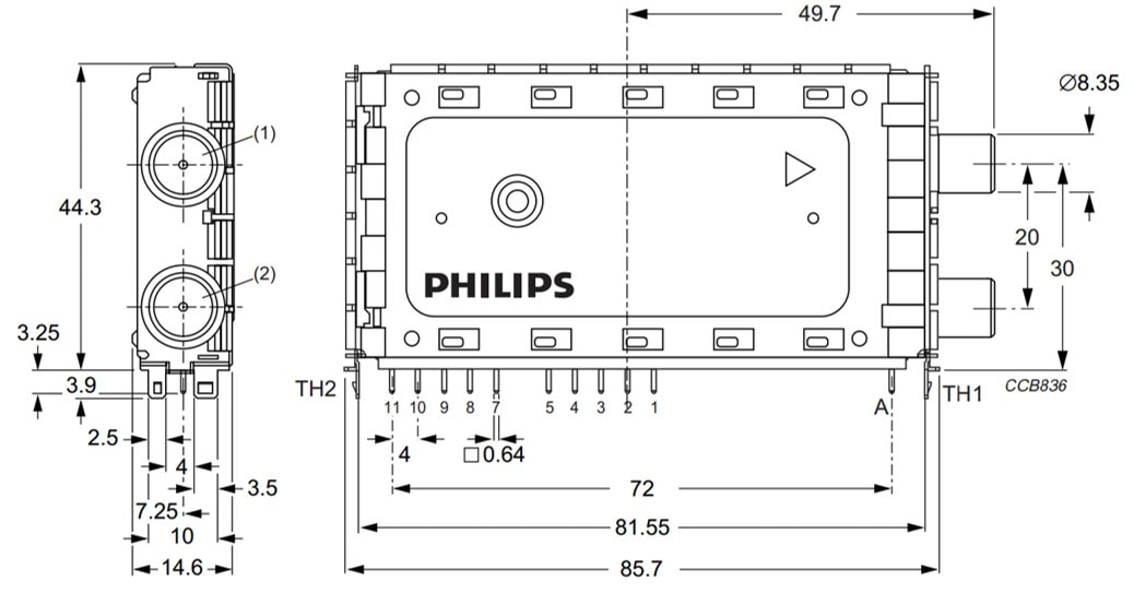
The new mechanical design of the CD1500(L), with WSP compatible pinning, flexible inserts and a sliding top cover. [BU Tuners CD1500(L) Data Sheet, March 2000]
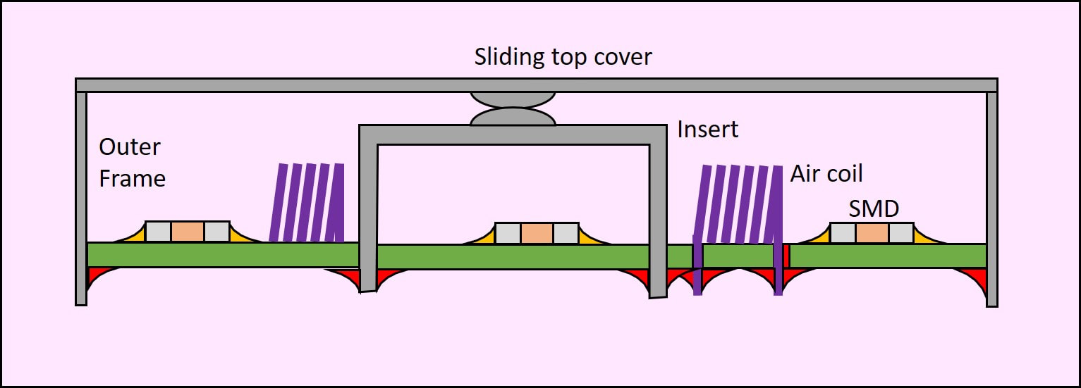
Conceptual drawing of the 1500 grounding insert and its contact to the top cover. For soldering the mixed technology is used, with first reflow SMD soldering on the top A-side, then wired components and insert placement and B-side wave soldering.
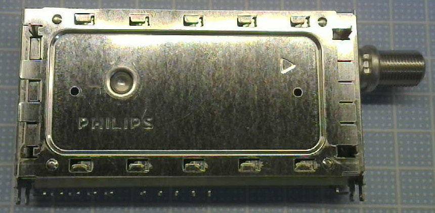
A-side top cover of the CD1536/FH The sliding connection hooks of the cover are clearly visible, as is the circular embossement for the insert contact.
|
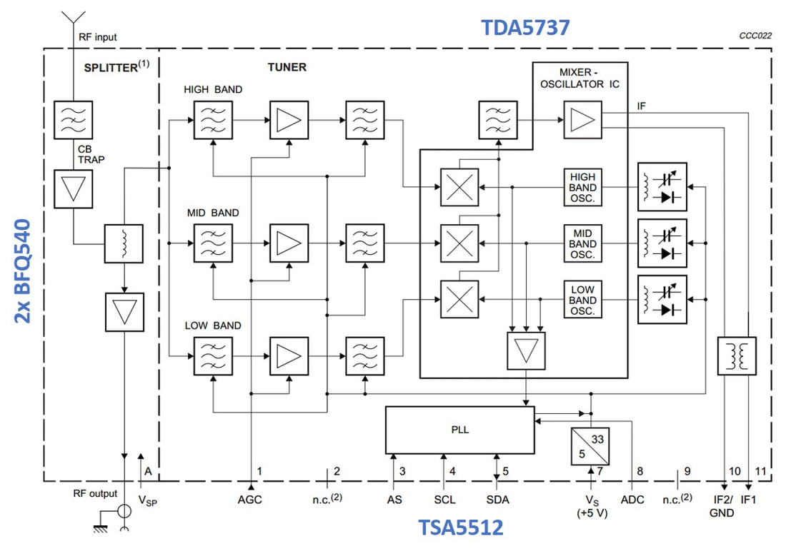
Block diagram of the CD1500(L) digital cable tuner with loop-through splitter.
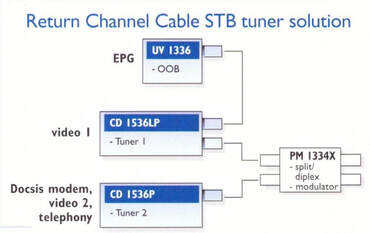
US Cable Modem application using two CD1536, of which one with loop-through (CD1536L). The Electronic Program Guide (EPG) required lower quality reception and used a cheaper UV1336 standard tuner. The PM1334X was a broadband active splitter with UHF modulator (M) and loop-through (X). [Philips BU Tuners CD1500 Product Leaflet, 2000]
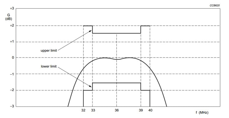
For reducing the equalizer requirements of cable tuners, low tilt remained an important specification. This is the +/-1dB tilt spec of the CD1500. [CD1500 Data Sheet]
|
Electrically the CD1500 was quite different from the TD916-Mk1b, based on the early market feedback obtained with that first product:
|
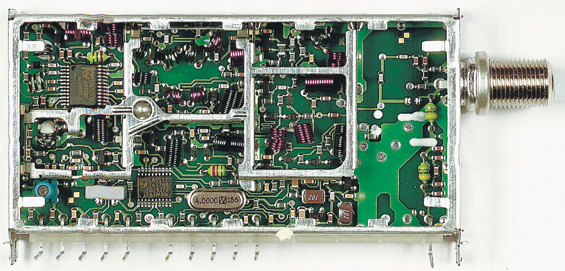
Top view of the US-version CD1536/FH. Note the revolutionary insert with its cover contact. On the right is space for a diplexer (not present in this version), at the bottom around the TSA5512 PLL is the discrete DC/DC-converter with some large capacitors. [Darko Jancin]
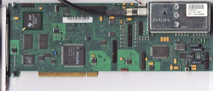
A rare and huge PCI card of Fujitsu-Siemens, containing the CD1516/IH.
|
The CD1500 was not a huge success for several reasons. To start, volumes remained relatively low (proably less than 50.000 per year) because the US market was effectively closed for non dual conversion tuners. This left the European cable market, which was much smaller than e.g. the satellite market and limited to The Netherlands and Belgium and some large urban areas. Also, cable modems were not standard consumer devices, but distributed by the cable operators "for free" as part of the subscription. There was therefore not much need for differentiation, and lowest cost was the main driver. Finally, the 1500 concept, although very robust from an electrical perspective, turned out to be too big and therefore relatively too expensive. But what killed the insert concept of the 1500 were problems with cover-to-insert contacts stability, leading to crackle and immunity problems. The 1500 never became a big family of products, being limited to the CD1500, the DVB-T TD1544 and the second generation CD(M)1500.
|
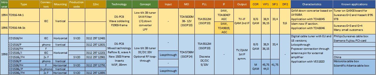
Overview of the first two generations Philips digital cable tuners, TD900 and CD1500.
TUN2000 and other MOPLLs, 1999
As explained earlier, the ultimate ambition of the BU Tuners with respect to functional IC integration was the Mixer Oscillator PLL or MOPLL. The first implementation with the TDA6402/3 was not a huge success because it forced the return to a switched 2-band architecture, not the core concept strategy of the business. Almost in parallel with the TDA6402 design-in in the UV1336, discussions started on the definition of a real 3-band MOPLL that would fit the standard Philips tuner architecture much better. However, there were still limitations, because the largest SSOP package that Philips Semiconductors had available at the time was the SSOP32. Already bigger than the SSOP28 of the TDA6402, but still relatively short on pins. As a result the IC architecture that was defined was still a compromise and looked as follows:
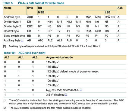
Details on the new Auxiliary Byte (AB) and the AGC Level bits (AL0-AL2). [TDA6500 Data Sheet]
|
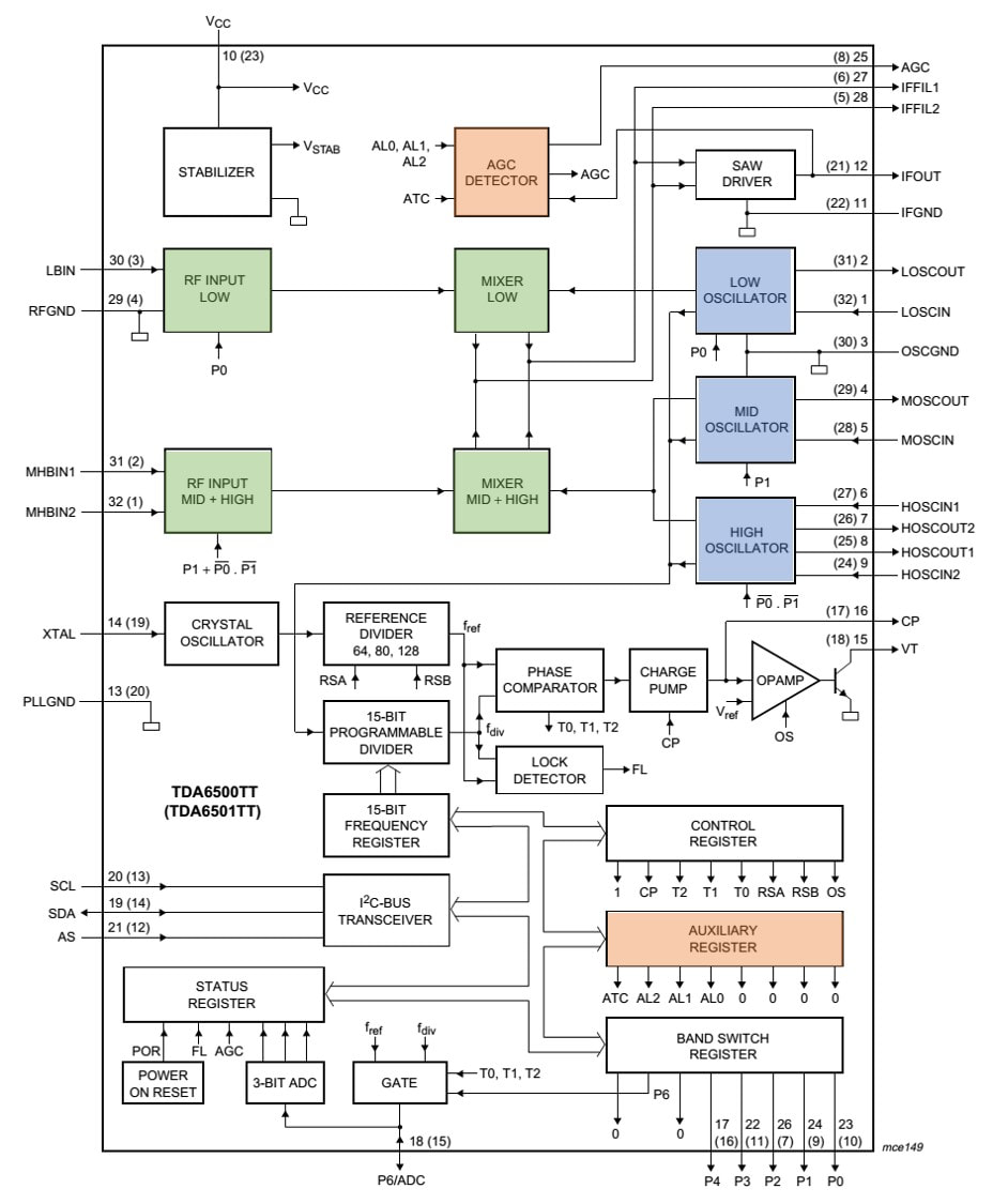
The Philips TUN2000 3B-MOPLL, custom designed for the BU Tuners. It was later released as open market type TDA6500. [Philips Semiconductors TUN2000 Data Sheet, March 1999, via Huub Maas and Oswald Moonen, TDA6500/01 Data Sheet, June 2005]
With the new MOPLL came other changes. One of the things that had mightily frustrated the BU Tuners for many years was that ICs developed by Philips Semiconductors with and for the BU were almost immediately available for competition too. This always fed the feeling that "the BU knowlwedge was leaked to competition". At the same time Semiconductors developed proprietary ICs for competitors, especially Alps, that were marked e.g. ALP04. Because they were proprietary to that customer Semiconductors was of course not allowed to tell anything to the BU Tuners. Although the positions of both Tuners and Semiconductors were perfectly justified, they were the result of an undeniable trend: the shift of "architecture ownership" from the module to the semiconductor key components as a result of the continuous integration trend.
|
It was therefore decided that the BU would do the same as its competition! Especially the addition of the W-AGC was deemed extremely important for keeping as long as possible confidential, and the new MOPLL thus obtained a unique BU Tuners code: TUN2000. (With some pride I can say I came up with the name). The IC was defined in 1997 and was released in 1999. At the same time the BU now played the second sourcing game all out, just like BGTV was doing with them. Siemens was thus asked to develop a 1:1 copy of the TUN2000, to force Semiconductors to come with a sufficiently aggressive price for the TUN2000. The Siemens IC was baptised TUN2010, and released roughly a year after the TUN2000. However, it was not a 1:1 copy. On the one hand the Siemens engineers wanted more safety margins in their oscillators, requiring a 4-pin Mid Band oscillator too. Secondly they had a TSSOP38 package, allowing a few more grounding pins as well as a 4-pin IF filter, allowing higher order IF filters. The two ICs were thus very similar but not drop-in replacements, still requiring different lay-outs. However, to convince Siemens Semiconductors - which was spun out of Siemens as Infineon in early 1999 - to develop the IC at its own expenses (because the BU was incapable of paying them) the BU Tuners had to commit a minimal volume of 4Mio ICs per year, which amounted to 25% of the combined tuner and multimedia frontend volumes.
Unique picture of the TUN2000 layout with the 32 bonding connections indicated. Or more precisely, the TUN2001 mirrored lay-out. [via Darko Jancin]
The TSSOP32 package as used for the TUN2000 and TDA6500 family of MOPLLs. The size of the package was 6x11mm, pin pitch 0,65mm. [Philips Semiconductors]
|
Not long after the TUN2000 Philips Semiconductors released the TDA6500 and its mirrored version TDA6501, which were - possibly with the exception of some pinning details - identical to the TUN2000. Although with TI and Infineon there was now increased competition in MOPLLs, Philips remained the market leader and the TDA6500 was a very successful family, running in high numbers. Then something strange happened: the BU started using versions of the TDA6500 without Wideband AGC. Initially this was again a product with a proprieatary product coding (Winner1), later the TDA6508 was used (in the UV1300-Mk4) and TDA6509 (FM1200-Mk5). Why exactly the BU, after having worked for many years on internal W-AGC, went away from it is still unclear. At this moment I can't imagine other reasons than cost.
In the meantime the BU was struggeling to accumulate the required 25% of its MOPLL load or 4Mio pieces for Infineon's TUN2010. Not meeting that target meant a price penalty. The TUN2010 was therefore used in the FI/FM1200-Mk3 too. However, when that moved towards digital standards a problem arose because the TUN2010 didn't have good enough phase noise for DVB-C and DVB-T. Infineon therefore launched the (open market) TUA6034, specifically for those applications. The combined use of TUN2010 and TUA6034 provided the promised volumes, although no new Philips-Infineon co-design was ever started again. |
And so, roughly ten years after it had been defined as the ultimate integration target for tuner ICs around 1990, the MOPLL was there and established itself as the new standard for almost all tuners. MO and PLLs were only left for specific products with e.g. extreme phase noise requirements. The original BU vision that MOPLL was the way to structural cost reduction als turned to reality. Although the forecasted MOPLL price of Semiconductors had been 1,2USD when the discussions started at the beginning of the decade, by the time the TUN2000 was introduced the internal price was 0,54USD, with a target of 0,4USD in the coming two years. But with QUBIC2/HS5 RF integration technology had also finally taken off and reached performance levels allowing high integration. As such this was a fitting milestone at the end of the century.
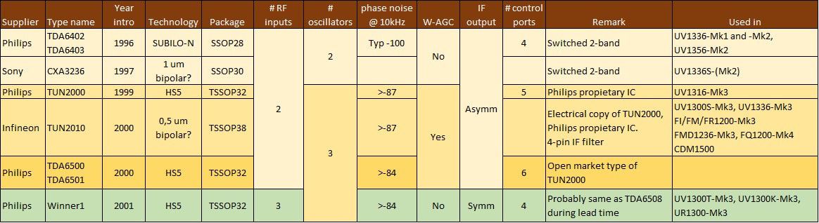
Overview of the first generations MOPLL IC used by Philips BU Tuners, their main characteristics and the products that used them.
UV1300-MK3 with MOPLL and radio, 2000
After all struggles to get the World Standard Pinning, the mixed technology process and the MOPLL introduced, it is more than fitting to dedicate the section that closes this chapter, the decade and even the century to the UV1300-Mk3. As we will see this was also the last real analogue TV tuner family, to be replaced by analogue-digital tuners in the next decade. And it was the last family to successfully offer a broad range of often still unique options.
|
The main differentiation of the UV1300-Mk3 were the many different options for the input functionality:
|
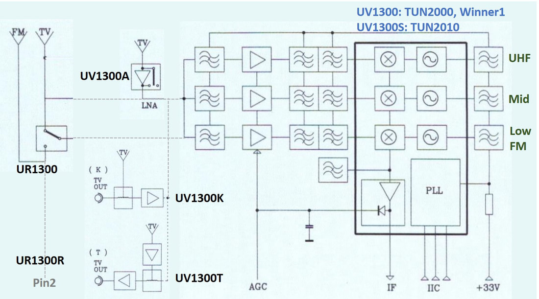
Block diagram of the UV1300-Mk3 tuner family, especially showing the different options for the input functionality. [Philips Tuners UV1300-Mk3 product leaflet, 2000]
|
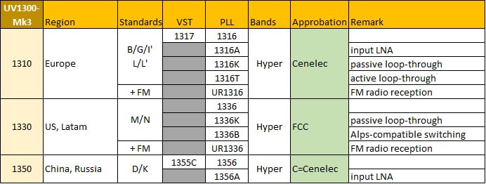
Overview of the Philips UV1300-Mk3 tuner family. This would be the generation with most functional featuring, based on LNA, loop-through and FM-radio options. Note the rapidly diminishing number of VST versions.
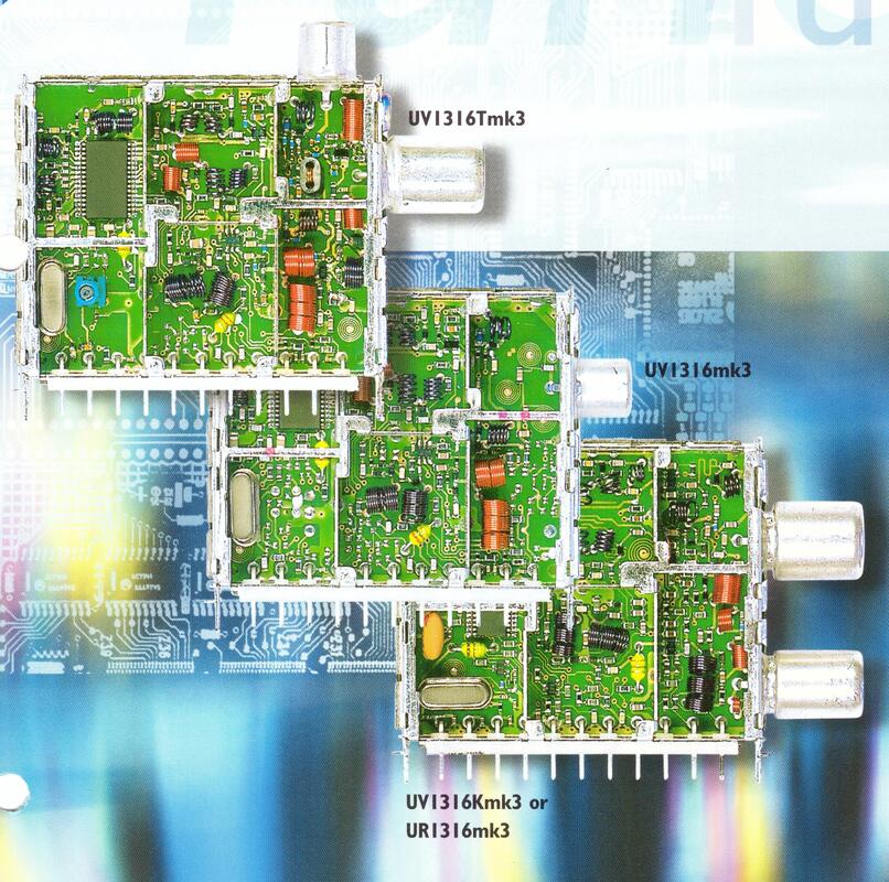
Front picture of the UV1300-Mk3 product leaflet, showing the different connector configurations. [Philips Components, 2000]
|
The basic IC for the UV1300-Mk3 family was as expected the new, proprietary TUN2000 MOPLL of Philips Semiconductors. It was used in the three main types of the family: UV1316 for PAL-B/G/I/L, the UV1356 for PAL-D/K and the UV1336 for NTSC-M/N. For the NTSC tuners the BU had to accept that - in the aftermath of the UV1336-Mk1 disaster - the Alps configuration had become the market standard, and most tuners thus were of the UV1336B model, with Alps-compatible frequency bands and switching. There was only one single VST model left, the UV1317, which continued to use the TDA5737 MO-IC. However, PLL Tuner prices had come down so dramatically with the WSP, that the concept saving of VST made no sense anymore, and it was only used for the most low-end sets. The Mk3 was also the first tuner generation to offer horizontal mounting, which became important with the emergence of much thinner (LCD) flat panel display TVs. Other than that the process did not change and stayed with the reliable mixed technology. The only change on the mechanical side was that the pin block moved from the interior to the exterior of the frame, thus creating more layout space. The Wideband AGC became a standard option, although not offered for free: models with the W-AGC activated were different type numbers (suffix G). As one of the cost reduction steps the Mk3 introduced the BF1204 twin-MOSFET with internal biasing, in a 6-pin SOT343 package. It was used for the Low and Mid bands and is visible on the pictures just below the central horizontal screen.
|
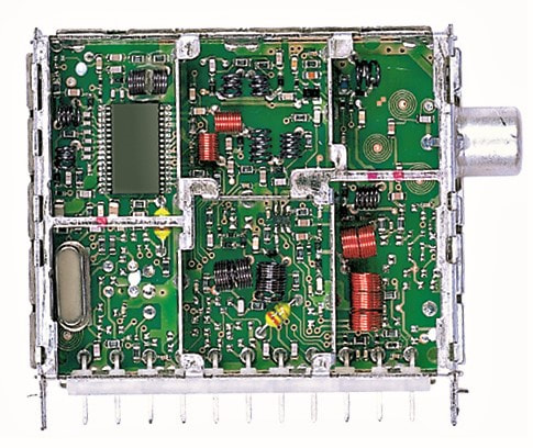
The Philips UV1316/AP-Mk3 with the 32pin TUN2000 MOPLL. Note that the front area of the PCB on the right is essentially empty to accommodate the splitters. [Darko Jancin]
|
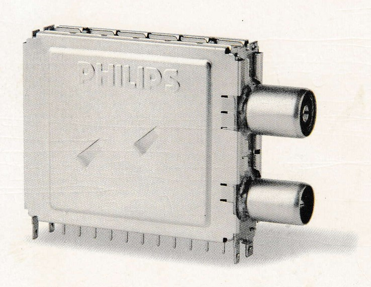
Exterior view of the Philips UV1316K-Mk3 (with passive loop-through splitter) and UR1316-Mk3 (with the lower connector the FM radio input). [Philips Display Components Product Leaflet]
|
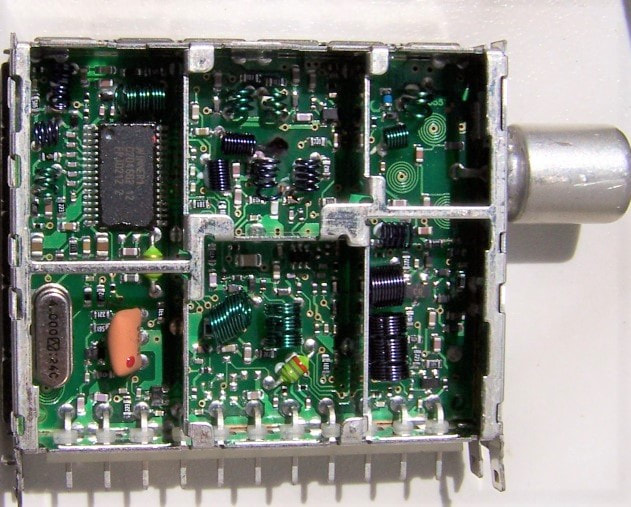
The Philips UR1316R/AI-Mk3 tuner with FM radio reception. This version had the FM input on pin2. Note the orange 10,7MHz IF filter lower left. [Elektroda.pl]
|
Quickly behind the standard tuners the innovative models appeared, like the UR1300 TV plus FM radio tuner. This feature was very successfully launched with the FM1200-Mk2 multimedia front end family two years earlier, and was now copied into the tuner family. Because the TUN2000 had five switching ports one could be used to switch the FM mode. There were two basic versions of the UR1300: with the FM input on a second (male) IEC connector, or with the FM input on pin2. (The NTSC UR1336 always used two F-connectors). The UV1316T splitter-tuner had yet another connector arrangement, with the phono output connector on the top of the tuner. The UR1316, UV1316T and UV1316K (with passive loopthrough) were the versions that used the - still mysterious - Winner MOPLL.
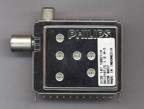
Exterior view of the Philips UV1316T/SIGH-Mk3, symmetrical output, IEC connector, W-AGC, horizontal mounting. This one is produced in Batam, week 37 of 2004.
|
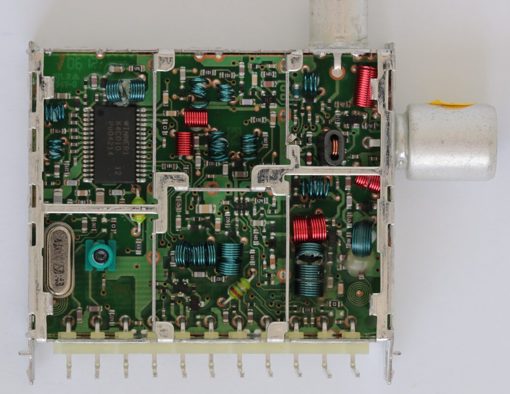
The Philips UV1316/SIGHQ-Mk3. The Q refers to the two-bit decoder, two transistors which are visible in the lower centre. [Henk van der Wijst collection]
|
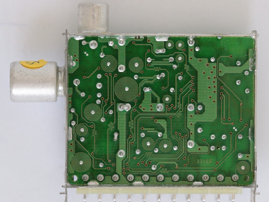
A-side oft he Philips UV1316T/AIGHQ-3. Note the clean arrangement with 13 printed coils. On the centre line the three printed BPF top capacitors are visible. [Henk van der Wijst collection]
|
By this time finally the Infineon TUN2010, the copy of the Philips TUN2000, came available. As already mentioned, Infineon only committed to the development of the TUN2010 if the BU would use at least 4Mio ICs per year. As in almost all of these cases the customer has much more trouble than foreseen in reaching these committed numbers, and the BU Tuners was not different. By the time the TUN2010 arrived the bulk of the Mk3 family was finished and running in volume, all based on the TUN2000. Because the two ICs were not pin compatible (the TUN2010 used a TSSOP38 vs. the TSSOP32 for the TUN2000) every model required a (modest) re-design. In the end the same approach was taken as with the Sony MOPLL in the Mk2 generation: a second version of the UV1316 was designed using the TUN2010, called UV1316S-MK3.
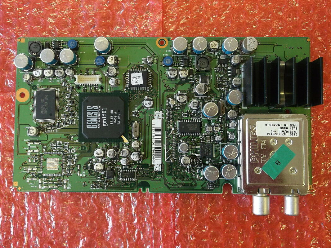
The UR1316 TV-FM tuner was introduced within Philips in the first generations LCD TV chassis. This is the LC4.9 small signal panel from 2004, with left the GM1501 RGB-to-LCD scaler IC.
|
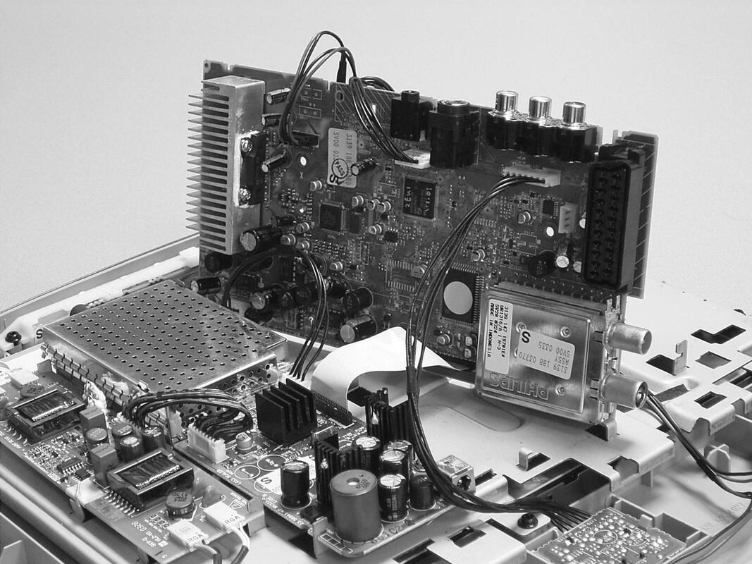
The UR1316 in the second in-house developed LCD-TV chassis, the LC13 from 2003. Note that the UR1316 had the additional imprint TV FM on the cover. [Philips LC13E Service Manual, 2003]
|
|
The UV1300-Mk3 became, in hindsight, the last of the big Philips analogue tuner generations, with a broad family covering all relevant standards and with a nice set of features. It was used in all main Philips TV chassis of the period: the Brugge high/mid end EM chassis, launched in the year 2000, which featured the ultimate analog TV features like Progressive Scan, Pixel Plus, Digital Scan and of course Ambilight. Next were the 2001 L01 and 2004 L04 low end chassis from Singapore. The L01 chassis, also called CTV2001, showed the maximum level of integration for low end analogue TV, being designed around just three main ICs: the Philips Semiconductors TDA95xx Ultimate One Chip (UOC), TDA 9853 analogue sound processor and Micronas MSP34X5 digital sound processor. (Plus of course a microcontroller and some small support ICs). These were, apart from some late models, the last picture tube chassis from Philips. Exactly around the turn of the century the new Liquid Crystal Display (LCD) technology broke through, which will be discussed in much more detail in the next chapter. For the tuner this had initially not much impact, other than the increased need for horizontal mounting versions, but that was now a standard option in the Mk3 family. Although the first LC1 LCD chassis was essentially an ODM purchase and re-label from Korean LG (the former Lucky Goldstar, which was now partially owned by Philips) and used LG tuners. With the LC1.20 for Magnavox the first Mk3 tuner was introduced, the UR1336. In general the FM-radio was a very successful feature, and the UR1316 and UR1336 were widely used in the Philips chassis, both low end and high end. The same is valid for the LNA version UV1356A in China, which was the standard tuner for Asia. At the same time the Philips TV group consistently continued its second sourcing policy. For example in the L04 chassis the split was: all European tuners UV1316 or UR1316, all Asia tuners UV1356A, all NTSC tuners Alps, all European and Asian splitter-tuners Alps. That must have given Alps roughly 35% of the volume.
|
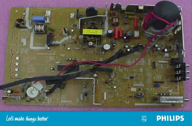
The UV13100-Mk3 tuner lower right in the Philips L01 chassis. The large IC in the centre is the Micronas digital sound processer, the Philips UOC was mounted on the SMD-side. [Philips Service training presentation CTV2001 chassis, 2001]
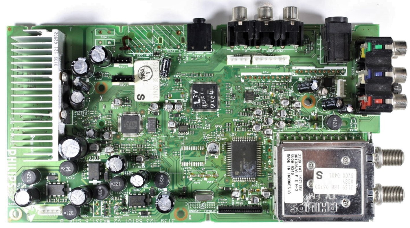
One of the last Mk3 applications: the UR1336/AFSH-Mk3 in the Philips Magnavox 20PF7835 LC4.2 LCD-TV from 2004.
|
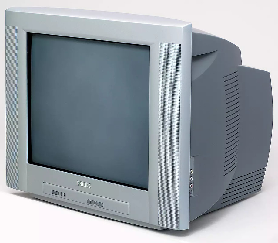
The first of the Philips low end CRT chassis that introduced the UV/UR1300-Mk3: the L01.1E from 2001. This is the 21PT5407.
|
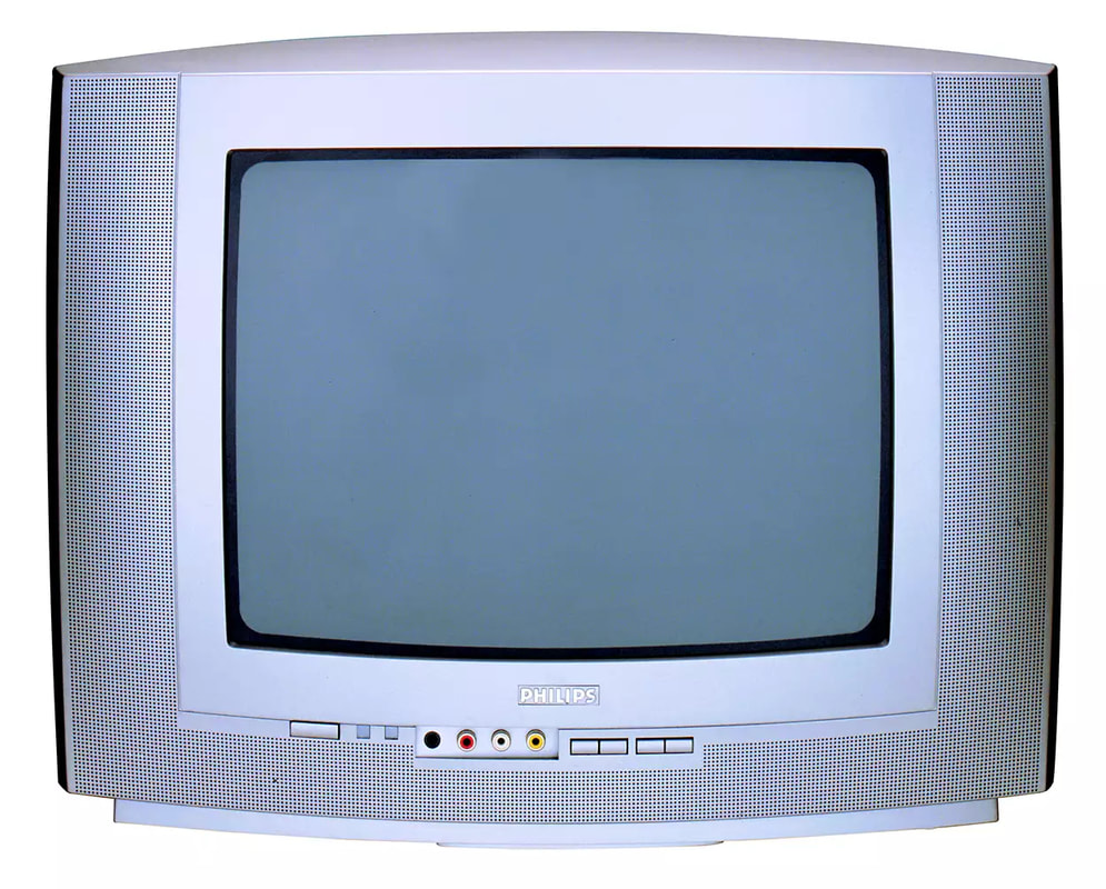
The Philips L03.1L chassis from 2003, essentially a continuation of the L01 for Latam. It would turn out to be the last in-house developed low end CRT chassis. Here the 14PT3131.
|
The LC03, also from 2003, introduced LCD screens in low end TV, obviously mainly 16:9 screens. It was amid end chassis, based on the BOCMA IC. Here the 23PF9945.
|
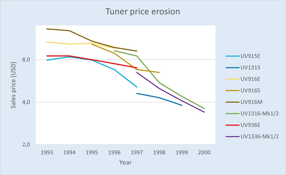
Sales price trend of the main Philips tuner models between 1993 and 2000. For clarity a logarithmic vertical scale is used. Prices are mostly internal Philips transfer prices, which were roughly equal to the average market price. The European 16 tuners showed an average yearly price erosion of 16,6%!
|
The biggest issue, however, was the devastating price erosion of the basic tuner function, as triggered by the World Standard Pinning. At the moment of introduction the sales price of a standard UV1316-Mk3 PAL tuner was just 3,4USD, of the NTSC UV1336 even lower at 3,1USD. Only seven years earlier those prices had been 13,2 and 8,5USD, respectively. Of course the tuner price pressure had been passed on to the component suppliers, with the price of an MO or PLL IC now as low as 0,20USD, while the TUN2000 at introduction was just 0,54USD.
In parallel the volumes started declining. At the peak of the UV1316-Mk2 family total tuner volumes had been 18,5Mio pieces per year, but by 2000, at the introduction of the UV1300-Mk3, this volume had reduced to 16,5Mio and would collapse the next year to 10,7Mio due to the internet bubble crisis. Part of this was the trend to digital tuners, but because of the low prices Philips was in many cases unable to compete for the most low end segments, given the company margin requirements. This in turn meant that tuners didn't generate enough money to justify investments in (key components for) next generations, making the BU much more vulnerable and essentially destined to buy whatever the semiconductor suppliers had available. All in all the UV1300-Mk3 launch was essentially the beginning of the end, which is the reason I called it the last real tuner generation earlier. |
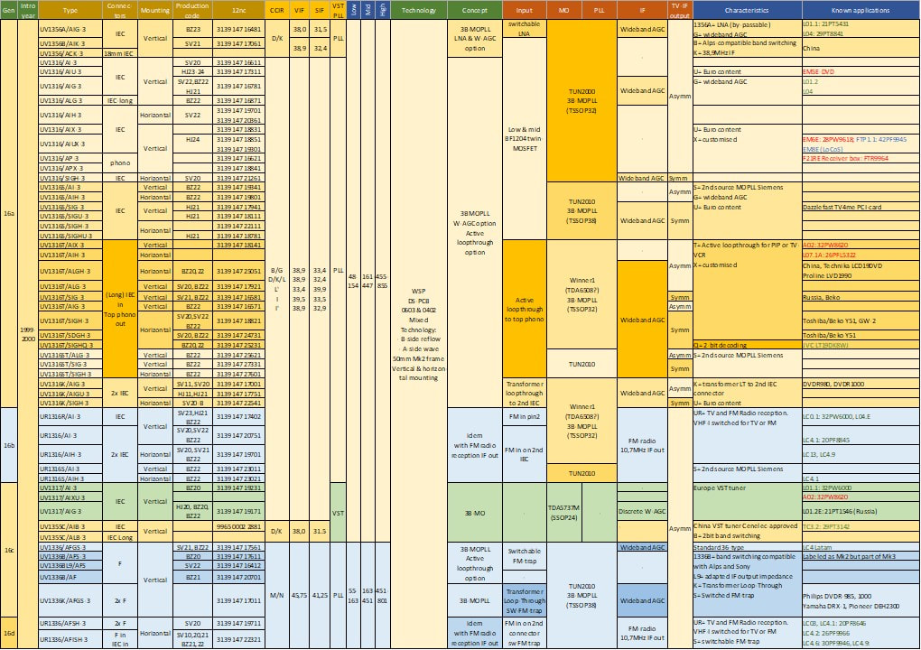
Overview of the Philips UV1300-Mk3 WSP tuner family, including the UR1300-Mk3 with FM-radio reception. Production codes refer to the Singapore/Batam fab (SV), Suzhou (BZ) anf Kwidzyn (HJ). In the last column known applications red refer to Philips CTV chassis, green to Philips LCD chassis and black to other applications.
Summary and Conclusions
The last decade of the 20th century was quite an eventful one for the 50 year old Philips tuner activities, now concentrated in the BU Tuners. To summarize a few of the major developments in this last decade that have been described:
- closing of the Eindhoven activities, the cradle of Philips tuner activities, and concentration in Krefeld and Singapore;
- closing of all Western European production facilities, and the opening - next to Singapore - of Batam, Kwydzin and Suzhou as main volume production sites;
- the intitial rise to the record volume of 21Mio tuners and tuner-modulators in 1998, followed by a sharp decline triggered by the World Standard Pinning to 11Mio two years later;
- similarly sales, which had spectacularly increased from a stable 150MioUSD up to 1993 to 250MioUSD in 1995, started a steady decline, mainly due to a strong price erosion in tuners, to an all-time low of 125MioUSD in 1999. The only good development was the growing contribution of new non-tuner products to the business: from virtually 0% in 1990 to 35% in module count by 2000, and in sales value more than 60%. However, even this could not compensate the price erosion in tuners;
- integration levels had spectacularly increased, from the still predominantly discrete-VST UV900 family to the UV1300-Mk3 with high performance MOPLL ICs. The same was often even more valid for the IF and digital demodulation domains. This facilitated strong size and cost reductions, but the downside was a rapidly dependence on the semiconductor suppliers;
- some very effective tuner (and IF) features were introduced and broadly used by the market: combined TV and FM-radio reception (first in the FR/FM1200-Mk2, than the UR1300-Mk2 and 3), tuners with LNA (mainly for Asia), Wideband AGC and splitter-tuners;
- the initially very successful emergence of a number of new business activities in the domains of satellite reception (both LNB and front end), TV front ends and communication modules. However, just when they emerged many were cut short by the new BU management, leaving only multimedia frontends for PCs as a real volume success. Nevertheless by 2000 the non-tuner products formed 50% of the volume and around 70% of the sales. Unfortunately the growth of new products could not compensate the decline in tuners;
- the emergence of digital broadcast standards for satellite, cable and terrestrial, creating new opportunities but also uncertinties due to the struggeling traditional customers;
- the loss of both Philips TV (BGTV) and Philips VCR (IR3) as captive customers, both of them using increasing numbers of modules from competitors, mostly Alps. The amount of modules lost this way was around 4,5Mio tuners and 1,5Mio tuner-modulators in 1998, amounting to roughly 40MioUSD internal sales and margins for the tuner business, 25% of the business at the time.
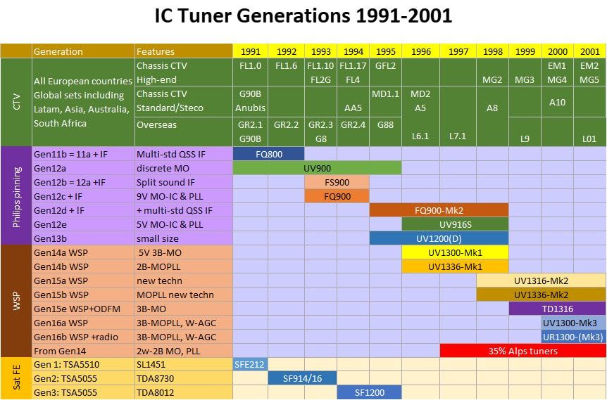
The use of Philips BU Tuners families in the different Philips TV chassis during the 1990s. The red lines indicate the increasing use of external module suppliers in Philips consumer products.
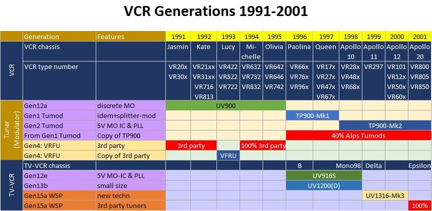
|
Most of these developments, some positive, some negative, can still be described as "part of the game". No market is stable, technology and applications develop continuously, customers come and go. The most devastating development, however, was purely internal and of severe structural impact. For 40 years the Philips Tuner business had been one of the shining technology stars of the company, with especially internally an undisputed position as supplier of choice for any Philips consumer product that require and RF module. However, in the last 7 years of the 1990s this had been turned around, the BU Tuners now being seen by Consumer Electronics (both BGTV and iR3) as a non-strategic module supplier of commodity tuners, and not as a very competent RF player that could and should support the continuous innovations and new applications in this domain. Especially BGTV, struggeling for its own survival, was not willing to allow investments of the scarce financial resources into applications not used in a TV. Which essentially meantanyhting else than a standard low cost tuner. This was made worse by the acceptance of these statements and developments by the BU Mangaer Rob de Ridder, who followed BGTV and blocked investments into new applications.
|
|
But probably the most dramatic development was the changed appreciation for the tuner - or more in general the RF module - business and competency of the BU. Where in the past, that is up to 1990, it had always been considered a key asset of the Philips consumer business and was kept within the core television business, by the year 2000 this perception had changed to the opposite. With its factories and the associated need for investments, its considerable number of (factory) employees and relatively expensive RF R&D it was, in the eyes of the new Philips president Boonstra, a liability. With a BU management, mostly people with no knowledge of technology and RF, that was not able to formulate a clear strategy for its business, the BU was obviously coming into a dangerous squeeze.
This chapter, which describes so many interesting and innovative new products that made the BU Tuners such a great place to work during this decade, therefore ends gloomily. Neither Philips, nor its TV and Tuner business were what they used to be. Big changes lay ahead! |
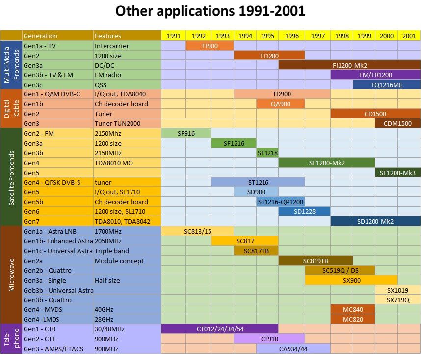
Overview of the Philips BU Tuners new products between 1990 and 2000. These were predominantly sold to external customers.
|
References
Finding information for the many products covered in this chapter has not always been easy, also because some of the important sources fell away. These were the main sources I used:
- In 1990 and 1992 for a last time Philips Components issued its famous Data Books, including those covering tuners:
- Philips Display Components Data Handbook "Television Tuners, Coaxial Aerial Input Assemblies" (DC03), 1990
FE618Q, UV411, UV411HKM, UV417/18, UV431, UV461/62, UV471/72, UV615S, UV617/18, UV711/12, UV711/12NZ, UV751/52, UV815/16, UV915/16E, UV933/34, UV935/36, UV963/64, UV983/84, SFE212 - Philips Display Components Data Handbook "Television Tuners, Coaxial Aerial Input Assemblies" (DC03), 1992
UV617/18, UV816, UV913/14, UV915E/16E, UV916H, UV933/34, UV935/36E, U943C/44C, UV953/54, UV963/64, UV973/74, UV983/84, FE618Q, FQ816, FQ816ME, FQ816MF, FQ844, FI916, FS916, FS936, FS986, SFE212S, SF914/16, SC813, SC815
- Philips Display Components Data Handbook "Television Tuners, Coaxial Aerial Input Assemblies" (DC03), 1990
- After the stopping of the big databooks Philips Components and the BU Tuners issued individual data sheets of tuners. However, these are not systemetically published or archived, so my collection is far from complete:
- UV1315, UV1316, UV1316-Mk2
- FI1216-Mk2, FI1216MF-Mk2, FI1236-Mk2, FI1246-Mk2, FI1256-Mk2, FM1216 (Mk2), FM1236 (Mk2), FM1246 (Mk2), FR1216 (Mk2), FR1236 (Mk2), FR1246 (Mk2), FR1256 (Mk2)
- SF1216-Mk2, SD1228-Mk2
- CD1500(L)
- Commercially the organisation now switched to Product Leaflets, often only one 2-sided A4, with nice pictures, a mechanical drawing and occasionally a block diagram and a few feature bullets. No specifications! Initially black and white, later more colourful:
- UV1300-Mk3
- FQ900, FI1200, FI/FQ1200-Mk2, FM1200 (Mk2), FQ1216ME (Mk2)
- SF1208, SF1218/38-Mk2, QP1200, SD1200
- SC813/17, SC817TB, SC819TB
- CD1500
- From former Krefeld colleague Heinrich Gleumes I obtained the BU naming and coding coventions for UV/TD/CD1300, SF/SD1200, which was very useful for deciphering the product features.
- Through Martin Barnasconi I obtained the internal report SV17-E-G-3016.Rep "Theoretical model for UHF tuned circuit, by Hans Brekelmans, Singapore tuner development, 1993.
- Elektrotanya remains my main source for TV and other Service Manuals.
- In the following years Philips issued some booklets specifically on tuner components:
- Philips Components "TV tuner für weltweites Fernsehen", 1991 (private collection)
- Philips Semiconductros "Design-in guide: semiconductors for terrestrial and satellite front-ends", March 1993 (private collection)
- Philips Semiconductors still issued quite some formal specification information:
- Philips Semiconductors continued issuing thick Data Books on their IC portfolio, e.g.Data Book Integrated Circuits, Semiconductors for Television and Video Systems, IC02b, 1995
- Almost all Data Sheets of individual Philips (and other) ICs can be found on the Datasheet Archive.
- Especially for the more complex digital reception ICs Philips Semiconductors issued a number of much more detailed and very useful Application Notes:
- AN95053: QPSK/BPSK demodulator chip set: TDA8040 and TDA8041, 1995
- AN96048: TDA8046H Multi-mode QAM demodulator, 1996
- AN96142: TV Sound Processing with QSS or Intercarrier Demodulation, 1996 (TDA9812 and TDA9815)
- AN97047: DVB-IF-Downconverter for Set Top Boxes with AGC and VIF/SIF demodulator: TDA9819, 1997
- Later a complete reference design obtained its own Data Sheet. These often included the tuner/front end:
- OM5721: STB5660 (Set Top Box) STB concept, 1998 (includes the SD1228-Mk2)
- OM5730: STB5860 (Set Top Box) STB convept, 1999 (idem)
- A lot of details, especially on the BGTV and iR3 businesses and BU organisation come from my personal notebooks of my period as Tuner Development Manager in Krefeld (March 1993-September 1996) and Singapore (October 1996-September 1998) and the years after when I kept on paying regular visits to especially Krefeld.
- I received samples and a lot of background stories from former colleagues mentioned already in the earlier chapters: Oswald Moonen, Ronald Dekker, Martin Barnasconi, Hugo Duran, Henk van der Wijst, Johan Bos, Peter Boekestein, Jan van Daal, Ron Schiltmans, Peter Burgstaller, Kwong Kam Choon and Toh Kong Lim.
- From my friend and former LNB customer Hans Brunas (Rian Antennas Waalre) I received nice samples of the SX1019, SC719DS and SC719QS LNBs.
- Especially former Singapore colleague Toh Kong Lim has been very helpful in answering the many questions I had, acting as the local coordinator amongst the former development colleagues in Singapore.
- Former colleague Darko Jancin has given me a large set of high quality publicity pictures of many of the products covered in this chapter.
- A special mention for Ite Weide, who continues to proof-read and clean my text from errors.
Update history
First upload December 8, 2019
Update December 2020
Update December 2020
- Have added a Tuner Theory section on digital transmission, largely based on the short course "Introduction to Digital Television - Tuning & Channel Decoding" that I have given on the IEEE International Solid State Circuit Conference (ISSSC) in San Fransisco, 1996.
- Corrected the PC picture in the Multimedia section, because the Commodore Amiga turned out not to be an IBM-compatible model. (I am not a PC expert, obviously). Replaced it with a hopefully correct IBM PS/2 picture.
- Added (unique) pictures I found on eBay of the 42GHz MVDS receivers.
- Have split the TD900 and CD1500 into two sections.
- Have taken the section on the SX900 LNBs out, integrated into a single SX800-900-700-1000 story in next chapter.
- Have taken the UV1318-(Mk3) out, now separate section in Chapter 6.
- Added brief text and pictures on the AV7300, now that I acquired a nice sample of this first MM tuner module.
- Like the previous chapters, have added many pictures of the TV, VCR and STB chassis that used the different tuner generations.
- Added a bit more background on the TV-VCR developments.
- Added picture of the TUN2000 die that I got through Darko Jancin.