Before you start reading
In 2017 I first uploaded what has become pt1 of the on-line Philips TV Tuner History story, which ultimately grew to the 6 parts that you find on this site. After posting the first version I have received many additional inputs and stories, that have allowed me to extend and improve the history to a level that seems to be very complete. In any case the flow of additional data has almost dried up (it will never stop completely of course), which has allowed me to move to the next step: converting the on-line story to real books. As a fervent history reader and book lover I find that there is nothing more beautiful than a good book. With a solid fact-based historial story, but also many pictures, schematics, and overviews. Also quite some readers of the site asked me if and when I would publish it.
I have now come to this point. October 2023 the first volume of my Philips Technology History series will be formally released, covering the period 1950 to 1980. This first volume is based on the on-line Tuner History pt1 to pt3 plus the Remote Control History page. All text has been thoroughly reviewed, corrected, updated, and extended, such that it is now hopefully 99,9% bug and error-free. The Tuner Basics sections have been extended, while new sections on Central Antenna Installations (CAI) and cable networks have been added. All pictures have been refreshed and where possible improved. In other words, the book is more than the sum of the on-line pages!
Although for a while I have reduced the on-line text - to stimulate purchasing of the book - and mainly by eliminating or reducing the not directly tuner-history related sections, I later have come back on this approach. So from now on the on-line text is as it originally was. As explained above, the book text is better and extended, and with the many pictures much nicer to read. But I leave it to the interested readers to decide whether they want to purchase a book or not. The only thing I can say to recommend a purchase, is that a book is for "ever", while I can't guarantee the lifetime of this site. In both cases, whether on-line or with the book in hand, I wish the reader much pleasure with this interesting technology history! And at all times any feedback, through the contact page, is highly appreciated.

|
The entire content of this web page, plus much more, can be found in the book shown left, the first part of the Philips Technology History series.
For details and ordering information please see the dedicated page ordering my books. |
Introduction
|
After having dived into the history of my father's 1948 home-built TV, early Philips television development, and the EQ40/EQ80 enneode, it is almost logical to tackle the next topic: the TV tuner. On the one hand the tuner is one of the key functions in a television, which has - being an RF engineer - my warmest attention. But secondly it is again a very personal story because I've been active in the development of tuners and their key components for 25 years. And thirdly there is a certain nostalgia, because in today's internet-connected Smart TV's tuners hardly have a function any more, also because terrestrial off-air transmissions have almost completely stopped. This story is thus also a tribute to a very complex building block and the people that worked on making it ever better, smaller, cheaper and more advanced.
Although there have been many brands of tuners - initially every self-respecting TV set maker also designed its own tuner - I will again use Philips as the representative storyline. Not because they were necessarily the first or best in every aspect (although Philips was of course good and quite innovative), but it definitely was a representative player, being active from the first post-war TV until a few years ago, ending as one of the three biggest tuner manufacturers and one of the two surviving set makers with a tuner activity (Matsushita-Panasonic being the other ones). Furthermore Philips was a classical vertically integrated company, with all components, the (tuner) module and the final TV sets all produced in house. Like for the television history I will focus on the technical developments (concepts, key components, construction) without ignoring aspects like organization that provide the nostalgia. I will cut the story into multiple parts, linked to the key components and underlying RF technologies: - 1945-1958 : valve-based VHF tuners - 1959-1965 : valve-based UHF tuners - 1963-1975 : transistor-based tuners - 1975-1990 : IC-based tuners and frontends - 1990-2000 : MOPLL and maturity - 2000-2014 : integration and silicon tuners Because the tuners were always part of a bigger system (television of course, but later also the video recorder (VCR), satellite or cable set top box (STB), and PC) I will cover the high-level history of these applications. This will put the tuner development in a much broader perspective, but is also necessary to explain the organizational developments in and around the tuner organisation. As we will see, these had a major impact on what will turn out to be an exciting history. |
Chapter navigation
|
Tuner basics 1 - down conversion
The basis of all radio-based broadcasting and communication systems is always the same: information (which was in the past of course always analogue, today almost always digital) is modulated onto an RF frequency carrier signal, fed to an antenna and then transmitted into the ether as electro-magnetic waves. In this story RF (Radio Frequencies) means carrier waves above 50MHz and below 1GHz. For the tuner story the actual modulation format of the carrier is fairly unimportant, but for the analogue television that we're looking at it is of course Amplitude Modulation (AM), or more precisely Vestigial Side Band Amplitude Modulation (VSB-AM, or simply VSB), where one of the two classical AM sidebands has been largely filtered away. The initially more relevant parameter is the bandwidth of the modulated signal, which is more or less equivalent (but not identical to!) the Channel Bandwidth. For early TV standards the channel bandwidth was still in the order of 5-6MHz, but then quickly settled on mostly 7 and 8MHz. This means that all information of each transmitted TV channel is contained within a frequency band equal to the channel bandwidth.
At the receiver side an antenna picks up the much weakened EM waves of the transmitted signal, translating them into electrical signals equivalent with the modulated carrier wave. This is where the tuner comes in, because it is the module directly behind the antenna. The tuner function performs at the highest level two operations: 1. to translate the RF signal to an easier to handle lower frequency, which is referred to as the Intermediate Frequency (IF), and 2. to filter out only the wanted signal. We will start with point 1.
At the receiver side an antenna picks up the much weakened EM waves of the transmitted signal, translating them into electrical signals equivalent with the modulated carrier wave. This is where the tuner comes in, because it is the module directly behind the antenna. The tuner function performs at the highest level two operations: 1. to translate the RF signal to an easier to handle lower frequency, which is referred to as the Intermediate Frequency (IF), and 2. to filter out only the wanted signal. We will start with point 1.
|
To the right is the block diagram of a typical RF receiver, in this case a TV Tuner. For the first basic function we only need to look at the three active elements: the pre-amplifier, the oscillator and the mixer. As close as possible behind the antenna a low noise pre-amplifier amplifies the signal with the main objective to guarantee a good Signal-to-Noise Ratio (SNR). In every step of the television receive chain a bit of noise is added to the signal, so by amplifying it to a sufficiently large level the influence of these later noise additions is minimized. In the ideal case - which is never achieved - only the noise of the pre-amplifier determines the SNR.
The output of the pre-amplifier is fed to the mixer, which on a second input obtains the output of the Local Oscillator (LO). The mixer needs to have a highly non-linear characteristic versus the input voltage, which means that it effectively performs a multiplication of its two input signals. So if the (unmodulated) RF input signals is a sine wave sin(2.pi.fc-t) (with fc the carrier frequency) and the LO output signal sin(2.pi.fLO.t) then the mixer output will contain in theory all frequencies m.fLO +/- n.fc, with m and n integers . This is shown in Fig.2. For a receiver only one combination is of interest: m=1 and n=-1, or the resulting frequency fLO-fc. If the LO frequency is slightly higher (say 30MHz) than the carrier frequency the resulting output signal will be a down-converted carrier at 30MHz. This difference frequency is called the Intermediate Frequency (IF). All other mixing products of the RF and LO signal are at much higher frequencies, which means they can all be filtered with a Low Pass Filter. The output of the mixer, after filtering, is then only the down-converted modulated carrier at the IF. |
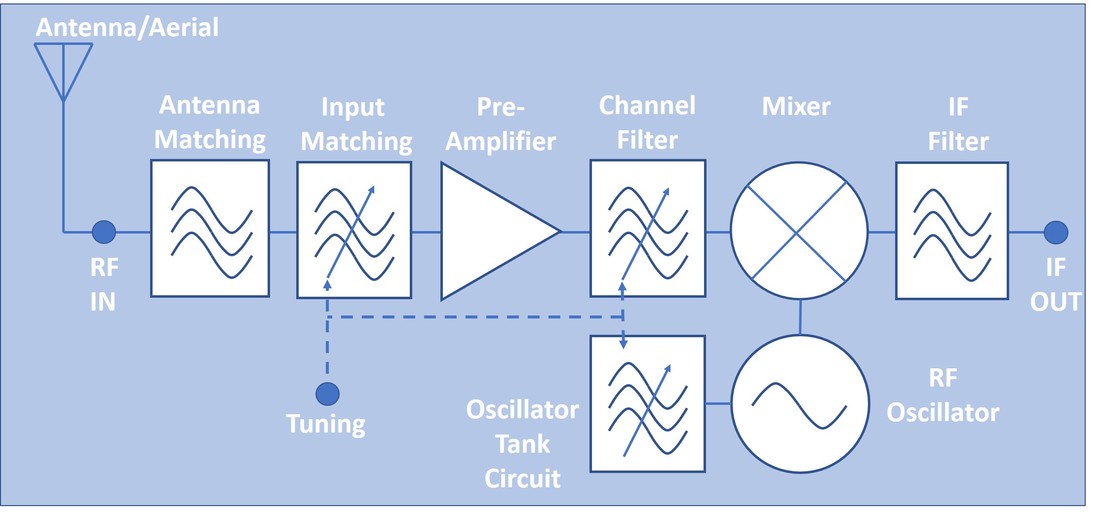
Figure 1 The basic block diagram of a Television Tuner. It contains three active elements: a pre-amplifier, an oscillator and a mixer. All other blocks represent filters of different sorts, where three of them are variable ("tuned").
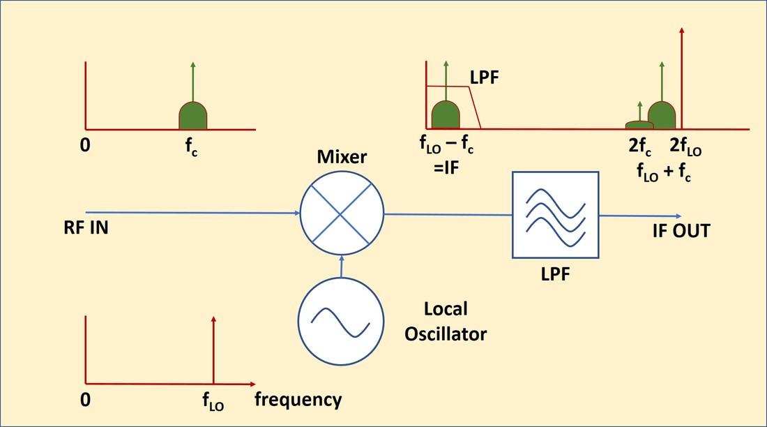
Figure 2 The elementary down-conversion concept of a so-called super-heterodyne receiver as used in all TV tuners.
|
First generation non-tuning television receivers, 1947-1950
For the first years of television broadcast the situation was still straightforward: in principle the owner of a television set was able to receive signal from exactly one transmitter. In the UK this was either Alexandra Palace in London or Birmingham, in France Paris (from the Eiffel Tower) or Lille, in the Netherlands initially the Philips Experimentele Televisie from Eindhoven, later Lopik/IJsselstein. The RF receivers of the first generation post-war televisions where thus set to the single RF channel transmitted in the area where the set was sold. So although some filtering did take place, the basic concept of the television receivers of the Philips TX380, TX390 and TX400 platforms (from 1948, 1949 and 1950, respectively) was as shown in Fig.2.
|
The first post-war commercial television sets from Philips were the 463A and 563A, for the 405-line UK market and designed by the Mullard Labs in Mitcham, South London. It was a 1946 design and clearly based on pre-war televisions. The 463A was a television-only, but the 563A combined television and radio reception. To this end it had the unique concept of separate mixer-oscillators for both video and sound, allowing the sound MO and IF chain to be shared between television and radio mode. This resulted in a very complex arrangement of tuned circuits for four (!) bands around the sound MO. Clearly this was a too radio-centric design, essentially a television built around a radio instead of the other way round, and this concept was never re-used in any other Philips TV set.
|
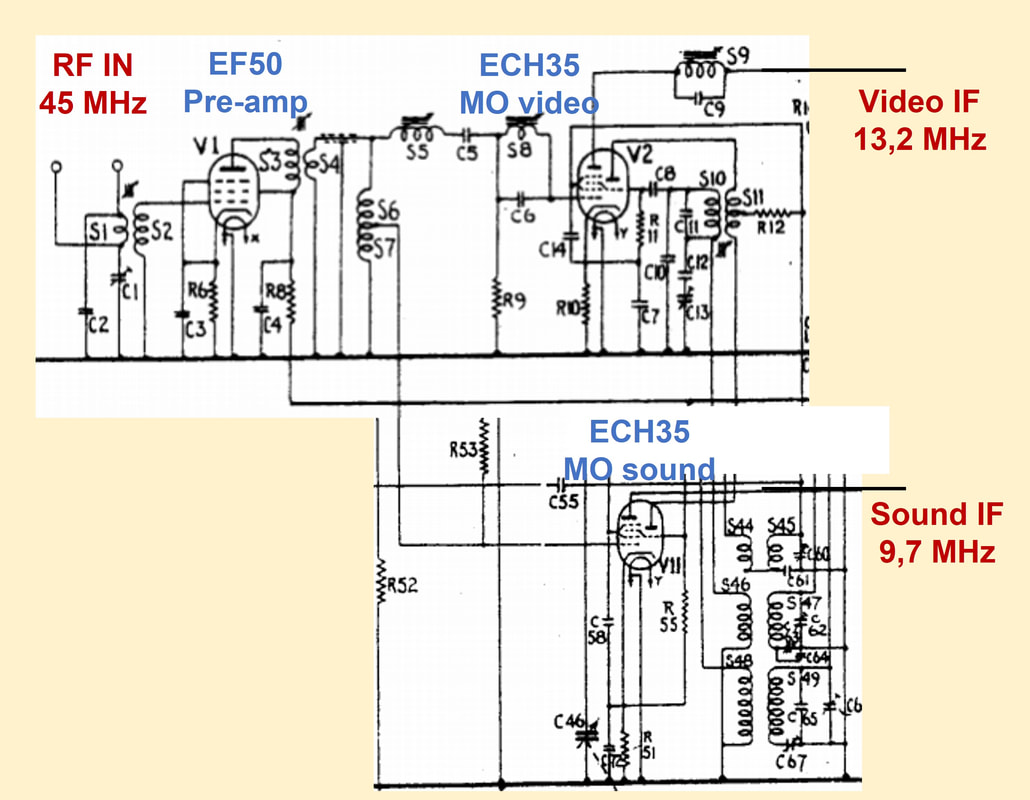
Front end of the Philips 563A, a single-channel receiver for the UK 45MHz Alexandra Palace transmissions, but in combination with a three-band radio. The TV sound and radio share the lower ECH35 MO. [Philips 383A-683A Service Manual]
|
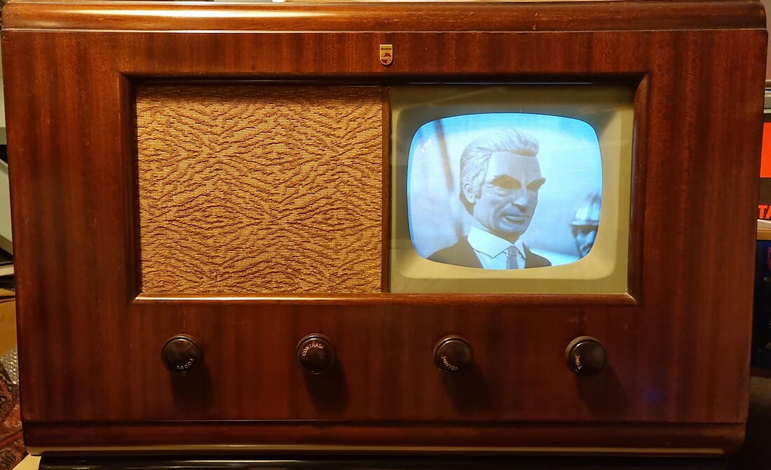
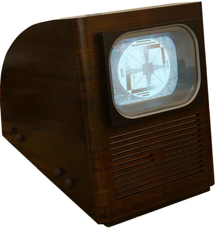
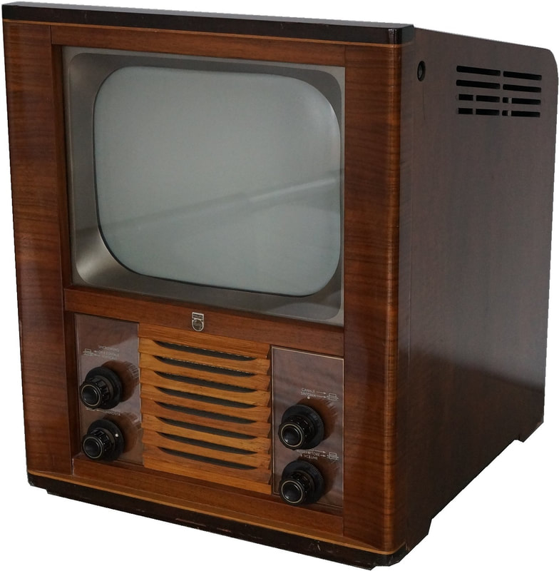
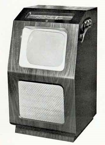
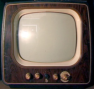
One of the very first commercial Philips TV sets, the 563A 405-lines UK set. Still in working condition. [Jac Janssen]
|
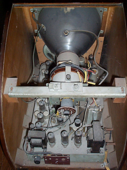
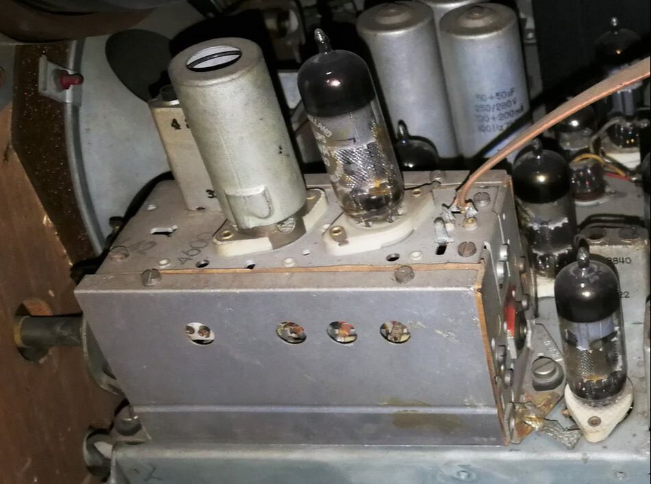
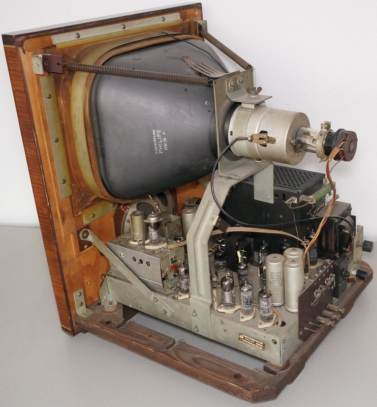
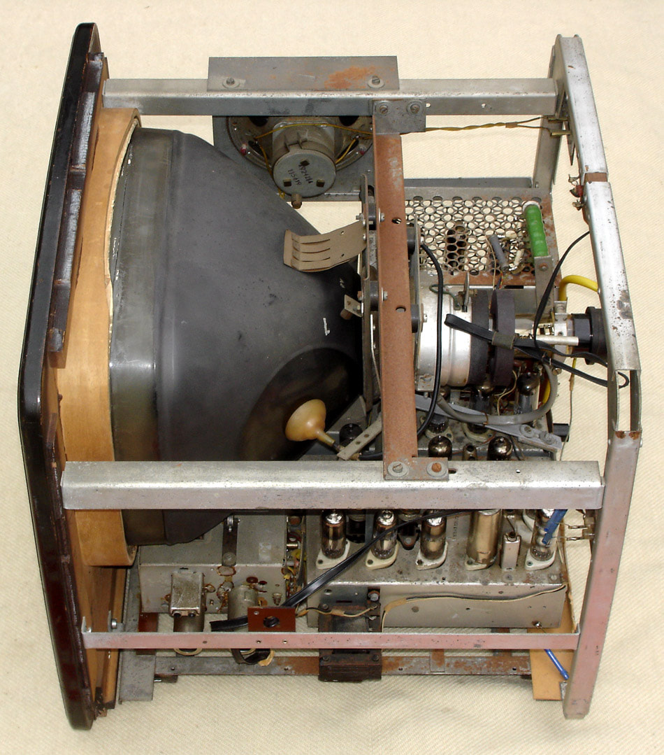
Backside interior view of the 563A. One of the RF ECH35s is visible in the centre, the other is behind the vertical screen to the right. [The Valve page]
|
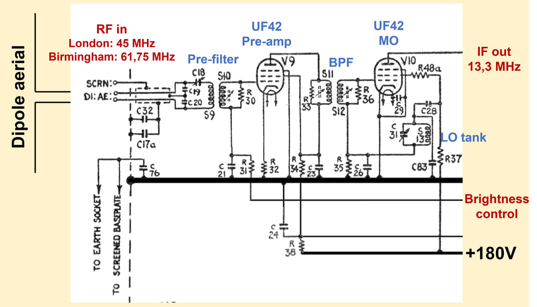
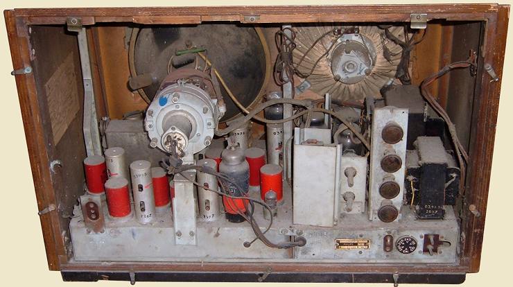
The RF front end section of the Philips 385U from 1949. It was not tunable, and able to receive - depending upon the alignment - either London or Birmingham transmissions. [Philips 385U Service Manual]
|
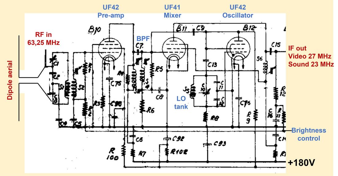
The picture left shows the RF receiver front end of the Philips 385U, a set for the UK from 1949. It was based on a platform design by the Apparaten Lab (Devices Laboratory) in Eindhoven but product development was done in the Mullard Labs in Mitcham. It also introduced the much more compact 40-series Rimlock valves. The set was produced in two versions, one for London, where the Alexandra Palace transmitter station used the picture carrier frequency of 45MHz, and one for Birmingham, with a transmit frequency of 61,75MHz. In case the TV owner moved from one region to the other the set had to be re-aligned in a service work shop.
|
From the circuit diagram we can see that the amount of filtering in this front end was still minimal. At the input is a matching network to transform the 300 Ohm antenna impedance to one better matching the UF42 g1 input impedance. There is a tuned Band Pass Filter (BPF) between the first and second stage, while a single-tuned serial filter S13-C31 in the feedback loop of V10 sets the oscillation frequency of the self-oscillating mixer in the second UF42 pentode. The gain of the first amplifier could be adjusted through the voltage of the line marked "Brightness". This was connected to a potentiometer for a fixed setting, and thus not an Automatic Gain Control (AGC); that would come only later. A front end as shown here was the most basic form of receiver.
The Philips 385U UK TV receiver from 1949. It was already a quite compact, well-engineered chassis. [Jac Janssen collection]
|
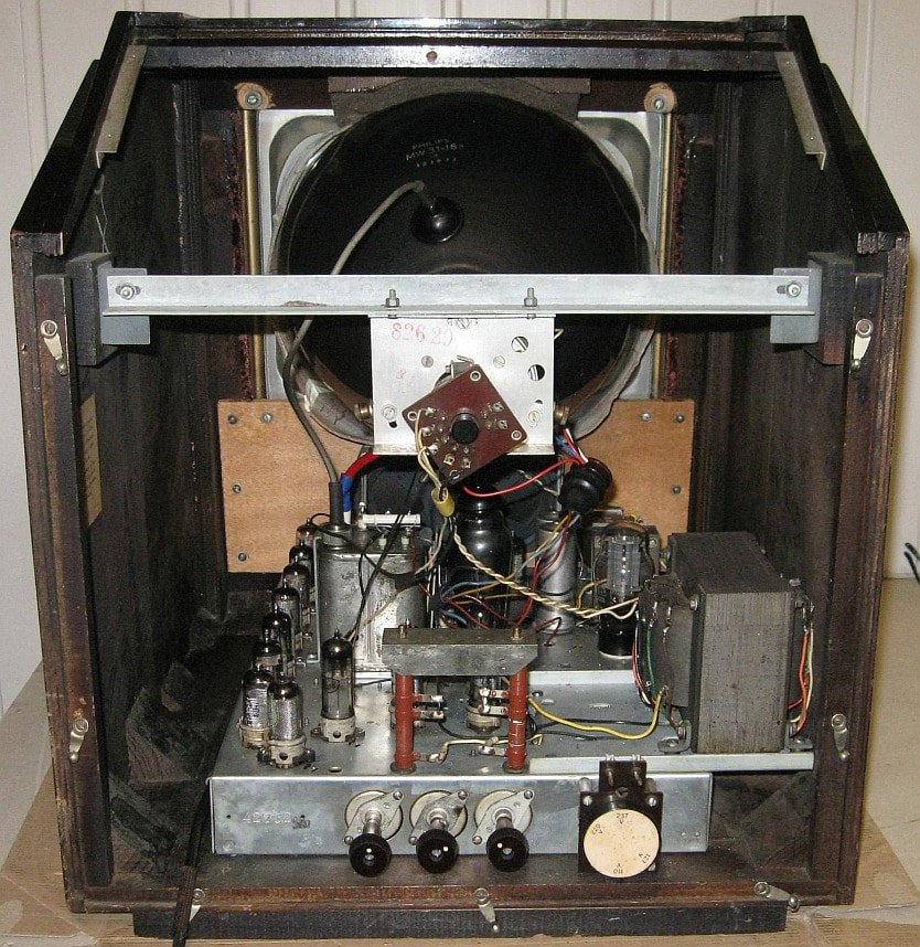
Rear interior view of the Philips 385U, using the compact Rimlock valves. [Vintage Radio & TV Forum]
|
|
A one step more advanced concept for a single channel receiver is shown here, the front end of the TX594U 625-line set. The input stage B10 (using an UF42) is almost identical to the one above of the 385U. However, the mixer and oscillator functions have been separated at the expense of an additional UF42 pentode (B12). The oscillator is a Colpitts, with direct (positive) feedback from g2 to g1 through a tuned circuit S9-C10-C11-C12. Through C9 the oscillator signal is fed directly to the g1 of the UF41 mixer (B11). In theory this arrangement should be optimal for performance; every function properly separated for maximum isolation and minimum crosstalk. At the same time the cost is high (three pentodes), so it will take another three years before we see it back in standard tuners.
|
RF front end of the Philips TX594U from 1949, the experimental set originally designed for the Philips 567-line standard, but in 1949 converted to 625-line reception. [Philips TX594U Service Manual]
|
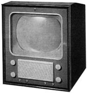
The Philips TX594U from 1949, in fact an experimental set for the local Eindhoven test transmissions. [Technisch Museum]
|
In practise the oscillator of the TX594U seems not to have been very good, despite its dedicated pentode. Especially when the set heated up it had the tendency to run away in frequency. At the time television sets didn't yet contain Automatic Frequency Control loops, and oscillators had to be intrinsically stable, but apparently they were not. Many of the surviving sets thus had additional variable capacitors with an external knob on the side of the set for corrective tuning.
|
Interior view of the TX594U with all Rimlock valves mounted on a single chassis. [RadioMuseum.org]
|
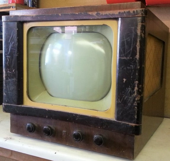
The TF651A for the new 819-line French standard. Note the neat line up of the signal chain valves on the left. [Jac Janssen collection]
|
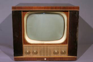
Front end of the TF651A from 1950, the first Philips set for the new French 819-line standard and the first front end operating in the VHF-III band. [Philips TF651A Service Manual]
|
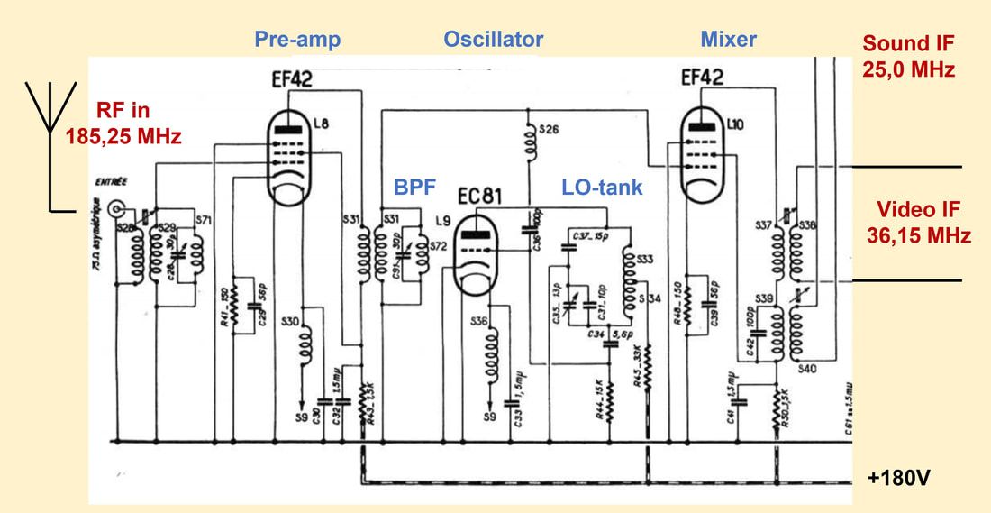
A similar but slightly cheaper implementation of this concept was used in the TF651A, the first Philips television set for the new French 819-line standard. But instead of a pentode it used the cheaper EC81 triode, a valve not applied in any other Philips TV set. The French standard posed a number of challenges: it was the first to use the VHF-III band (the Paris Eiffel Tower transmitted at 185,25MHz), and secondly it had much higher bandwidth (14MHz per channel). Especially to cope with the latter requirement, the picture-IF of the TF651A was moved up to 36,15 MHz. (For comparison, the IF of the previous three receivers was around 13MHz). Finally it is noteworthy that the front end was designed for a 75 Ohm asymmetrical antenna, as opposed to the standard 300 Ohm dipole.
|
Tuner Basics 2: Channel selection
|
The reception of RF signals becomes more complex in case multiple channels are transmitted. Fig.3 shows a simplified picture of a frequency band allocated to television transmission, here containing five channels. [The VHF-I band for CCIR-B standard signals contains 4 channels E1-E4 of 7MHz channel width, and thus runs from 41 to 69MHz]. The picture assumes channel 3 is the wanted channel, so the local oscillator is set to a frequency IF (around 30MHz) higher than the picture carrier frequency of channel 3. Channel 3 will thus be converted to fit exactly in the fixed IF band pass filter. However, because the RF channels are all present at the input of the mixer they will all be down converted, albeit in reversed order (see the bottom graph).
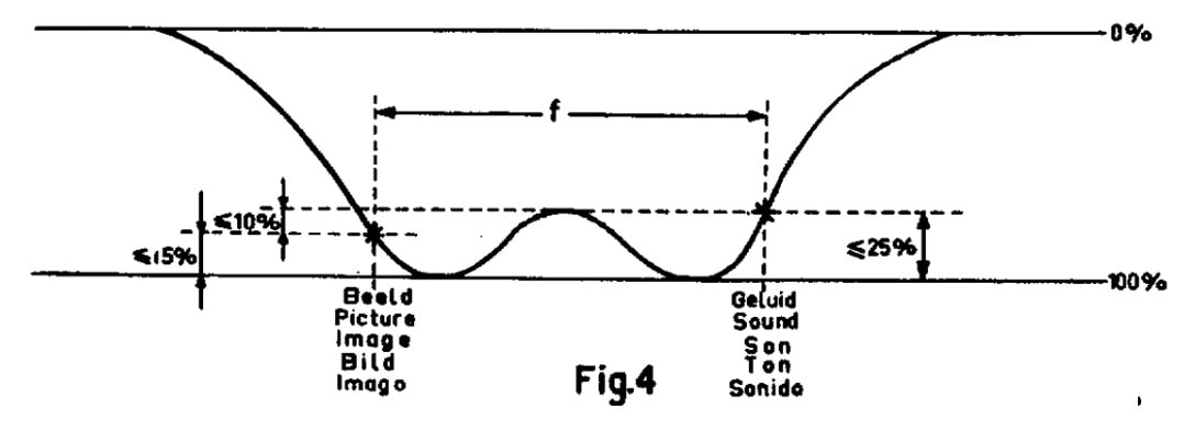
The problem is that the practical IF filter in (early) TV receivers was far from as narrow as suggested in Fig.3. When the IF BPF is broader, adjacent channels from the wanted one will consequently also appear in the IF and video chain of the set, leading to distortion in either picture or sound. The remedy to this is RF filtering or channel filtering, as much and as early as possible in the receiver. This is shown in Fig.4. In practise this RF filtering would be achieved through the combined effects of the tuned input matching and inter-stage BPF, see Fig.1. The amount of reduction of the adjacent channels is usually referred to as "Selectivity"; the higher the selectivity, the better the tuner. |

Figure 3 Down conversion in the situation of a fully filled television frequency band with five channels, and without RF filtering. In this example channel 3 is the wanted channel.

Figure 4. Down conversion in case of a fully loaded frequency band, but now with RF filtering. Although the IF filter is also depicted in a more realistic way, the combined filtering of the RF and IF filters gives a substantial attenuation of the unwanted adjacent channels.
|
The last step to come to a real tuner is tuneability. From Fig.4 it is clear that it is drawn for the situation of channel 3 as the wanted channel. In case another channel is wanted, say channel 1, both the Channel BPF and the LO need to centre on that channel, which means that their centre frequency needs to reduce by two channel widths. In VHF-I for CCIR-B this would be 2x7=14MHz. This operation is called "Channel Selection" or in practise "Tuning", an expression dating from the earlier radio days, from which the name of the function is derived: "Tuner", although officially it is of course "Channel Selector". "Kanalwähler" in German, "Kanaalkiezer" in Dutch and "Sélecteur de Canaux" in French.
The first 4-channel tuner, 1951
The TX400U-00, the first version of the TX400U, the very first commercial 625-line "Gerber-norm" television, still contained a single-channel front end as in the first generations. As such it was launched in 1950, just before the start of 625-line TV transmission in The Netherlands. But already the next year an updated version was introduced, the TX400U-01, containing the first real tuner. Simultaneously this module was introduced in the standard version of the TX500U (with 12" display) and TX700U (a large screen rear projection model). The first 4-channel tuner was coded A3 421 82 (used in the TX400U-01 and TX500U-00) and had an asymmetrical 75 Ohm input, but it was quickly superseded by the A3 694 42 with a 300 Ohm symmetrical antenna input (it was implemented from the TX400U-04 and TX500U-04 versions). These tuners introduced a few important innovations:
1. Multi-channel tuning, in this case 4 channels
2. A dedicated tuner module. Until then the RF front end was simply built on the main chassis as part of the integral RF-IF-video/audio chain. In most cases there had been no RF shielding of the tuner section. With the A3 421 82 a dedicated tuner module was introduced, placed on top of the chassis, and providing proper RF shielding.
3. Noval valves, in this case the EF80, replacing the Rimlock EF42 or UF42. This didn't necessarily mean a major performance improvement, because neither the EF/UF42 nor the EF80 were dedicated RF valves; they were both essentially IF and baseband valves.
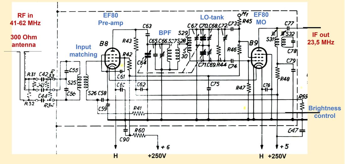
The Philips A3 694 42 4-channel tuner, used in the TX400-platform from 1951. This was the 300 Ohm input version, replacing the 75 Ohm version A3 421 82, which was identical apart from the input matching circuit. [Philips TX500U Service Manual]
|
Comparing the circuit diagram of the A3 694 42 with the previous single-channel front ends, we see that it has increased in complexity, although the input matching, the brightness control through the g1 voltage of B8 and the output filter remained more or less unchanged.
For this first tuner the designers had chosen capacitive tuning. So the inductors of the BPF channel filter (S27-S28) and the oscillator (S29+S30) were fixed, while the channel tuning was accomplished by simultaneously varying the BPF capacitor C64 and the oscillator tank circuit capacitors C70 and C71. |
The complexity of the tuning function should not be under-estimated. For tuning from channel 1 to 4 in the VHF-I band the BPF central frequency has to move from 43,5 to 50,5, 57,5 and 64,5MHz, while the LO frequency moves from 80,15 to 87,15, 94,15 and 101,15MHz. (In the TX400 platform the picture carrier IF was 23,5MHz). For each of the channels the error between the desired BPF centre and the LO should not be more than 100-200kHz to avoid picture or sound distortion. Especially the BPF had to tune in a linear way over a range of more than 30%, the LO more than 20%. It is thus not surprising that around the BPF and especially the oscillator there are a number of trimmers to guarantee a smooth and constant joint tuning of the BPF and LO. C66, C69 and C72 were all adjusted in the factory for optimal alignment at the upper edge of the band, and were trimmed at 64,5 and 66,75MHz. Other alignments were the IF output filtering, where S31 was tuned to the centre of the IF pass band (19,75MHz) and S32 was a trap at the picture carrier of the next channel (23-7=16,5MHz).
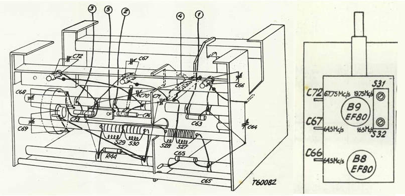
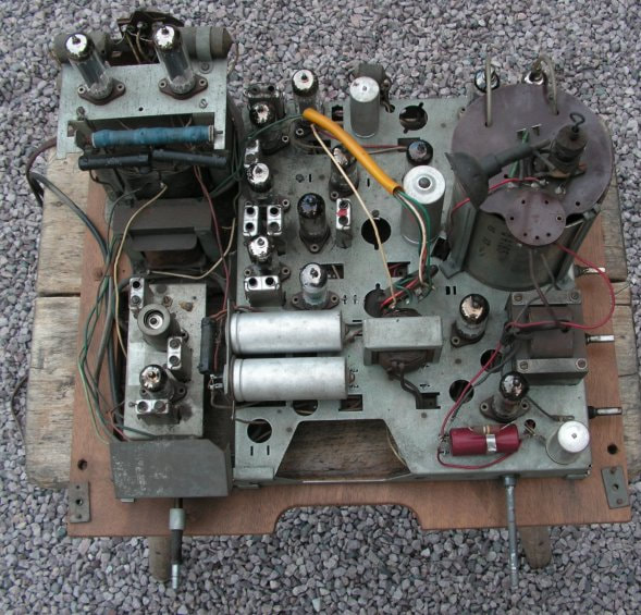
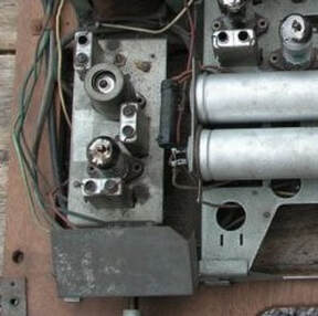
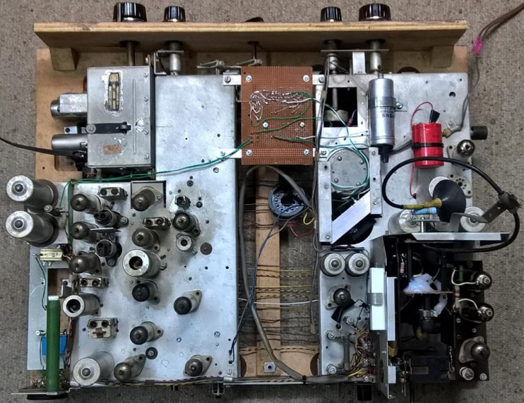
Interior and top view of the Philips A3 694 42 4-channel capacitive tuner. The core BPF and LO inductors are mounted on a common rod for magnetic coupling. The compartment on the right contains the input circuit, pre-amplifier and BPF and is shielded from the compartment on the left containing the LO, mixer and IF output. The picture on the right shows the three capacitive and two inductive alignment points of the tuner. [Philips TX500 Service Manual]
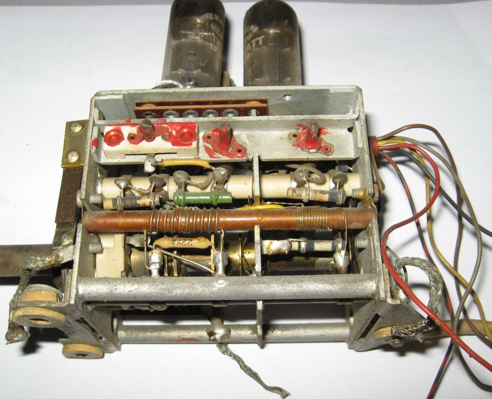
Interior view of the Philips A3 421 82 4-channel tuner as used in the TX400U/04 version. The picture can easily be compared with the drawing above. [Jac Janssen collection]
|
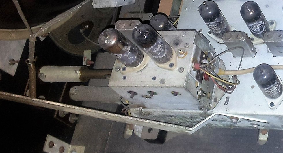
Picture of the Philips A3 421 82 4-channel capacitive tuner with two EF80's in the TX500U/10 television. [Maurice Hamm collection]
|
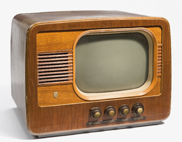
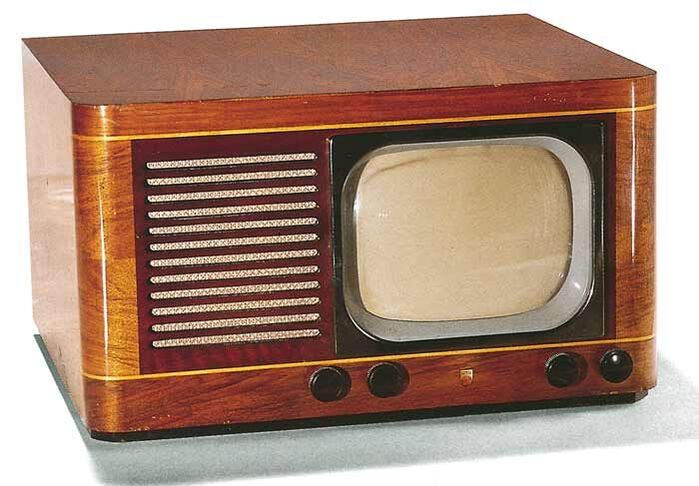
The TX400U, the first "Gerber-norm" Philips television from 1951, and also the first equipped with a (4-channel) tuner. [Technisch Museum]
|
Interior view of the TX400U, with lower left the tuner and its two EF80 valves. [ibid]
|
The Philips TX500 featured a larger 31cm (12") screen but was otherwise identical to the TX400U, including the tuner. [ibid]
|
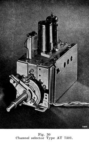
AT7501, 10-channel capacitive tuner, 1952
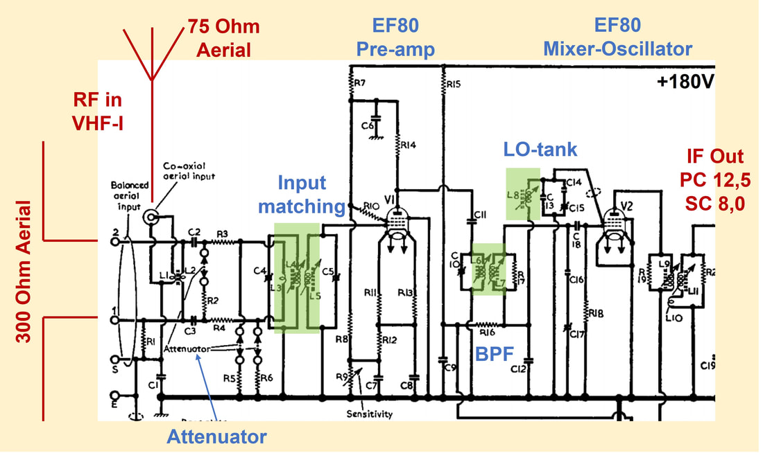
Already the next year, 1952, yet another upgrade appeared: the 10-channel capacitive tuner AT7501. It obviously was not possible to tune across the combined VHF-I (40-68MHz) and VHF-III (174-223MHz) bands, and therefore the tuning range was split into two sections, one for each band. Because combining a dual band tuner with a self-oscillating mixer-oscillator made it all too complex, the first modification was the introduction of the ECC81 as mixer-oscillator; one triode acting as oscillator, the other as mixer. The EF80 pre-amplifier remained essentially unchanged. Because it is impossible to match antenna impedance to the EF80 input impedance over the combined VHF-I and III range, also the input stage now became not only band-specific but also tuned. As a result the tuner was the first to have three jointly tuning circuits (input match, BP channel filter and oscillator tank circuit), and all three of them duplicated for VHF-I and VHF-III. A switch linked to the capacitor stepping mechanism would would flip between channel4 (VHF-I) and 5 (VHF-III).
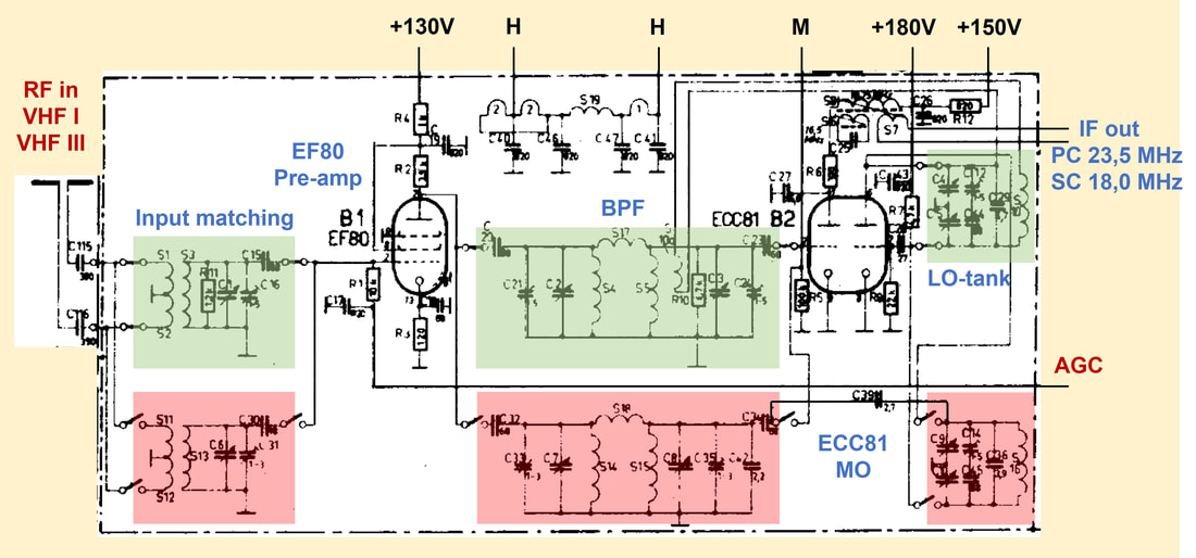
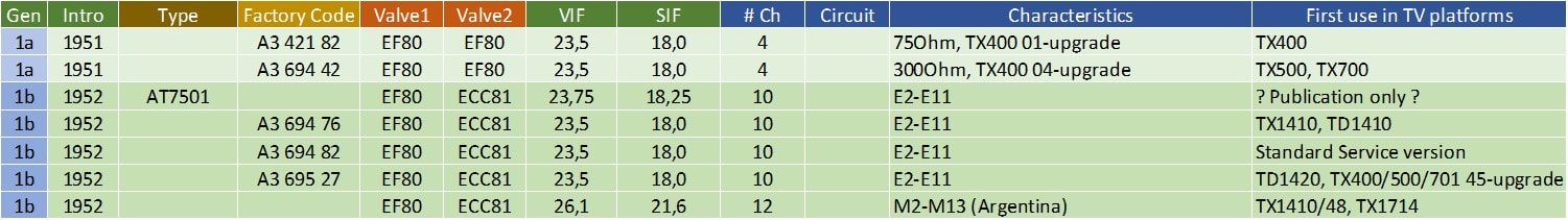
The Philips AT7501 2-band 10-channel capacitive tuner. The green tuned circuits are for VHF-I, the red ones for VHF-III. The contrast control was now part of an AGC-loop from the video detector. Measuring point M is only used during factory alignment. [Philips TD1420U Service Manual]
|
[Philips series "Electronic Valves", Book 3C, J. Jager, 1953]
|
|
The schematic on the right, from the TX1410U television, is clearer in showing the concept of the tuner (although this one is less clear on the switching, for that the TD1420 tuner diagram is better). The green and red zones show the different ways of oscillator-to-mixer coupling. For VHF-I (green) it is done inductively, with a small coil S10a coupling into the secondary of the BPF. For VHF-III it is done capacitively using C39. Also note that the IF output uses galvanic decoupling from the tuner through S7, a concept so far only used in the TF651A tuner.
|
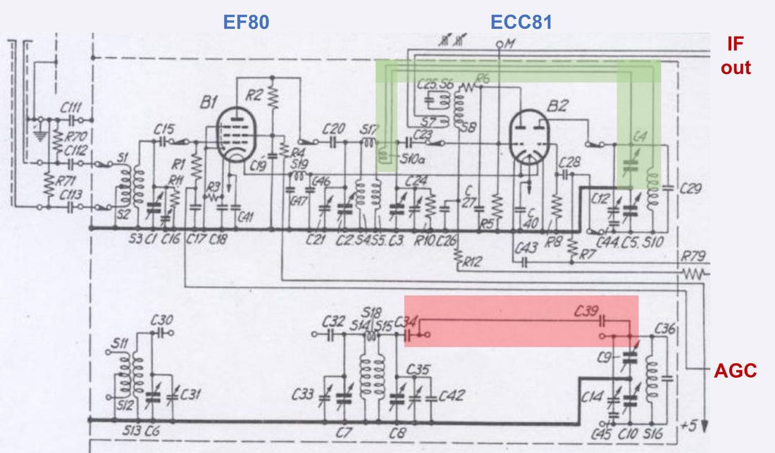
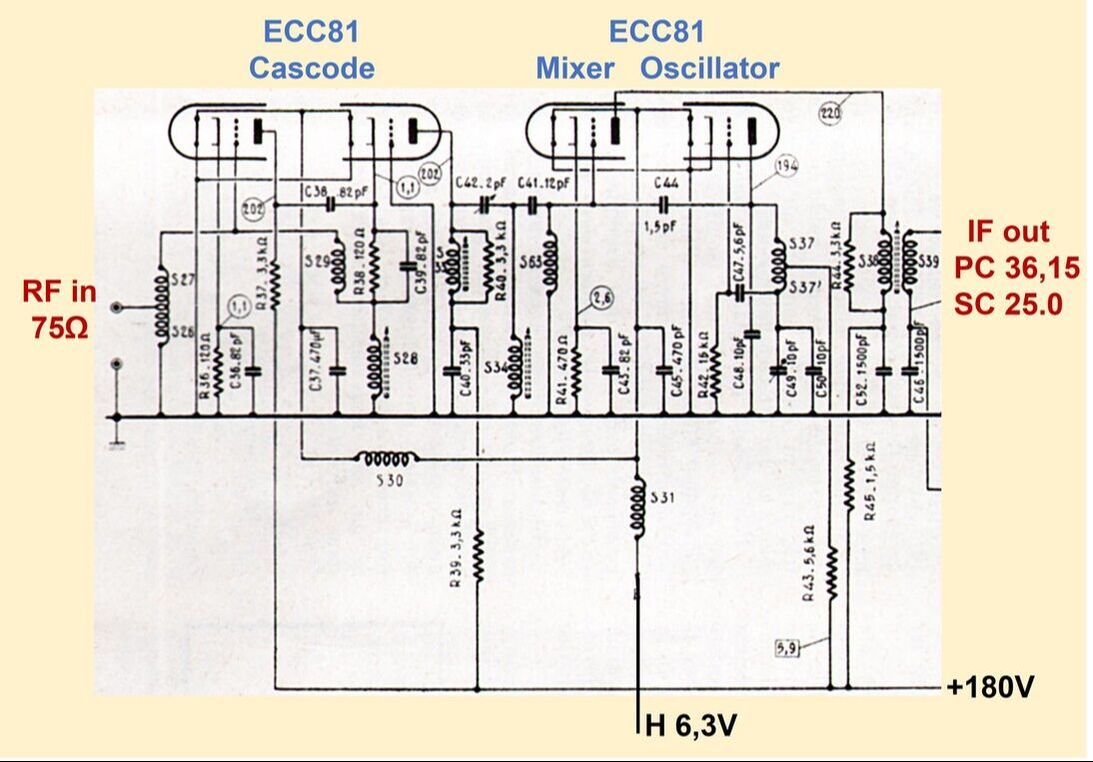
The Philips AT7501 tuner as shown in the TX1410U television schematic. It clearly shows the different ways of oscillator-to-mixer coupling for the two bands. [Philips TX1410U Service Manual]
|
One of the new functions the AT7501 needed, in the meantime, was band switching. In the above circuit diagrams is visible that the input matching filter, BPF and LO tank for each band VHF I and VHF III were switched with 7 switches each, so 14 in total! (The TD1420 schematic diagram is again the one illustrating this best). The question is how these 14 switches were operated. To this end the AT7501 introduced a first of many mechanical innovations that we will see in the coming generations of (VHF) tuners. Mechanical designers were at least as important in tuner design as electrical engineers, and tuners will increasingly be superb multi-disciplinary technology solutions!
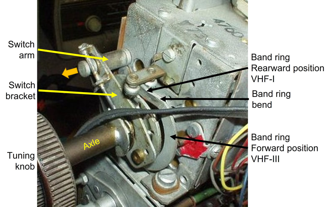
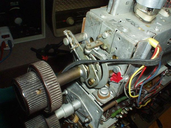
Close-up view of the AT7501 2band tuner band switching mechanism. [picture RadioMuseum.org]
|
The AT7501 band switching assembly, as visible in the picture on the left, can be described as follows. On the tuner axle, which is rotated by the front panel tuning knob, a bended band ring is mounted. For VHF-I the ring is "high"as shown on the picture, for VHF-III it bends to a lower height. This ring runs through fixed wheels, mounted on the tuner frame. When turning the axle through the band switching position, the lower height of the ring will force the entire switch assembly forward along the axle axis. This movement is transferred through the switch bracket to the switch arm, which will move outward as shown by the yellow arrow. Inside the tuner the 14 switches are mounted, where for each position of the swith arm (in and out) seven switches are closed.
|
The AT7501 inside the TX1410U TV. The EF80 is uncovered, but the ECC81 has a grounded shielding cap mounted. [via Taco Vonk]
|
Full view on the AT7501 band switching assembly. [RadioMuseum.org]
|
The AT7501 was used from 1952 in the TX1410 platform, with the main family members TX1410, TD1410, TX1714, TD2314 and TD1420. Also the earlier TX400, TX500 and TX700 received field upgrades using this tuner, which had factory code A3 694 76 and (with slight modifications) A3 695 27. The IF used in this platform was still 23,5MHz picture carrier and 18,0MHz sound carrier, with two remarks; firstly in volume 3C of the "Electronic Valves" series of Philips from 1953, the AT7501 is used in the reference diagram of a 625-line television receiver with IF's at 23,75 and 18,25MHz, for picture and sound, respectively. It is unclear where this comes from, and as far as I know these values have never been used in a real TV set. I therefore still hesitate whether the AT7501 and A3 694 76 are 100% the same or not. Secondly, two later sets of the TX1410 platform, the TX1410U-48 (an NTSC set for Argentina) and the TX1714A both introduced slightly higher IF values with a picture carrier at 26,1MHz and sound IF at 21,6MHz (the TX1410U-48) and 20,6MHz. As far as I can see these were the only two sets using these values, which was almost certainly an intermediate step towards the new higher IF at 38,9MHz that would come with the next generation.
The Philips TX1410, the first TV to feature a 2-band VHF tuner. [Technisch Museum]
|
Conceptually the TX1410 was still very much the same platform as the TX400 and TX500. [Technisch Museum]
|
The TD1420 for the German market was a new design, with a different internal construction.
|
Although it introduced the 10-channel tuner, the AT7501 was still a mediocre solution because of one specific item: the EF80 simply was no RF valve. There were two reasons for this. The first and fundamental issue is that pentodes are simply noisier than triodes. Because part of the electron flow out of the cathode is received by the screen grid g2, at the anode this results into "missing electrons" with a statistical behaviour, which can be translated into an additional effective noise contribution. But secondly the EF80 was primarily an IF valve, with higher parasitic capacitances due to the larger grids, that had a negative effect on its high frequency gain and noise performance. Noise Figure was therefore particularly bad, and in practise the EF80 was often replaced by the fully compatible Telefunken EF800, which had considerably better noise and microphony performance. Telefunken, however, was the biggest European competitor of Philips and it was against all corporate policies to use their valves. These were therefore imported by the Philips Sweden organization for delivery to the local Service organizations. Clearly this needed an internal solution.
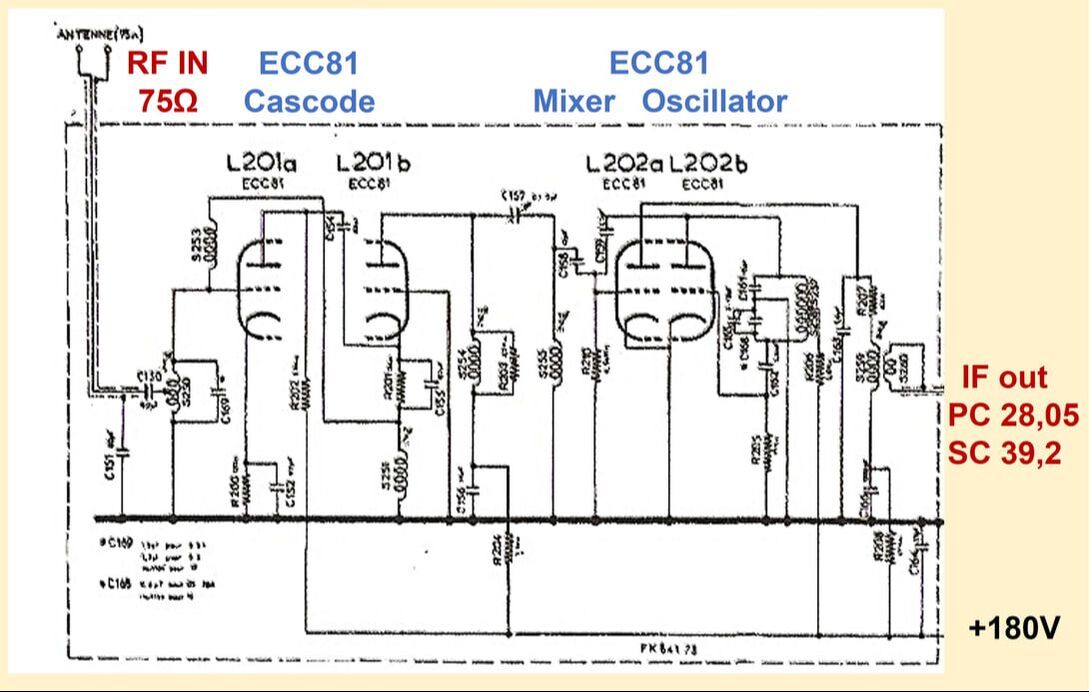
Overview of the first generation Philips 4- and 10-channel capacitive tuners. Because of the narrower channel width for Argentina (standard M) even 12 channels could be covered.
French and British front ends and tuners, 1951-1954
Developments in France and Britain during the first half of the 1950-ies were different from those in the CCIR-B countries Netherlands, Western Germany, Scandinavia, Switzerland, Italy and (with modifications) Belgium. The main reason for this were the unique and local standards: 405 lines in the UK, 819 lines in France, with limited need, desire or possibility to receive TV transmissions with different standards. Furthermore, since both countries were large it took longer to obtain full coverage, and new transmitters were often far apart; e.g. in France the order was Paris, Lille, Strasbourg, Lyon and Marseille. Only in 1956 did the roll out of more regional transmitters start. Britain had a similar roll-out. Because all stations transmitted the same program, owners of a TV set were expected to select the strongest one for reception, and TV sets were thus assumed to need only a one-channel receiver. In practise this meant that a basic TV chassis could be equipped with a set of channel-specific coils in the factory, making it a regional receiver. When owners moved home to another region the TV set had to be modified to the new regional frequencies in a service workshop.
|
Until 1950 the RF front ends of the television front ends were all based on dual pentode solutions, two times UF42, EF42 or EF80. We've seen earlier that the performance of these tuners was mediocre at best. The first to introduce a more dedicated valve was the French tuner development. Linked to the roll out of the new 819-line standard from 1951, with its 14MHz channel bandwidth, a much better performance was required, and a new front end based on two ECC81's was introduced. Remember that the AT7501 tuner introduced simultaneously in Eindhoven only used the ECC81 for the mixer-oscillator. Also this French front end was the first to introduce the cascode input circuit.
At the same time it was not a tuner, but a fixed single-channel front end, built on the main chassis of the television. This concept was introduced in 1951 with the TF652A, the first Philips 819-line set developed in France, followed by the TF2323 rear projection TV and then the TF1420 and 1720 platform, the local version of the TX1410. But the "single channel front end on the chassis" concept came to an end, and in 1952 the front end function - still not a multi-channel tuner! - became available as a module or bloc monocanal, but still based on an almost identical circuit diagram. These blocs were factory-aligned for a single specific channel, and could easily be exchanged when needed. Initially a single model was required, serving French channel F8a (vision carrier 185,25MHz) of the Paris and Lille transmitters, later the Strasbourg version for channel F6 (174,30MHz) came available. In parallel the bloc also introduced the final French IF values, but these will be explained further down. In 1954/55, with the TF1746, the bloc monocanal was replaced by a then standard 12-channel tuner module. |
The new front end for the French 819-line Philips and Radiola TV sets. Also note that French sets were mostly designed for 75 Ohm co-axial antenna connection, as opposed to the 300 or 240 Ohm symmetrical balanced antennas used in the Netherlands and Germany. [Philips TF1426 RT3626 Service Manual]
The single channel front end module (bloc monocanal) as introduced in the TF1435 in 1953. This is the FK 841 73 as used in the TF1446. [Philips TF1446 Service Manual]
|
Top view of the French Philips TF1435 TV. A single chassis contained all electronics except on the left the RF bloc monocanal (below) and the power supply (above).
|
Close up of the bloc monocanal RF unit with its two ECC81 dual triodes. [All pictures from Rétro Forum]
|
Bottom view of the bloc monocanal as mounted on the wooden bottom plate. This clearly shows it was essentially a U-shaped support structure, not an enclosed box, and with no mechanics since it was not tunable.
|
Three generations early French Philips TVs. This is the TF390A from 1949. No tuner, single channel RF on the main chassis. [Musée Radio RTF]
|
The Philips TF1726 from 1952, still no tuner but single channel RF using two ECC81 on the chassis. [Blazianu]
|
The Philips TF1736 (or Radiola RA4336A) from 1953, using the bloc monocanal single-channel receiver module. [Blazianu]
|
In the UK developments were similar, although not identical. Like in France the front end function remained initially on the main chassis, where the British Mullard-designed chassis tended to have two separate chassis sections: one for small signal (RF up to video output) and one for large signal (synchronization, deflection and HV generation). The design remained based on the two EF80's, so not using the cascode input stage. Channel-specific implementations were made using three replaceable coil modules. These modules fitted in standard B9A/Noval valve sockets, were factory-aligned and colour coded, and during set alignment they were not to be touched or changed. Modification of a TV set from one regional channel to another thus meant replacing the three coil modules. This concept was used from 1951 (the 1100 family) until 1953/54 (1400 and 1700 families). By that time a customer could choose between basic modules with the single-channel frontend or optional 12-channel tuners (the AT7520).
The RF front end of the Philips 1114U 405-line UK television set from 1951. In contrast to the Dutch and German sets (300 Ohm balanced input) and French sets (75 Ohm asymmetrical input) the UK sets supported both. In case of very strong signals attenuators (R5 and R6) could be inserted. Sensitivity could be adjusted using potentiometer R9. The three channel-dependent replaceable coil modules are indicated in green. [Philips 1114U Service leaflet]
|
Picture of the Philips 1200U small signal chassis, with on the right the front end valves and replaceable coil units. [UK Vintage Radio Repair Forum]
|
Three generations of UK Philips television. This is the 520A with 9" screen from 1948. No tuner, single channel receiver with EF50 and CCH35 on the chassis. IF PC at 13,3MHz, SC at 9,8MHz.
|
The Philips 492U with 12" screen from 1949. Single channel receiver using two UF42 Rimlock valves on the chassis. IF increased 100kHz to 13,4Mhz PC, 9,9MHz SC. [UK Vintage TV and Radio Forum]
|
Philips 1101U from 1950, still with 12" screen. It used two EF80 valves for the receiver, which used lower IF values of 12MHz PC and 8,5MHz SC. [The Valve Page]
|
All in all it is surprising to see that in both the UK and France the Mullard and La Radiotechnique TV design centres were much more conservative in introducing higher IF values and/or multi-channel tuners compared to their colleagues in Eindhoven and Krefeld. The main explanation for the multi-channel tuner is probably that, due to the deviating 405 and 819-line standards, there was not even the possibility to receive transmissions from other countries, this in contrast to Germany, the Netherlands, Belgium and Switzerland which all had neighbouring countries with (almost) identical standards and programs that people wanted to receive. In France and Britain there was initially only one program transmitted, without the need for multi-channel tuners. Tuners were only introduced once multiple programs were transmitted, especially in the VHF-III band.
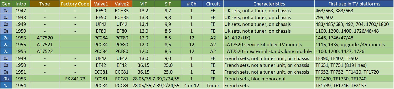
Overview of the British and French front end and tuner solutions between 1947 and 1955, when the Philips TV design centers in both countries finally introduced the standard 12-channel rotary drum tuner.
Tuner basics 3 - Choice of Intermediate Frequency
|
The choice of IF frequencies used in a TV receiver was initially left to the set maker, where every brand applied its own design considerations. These were especially determined by the capability to design circuits with the required performance, and first IF's were thus invariably between 6 and 13MHz. As long as only one single TV channel was transmitted selectivity was not a major issue, but when more VHF-I channels were introduced performance was no longer good enough. Many set makers now used different IF values for different channels, others moved to high VIF frequencies in the 16-23MHz range.
With the increasing number of channels, so did the problem of interference grow. All this is fundamentally related to the non-linear mixer performance. For the down conversion action (shifting the signal Radio Frequency to a (much) lower Intermediate Frequency, see Tuner Basics 1) a non-linear function is required: a multiplication in the time domain (equivalent through Fourriers theorem to a translation in the frequency domain). This non-linear function is obtained through the characteristic of an active element: a diode, triode or pentode (and later of course the transistor). The problem is that the non-linear characteristic is not a perfect multiplication (Vin + Vlo)^2, that would give the output frequencies flo-fin and flo+fin, but a more general characteristic (Vin+Vlo)^n, where n can be a mostly non-integer number between typically 1,5 and 3. This means that the output of the mixer becomes a - theoretically infinite - range of combinations of harmonics of the input and local oscillator frequencies. At the same time the mixer is driven to higher non-linearity by the LO voltage, because the IF output signal strength is proportional to Vrf*Vlo. Since Vrf is low (the weak received signal) Vlo must be as large as possible. But this in turn drives the mixer to large voltage swings and thus high non-linearity. Fortunately many of the harmonics generated in quickly become irrelevant in practice, the amplitude coefficient of the harmonics are proportional to the multiplied amplitudes of their contributing signals, and thus diminish rapidly. This is further strengthened by the selectivity of the circuits and filters around the mixer. For analysis of the interference only the harmonics generated by the strongest signals are therefore of relevance, which are the LO and the IF picture carrier. All harmonics proportional to Frf can thus be neglected. The first issue occurs with harmonics of the IF into the VHF-I band (I will use the CCIR-B standard as reference, so the frequency band for E1-E4 which runs from 40 to 68MHz). These IF harmonics, generated in the mixer, might fold back into the RF input signal path and thus give visible or audible interference since their amplitude might be of the same order as the wanted signal. |

An interesting benchmarking overview of the IF frequencies used in UK 405-lineTV sets between 1947 and 1954, at the time when VHF-III transmissions were introduced and older sets required upgrading. Numbers indicate the Vision IF in MHz, where the SIF is 3,5MHz lower (white fields) or higher (coloured fields). TRF indicates non-heterodyne Tuned Radio Frequency receiver. Three clusters of concepts are visible: high-IF with the VIF close to the formal new System-A BREMA standard of 34,65MHz (yellow, the single one that is on spec is coloured green); low-IF with VIF around 16-19MHz and already SIF-above-VIF (orange); low-IF systems with VIF 12-16MHz and the SIF below (white). It is interesting to see that Philips/Mullard used the lowest VIF of all set makers. [Data from "TV conversion for I.T.A."by CE Lotcho, 1957, Jac Jansen collection]
|
|
As can be seen from Fig.5, when taking the 2nd, 3rd and 4th IF harmonics into account for the 625-line CCIR-B norm, there are only two frequency bands allowed for interference-free IF: below 10MHz and between 34 and 40MHz. Because the range below 10MHz is not practical, e.g. due to overlap with the video baseband and because the LO frequency would be very close to the wanted channel frequency, and likely in-band. All systems thus moved upwards, with the CCIR-B standard (in Western Europe, and even there not all countries) settling on 38,9MHz picture carrier and 33,4MHz sound carrier. With this the IF ended up as close as possible to the lowest receive channel.
|

Figure 5. The effect of (picture carrier) IF harmonics on the VHF-I band for CCIR-B channel allocations. They show that intermediate frequencies between 10 and 34MHz are the "forbidden zone" and only the 34-40MHz band allows an "interference-free" system. Consequently the picture carrier IF of Philips 625-line receivers moved upwards from 13 to 23,5 and ultimately 38,9MHz, which became the standardized Western Europe CCIR-B IF.
|
In this context it is interesting to have a closer look at how the standardization on the 38.9MHz Vision IF took place. Intermediate Frequencies were strictly spoken an internal set issue, and since under normal conditions IF signals did not come outside the TV-set there was no need to standardize them. This meant that every TV-maker essentially determined its own IF values, as shown in the table for the German set makers only. This shows that in 1951 the VIF used ranged from 19,2 to 27,75MHz, with a one-off Loewe set at 37,5MHz (and which could even be a typo). However, the CCIR was pushing for some level of standardization, requesting for proposals by the different countries. This led to multiple proposals for higher Vision IF frequencies from different European countries: 39,5MHz (Sweden and Switzerland), 39,75 (Denmark for future use), and 41,75MHz (Belgium and Denmark).
In this discussion, initially unknown to me, Philips came with what would become the accepted de facto CCIR-B/C/F VIF standard: 38,9MHz. It seems that the analysis was done by Walter Horn (of the Apparaten-lab) and W. Werner of the Philips Research TV group. This analysis was almost certainly based on (probably multi-standard) harmonic interference considerations of especially the LO. A Philips Technical Review article from 1955 says "From interference considerations, it appears that, for the Belgian and Gerber standards, the most favourable IF for the picture is 38,9Mc/s" [PTR Vol17 12-1955 pp.161-170]. The final analysis must have been done around 1952, because only that year the ITU standardized the VHF frequency bands. However, Philips must have started the analysis and design even earlier, because the 1953 families TX1420/1720 and 17TX100 all used the 38,9MHz VIF! In 1953 Holm and Werner published their analysis in the German magazine Ton und Funk. Apparently Philips won over the German authorities and set makers, since by 1954 the 38,9 VIF 33,4 SIF setting was reported as a joint German-Dutch proposal into the standardization discussions.
In this discussion, initially unknown to me, Philips came with what would become the accepted de facto CCIR-B/C/F VIF standard: 38,9MHz. It seems that the analysis was done by Walter Horn (of the Apparaten-lab) and W. Werner of the Philips Research TV group. This analysis was almost certainly based on (probably multi-standard) harmonic interference considerations of especially the LO. A Philips Technical Review article from 1955 says "From interference considerations, it appears that, for the Belgian and Gerber standards, the most favourable IF for the picture is 38,9Mc/s" [PTR Vol17 12-1955 pp.161-170]. The final analysis must have been done around 1952, because only that year the ITU standardized the VHF frequency bands. However, Philips must have started the analysis and design even earlier, because the 1953 families TX1420/1720 and 17TX100 all used the 38,9MHz VIF! In 1953 Holm and Werner published their analysis in the German magazine Ton und Funk. Apparently Philips won over the German authorities and set makers, since by 1954 the 38,9 VIF 33,4 SIF setting was reported as a joint German-Dutch proposal into the standardization discussions.

Overview of the transition to the de facto VIF standard of 38,9MHz by Philips and all German TV set makers.
|
And so Philips was the origin of what became the world-wide standard for CCIR-B/C/F and later also G/H (UHF) standards. However, Philips introduced the new IF well before it was a de facto standard. As we see from the table left, by 1951/52 every set maker was still using its own IF settings. In the first generations TX400 and 500 Philips still used the 23,5MHz - one of the lowest values used! - but clearly was considering a move to higher values. The 1953 sets all moved to the new 38,9MHz, where I expect that the multi-standard 17TX100 was a strong driver for this decision. All in all this meant that Philips was during the 1953 and 54 the only set maker using the 38,9MHz VIF. In parallel the acceptance of this value as the optimal solution stepwise rippled through the German set maker community, with the first five switching over in 1955. Two years later all German set makers had switched.
|
Other standards and countries made similar moves, always determined by the standards characteristics and frequency bands used for transmission. Italy, as an example, although using the CCIR-B 625-line standard, did not use channel E1, and consequently moved the IF upwards to 38,9+7=45,9MHz picture carrier and 40,4MHz sound carrier. The US NTSC standard similarly moved to 45,75MHz, while Eastern Europe CCIR-D ended up at 38,0MHz. The UK CCIR-A ultimately also used the same 34-40MHz band, but with reversed signal allocation; the picture carrier at the lower 34,65MHz and the sound carrier at 38,15MHz. As we've seen already, until these final IF frequencies were settled around 1955, quite some different earlier settings were used as can be seen in below table. Most interesting are the moves of the first three Philips UK set generations, where the IF moved upwards 100kHz with every generation (from 13,2 to 13,4MHz VIF). The reason for this can only be guessed. Then, even more surprisingly, the IF reduced, to 12,0MHz, at which value it would stay for four years! Only in 1955 the jump to 38,15MHz VIF and lower SIF was made, and data shows that Philips/Mullard was one of the last of the many British TV set makers to move to the high IF frequencies. It is not clear what caused this conservatism within the Mullard TV lab, since all other countries were at much higher IF values since 1950. France with its 13MHz wide 819-line standard was the most complex one and will be treated separately. The resulting values are summarized below.

Table 1. The step-wise migration of the IF frequencies used in the different generations Philips television receivers from 1946 to 1954, when the final IF standards were settled. VIF= Vision IF carrier SIF= Sound IF carrier. * the 1946 French GenO refers to the old 441-line standard, all other values to the 819-line CCIR-E standard. All values listed are from actual Philips televisions except standard D since Philips made no specific sets for that standard.
The analysis of optimal IF is more complex than shown here, where only IF harmonics have been taken into account. Next interferers to consider are harmonics of the LO (especially 2*LO) and the first mixing results of that harmonic with the IF (2*LO+/-IF). The latter especially requires analysis with respect to interference in the next following band. So from VHF-I into VHF-III and from VHF-III into UHF, again depending upon the specific channel allocation in the different bands. It goes too far to repeat that analysis here, but the resulting specific IF values with their fractional values (34,65MHz (A), 38,9MHz (B), 28,05MHz (E) etcetera) are the result of this.
Circuit basics, the cascode pre-amplifier PCC84
|
Electrically the main innovation in the next tuner family was the introduction of the cascode input stage, based on the new PCC84 dual triode. In contrast to the EF80 so far used in tuners, the PCC84 was developed specifically for the tuner cascode pre-amplifier role. It featured two completely separate triodes (no common cathode for example) with a screen in between. The screen was connected to the grid of the second triode, which would be RF grounded. Parasitics were kept as low as possible to allow operation across the VHF-III band between 174 and 216MHz; the input capacitance of triode 1 (Cgk) was only 2,3pF and the very critical feedback capacitance from anode to grid (Cag) only 1,1pF. The triodes could both operate at relative low anode voltages of 80-90V and still provide a good transconductance of 6mA/V. This in turn allowed that from a DC perspective two triodes could be stacked and fed by a 165-180V supply voltage, each of the two then operating at half that anode-to-cathode voltage.
|
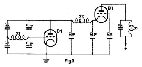
Figure 6. Principal circuit diagram of a cascode RF input amplififer. The relevant valve parasitic capacitances are also shown.
|
The basic characteristics of the dual triode cascode circuit is explained using Figure 6. S2 is the secondary winding of the input impedance matching transformer, where the 250-300Ohm antenna impedance is transformed upwards to the roughly 3kOhm input impedance of the first triode. Cag is the feedback capacitance from anode to grid of the triode, while Cgk is the input capacitance. By adding C3 and C7 of equal value as Cag and Cgk a Weatstone bridge is created that will prevent spurious oscillator signals to radiate out of the antenna. This is often referred to as neutralisation of the anode capacitance
One of the first main difference of the cascode to a standard triode or pentode input amplifier is the gain. The gain of a triode amplifier is gm*Rl, with gm the valve's transconductance in mA/V and Rl the load resistance. But because the first triode looks into the cathode of the 2nd (identical) triode, the load resistance of the first triode is the input resistance of the grounded-grid triode. Which is 1/gm ! This means that the voltage gain of the first triode is gm*1/gm=1. The main advantage of this is that the Miller-capacity, the virtual feedback capacity Cag(Miller) = (1+A)*Cag(intrinsic), is minimal and remains almost equal to the intrinsic Cag. This in turn guarantees a wideband input, covering the entire VHF-I and III bands.
One of the first main difference of the cascode to a standard triode or pentode input amplifier is the gain. The gain of a triode amplifier is gm*Rl, with gm the valve's transconductance in mA/V and Rl the load resistance. But because the first triode looks into the cathode of the 2nd (identical) triode, the load resistance of the first triode is the input resistance of the grounded-grid triode. Which is 1/gm ! This means that the voltage gain of the first triode is gm*1/gm=1. The main advantage of this is that the Miller-capacity, the virtual feedback capacity Cag(Miller) = (1+A)*Cag(intrinsic), is minimal and remains almost equal to the intrinsic Cag. This in turn guarantees a wideband input, covering the entire VHF-I and III bands.
The input signal of the 2nd triode Uk will be amplified - in-phase! - with gm*Rl, where Rl this time is the resonance resistance of the output bandpass filter S5-C4. The second triode thus provides the amplification. Noise of the 2nd triode appearing at its cathode will be voltage divided with the internal resistance of the first triode looking into the anode. This gives typically a 7 times reduction, which means that the equivalent noise contribution of the 2nd triode at the input of the first triode is only 15% of the total. The total Noise Figure of the PCC84 input stage came to 5-5,5dB, giving roughly halve the noise of the EF80 with its 8dB NF.
Finally, between the 1st and 2nd triode a resonant bandpass circuit is made using the inductor S10, which, in combination with the first triode output parasitic Cak and the 2nd triode input parasitic Cgk, resonates at the VHF-III band centre frequency around 195MHz. At VHF-I frequencies the inductance of S10 is reduced by a factor 4 and the circuit reduces to a low pass filter.
Finally, between the 1st and 2nd triode a resonant bandpass circuit is made using the inductor S10, which, in combination with the first triode output parasitic Cak and the 2nd triode input parasitic Cgk, resonates at the VHF-III band centre frequency around 195MHz. At VHF-I frequencies the inductance of S10 is reduced by a factor 4 and the circuit reduces to a low pass filter.
Tuner basics 4 - Automatic Gain Control (AGC)
|
Although the first generations of Philips TV sets (the TX380, TX390, TX400 and TX1410) did not feature Automatic Gain Control (AGC), it was introduced in the TX1720 from 1952 (commercially launched in 1953). AGC is a control loop, intended to provide a constant video output signal under all signal conditions. First order this means a constant output signal independent from the level of the input signal at the antenna. (AGC becomes more complex in case of strong unwanted channels, but we'll leave that out for the moment). Especially with the number of received channels increasing, the difference in signal strength between those channels could be considerable, with usually one very strong (from the closest transmitter) and others (very) weak, depending upon the distance of their respective transmitters. It was therefore no longer possible - like in the earlier sets that were designed to receive only one or very few channels - to set the gain of the RF-IF-video chain to a fixed value.
Most sets used a so-called delayed AGC, which worked as follows (I'll use the TX1720/TD1720 as a reference). The output of the video detector, so the negative modulation video signal, was fed to the cathode of a dedicated EF80 valve in a grounded grid configuration. The anode of this valve was pulsed by the blanking pulses coming from the line deflection unit, thus only gating the valve during these blanking pulses, which meant that the anode current became proportional to the black sync pulse level of the video signal. The anode voltage was divided down to a voltage between 0 and 5V, which was used to drive the grid voltage of the first three EF80 IF amplifiers. Because the cathode voltages were 5V, a grid voltage of 5V (and thus Vgk=0) would give maximum gain and amplification, Vg=0V and Vgk=-5V would cut the valve off. A second delayed control voltage was created through a resistive divider, and started to reduce when the first control voltage was already 2,5-3V lower. This control voltage was fed to the grid of the input triode. So overall when the received signal increased beyond a certain threshold, first the three IF amplifiers started to reduce their gain, while maintaining maximum tuner gain and thus lowest noise figure. Only when the input signal strength continued to increase the delayed tuner control voltage would kick in, now also reducing the pre-amplifier gain to avoid the RF mixer from overloading. At 5V control voltage all valves would effectively be cut off. Although actual voltages might differ depending upon the valves used, this principle of delayed AGC would be implemented in all TV sets from now on. It is now also clear why the 120Ohm cathode resistances were omitted from the real tuner design: as shown in Figure 8, the curve of configuration B without cathode resistors and using external grid biasing is much steeper, providing more amplification and thus lower noise. The behaviour of curve B is usually referred to as "sharp cut-off" as opposed to the "remote cut-off" of configuration A. The lower cut-off voltage (roughly -5V vs. -12V) provides easier AGC design and provides almost identical cut-off voltages for the PCC84 cascode and the EF80 IF amplifiers. Although all continental Philips TVs used the sharp cut-off and delayed AGC as described, it is said that Mullard preferred remote cut-off for its CCIR-A receivers. |

Figure 8. The Vg-Ia curves for two possible cascode configurations of the PCC84. Config.A obtaines the bias for the top triode through a 120Ohm cathode resistance, while Config.B uses external biasing of Vg2. The latter clearly has the steepest curve with the sharpest cut-off at around -5V. [Philips PCC84 Tube data]

Figure 9. The primary AGC voltage to the EF80 (U R ZF) and the delayed AGC to the tuner (U R KW) as a function of the voltage coming from the peak detector (Taströhre). [Valvo Kanalwähler, 1961]
|

igure 10. The complete RF-IF-video chain of the Philips TD1720 TV receiver, the first one implementing AGC. The red line is the primary AGC control signal to the three EF80 IF amplifiers, the green line is the delayed AGC to the tuner pre-amplifier. [Philips TD1720 Service Manual]
AT7530, introduction of the drum tuner, 1953
As mentioned, the AT5701 tuner family of 10-channel continuous capacitive tuning modules had some serious limitations, the most important of which was the bad noise performance due to the EF80 pentode pre-amplifier. But secondly tuning was always manual when the user changed channels, tuning through the entire band. Thirdly, but this is only an assumption, stability of the bandwidth characteristics must have been questionable given the continuous tuning of both the channel filter and the LO. Where these elements already demanded for a new tuner design, there was furthermore the need to shift the IF to the new higher values around 30-45MHz. All this resulted in the AT7530 family of tuners, that introduced quite a number of new features:
- the cascode input low noise amplifier, using the PCC84 dual triode optimized for RF performance
- the PCF80 mixer-oscillator, where the mixer pentode gives a higher isolation of the IF
- IF at higher, newly standardized frequencies in the 30-45MHz range
- different regional versions based on the same basic design, but aligned for the different standards
- the mechanical drum tuner concept, with up to 12 pre-set channels in the VHF-I and -III bands
- separate knob for fine tuning
- variable gain as part of an Automatic Gain Control loop
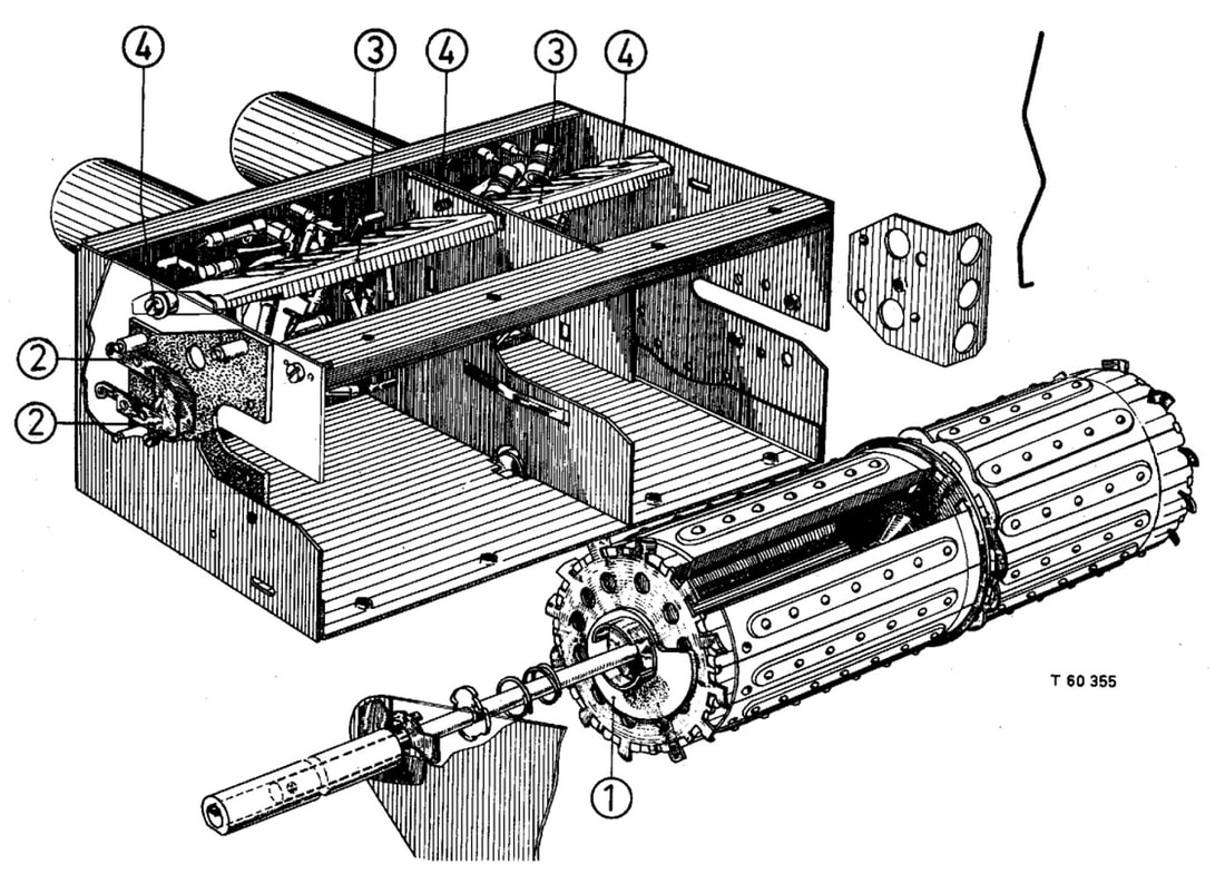
The principle of the drum tuner. On an axis two times 12 regularly spaced channel-specific filter modules are mounted. In front are twelve channel filter modules for both the channel filter and LO tank circuit tuning. Seven contacts are available, and one module is shown removed. The second row contains 12 modules with five contacts for the input filter circuit. In the tuner module the front section (for mixer-ocillator and channel filter) is separated by a metal shield from the rear RF input and pre-amp section. [Philips Service "Documentatie voor de kanalenkiezers met spoelenwals", 1954]
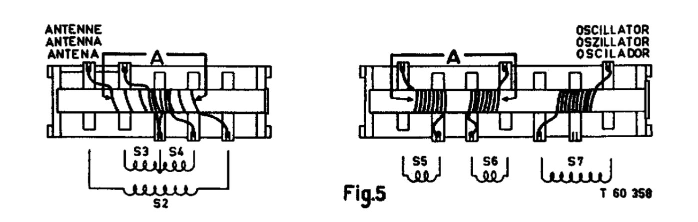
Examples of the "biscuit" filter modules as used in the drum tuner. Left the 5-contact input filter, right the 7-contact BPF and LO tank filters. In both modules the coils are co-axial for (maximum) mutual coupling.
|
The first, immediately visible innovation of the new generation tuners is the mechanics. The only similarity with the previous AT7501 is the square box, bot otherwise everything is new. A rotatable drum containing twelve pre-defined channel-specific filters determines the received channel, where the inductors of the input matching, the channel filter and the LO tank circuit are changed. The tuner is divided into two chambers for maximum isolation between the sensitive RF input and the mixer-oscillator-IF section with its much larger signals. Also on the drum there are two separate sub-modules, also referred to as "biscuits". The back of each inductor biscuit contains metal contacts (5 for the RF section, 7 for the LO-IF section) that contact a row of spring-based metal contacts (Nr.3 in the drawing on the left). With screws (4) the spring and contact force could be properly adjusted.
With this concept, which essentially turned the tuner module into a kind of Lego building block construction, many different tuners became possible. Depending upon the country of destination and its associated standard and IF settings, the required filter modules would be selected. Service workshops could later even add or exchange modules when new channels were introduced, since every inductor biscuit had its individual factory code and could be ordered separately. As a consequence more versions of the tuner were produced, covering at least standards B, B-for-Italy, C. E, F and M. |
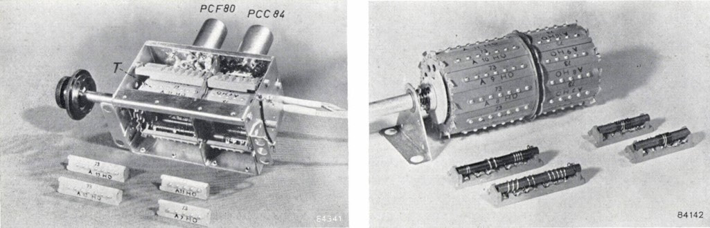
Detailed pictures of the new AT7530 drum tuner and its biscuits with the inductors for filter and LO tank frequency setting. [Philips Technical Review, Vol.17, No.6, pp. 161-188, 1955]
|
The second new valve introduced in the AT7530 family was the PCF80, a triode-pentode combo valve specifically designed for the VHF mixer-oscillator role. First order the circuit principles didn't change too much from the previous ECC81 based generation, with the triode acting as a Colpitts oscillator with a tuned feedback from anode to grid. The oscillator voltage was minimally 5V at the grid, and would be inductively coupled to the input of the mixer pentode. This inductive coupling was achieved by putting the oscillator coil S7 and the BPF coils S5 and S6 on the same rod inside the drum tuner filter modules, see Fig.5 above. By adjusting the distance between these coils for each channel filter module, the coupling constant could be kept more or less constant across all channels, providing as much as possible a frequency-independent mixer performance. For the mixer the pentode replaced the previous triode, providing more feedback isolation between anode and grid. All in all the new tuner must have given a considerable performance improvement compared to the previous generation.
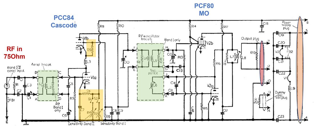
From the schematic it can be seen that the AGC voltage is connected directly to the cold side of the RF input, and through S2 DC-connected to the grid of the first triode. The secondary side of the interstage BPF was in turn connected to an external measurement pin on the exterior of the tuner metal can, which was used during factory alignment of the tuner. Finally, C18 was a variable capacitor parallel to the oscillator tank circuit, used for fine tuning of a channel. It was operated by pushing inwards and rotating the channel selector knob outer ring, that rotated the shaft of this capacitor. The IF output was tapped from the anode circuit of the PCF80 pentode through coupling transformer, thus making it galvanic isolated from the other tuner circuitry. |
The targeted pass band characteristics of the AT7530 tuner.
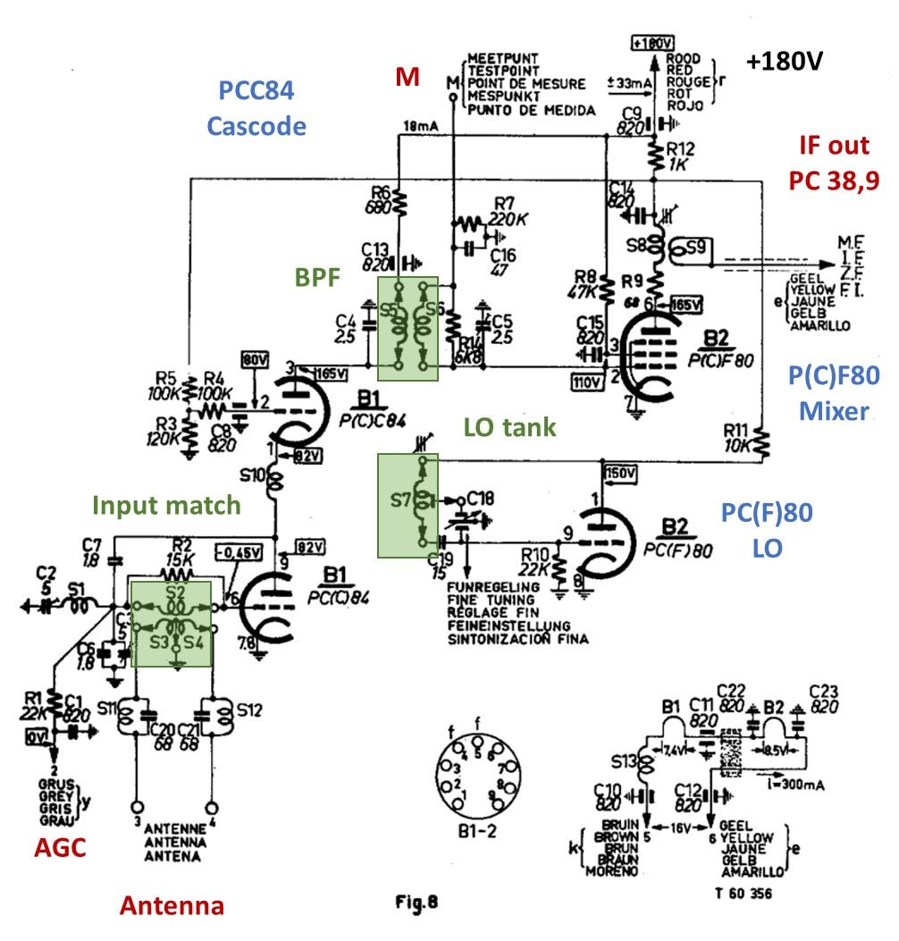
Circuit diagram of the Philips AT7530 12-channel VHF-I and III drum tuner, using the new PCC84 and PCF80 valves. The 5-6 coils in the green blocks are the channel-dependent inductors on the biscuit modules. This circuit diagram will be called "A" as reference for later modifications. [Philips Kanalenkiezers Service Manual]
|
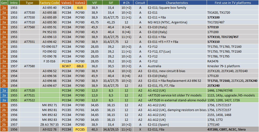
The known members of the Philips AT7530 tuner family, showing the different models with respect to covered channels and the IF standards. The models starting with A3 696 52 introduced a slightly modified electrical design, mainly related to biasing. A3 models are from Eindhoven, MK from Mitcham (UK), PK from Monza (It) and FD from Dreux (F). Non-standard valves are highlighted in yellow: 6U8=PCF80, 6CW7=ECC84, 6BL8=ECF80. In the last column bold text indicates Belgian multi-norm chassis versions.
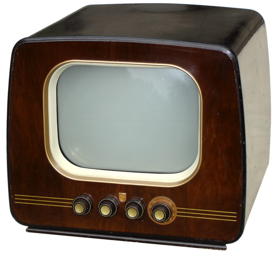
The first chassis to introduce the new drum tuner was the Philips TX1422, launched in 1953. [Marcels TV Museum]
|
The TX1422 family used a rather unique metal frame construction. Lower left the tuner is visible. [Marcels TV Museum]
|
The TX100 and TX110 chassis, launched in 1954, introduced the 4-norm receiver, a very successful concept. The additional norm switch knob is visible in the centre. [Marcels TV Museum]
|
The TD120 was a Krefeld chassis, which introduced the new "look" of the Philips TV as it would be dominant for the coming years. This is the 14TD120U Krefeld 3620 from 1954.
|
Interior view of the slightly bigger 17TD120U Krefeld 4320. Single chassis, on the right the HV cage, left the small signal section. The tuner block in front of or next to the chassis. [RadioMuseum.org]
|
Not a completely original version, but nevertheless interesting picture of the TX110 chassis in 2 parts, with left the small signal part and the AT7530 tuner block. [RadioMuseum.org]
|
|
This tuner family also introduced the first multi-norm tuners, for use in the 17TX100 and 17TX110 series for especially Belgium and French border zones. These tuners, like the AT7550, used the same picture IF of 38,9MHz as the regular CCIR-B versions, but required an extended channel bandwidth to accommodate the 13MHz channel bandwidth of the French 819-line standard. The sound carrier thus appeared at either 33,4 or 27,75MHz. With the drum tuner concept, using the optimized channel filter sub-modules, these type of customizations became a lot easier. The same method was applied for the NTSC and Italian standards, both using IF picture carriers around 46MHz, and Australian tuners with a lower picture carrier at 36MHz. Interestingly, in Australia, where the AT7580 was sold to the television manufacturer Kriesler, the tuner was modified to 6,3V parallel heater supply, using the 6CW7=ECC84 and 6BL8=ECF80 equivalents of the PCC84 and PCF80.
In 1954 the A3 696 52 introduced slight modifications in the biasing of especially the PCC84 triodes that would be carried over into the next generation (circuit A'). |
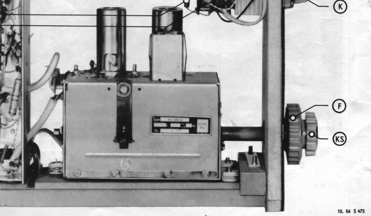
The A3 696 52 tuner mounted inside the 21TD140A, a Krefeld-produced German model. The right side is the front panel, with the two knobs KS (Kanalschalter, channel selecter) and F (Fine tuning). [Philips 21TD140A Service Manual]
|
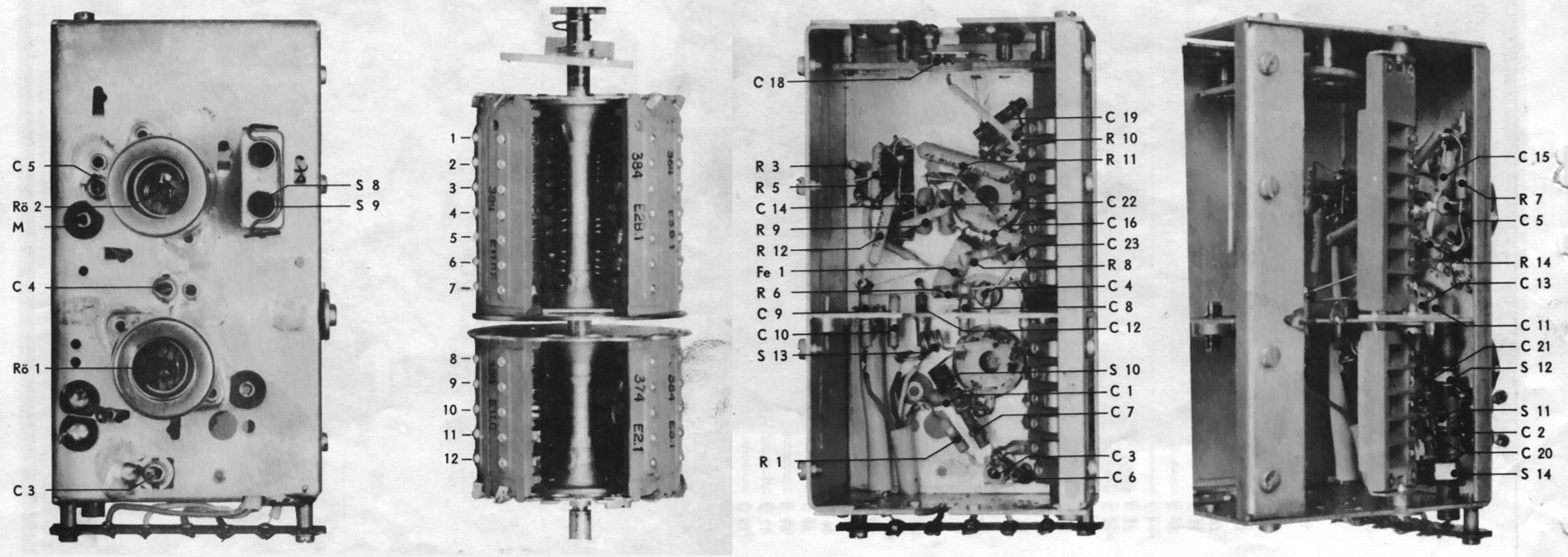
Four views of the A3 696 52 tuner. From left the top view; the drum with 10 channel filter modules mounted and two vacant; interior view from the bottom, with on the right the spring contacts for the drum (nrs 1-12 in the previous picture). At the top C18 is the fine tuning capacitor for the oscillator, which is operated by the outer ring of the control knob; a sideways interior view. [Philips 21TD140A Service Manual]
|
Within the AT7530 family the AT7520 UK version was the only one using a slightly different concept. As it seems this was driven by the specifics of the narrow band 405-line UK standard CCIR-A, with its positive picture modulation requiring different AGC control. At the same time these tuners were still 12MHz VIF - 8,5MHz SIF, since only the continental tuners had introduced the new high IF. The Mullard set designers apparently favoured a smoother and longer AGC control, using remote cut-off behaviour as per configuration A in Figure 8. The biasing of the upper cascode triode was thus different from the continental versions, connecting the grid to the cathode using an 18kOhm resistor.
In the UK, based on this tuner, four different RF solutions were available for TV sets when the new VHF-III transmissions were introduced in 1955:
|
Circuit diagram A2 of the Philips AT7521 and AT7522 UK tuners. Note that these were stil low-IF tuners, with a vision IF of 12,0MHz and the sound IF at 8,5MHz. In the yellow areas they differ fundamentally from the other tuners in the AT7530 family. The upper cascode triode biasing provides a remote cut-off characteristic, while these tuners did not feature AGC on the grid of the input triode, but manual gain setting in the cathode biasing. Green the biscuit circuits, red and orange the two connector plugs. [Trader Service Sheet 1232/T94 via Radiomuseum.org]
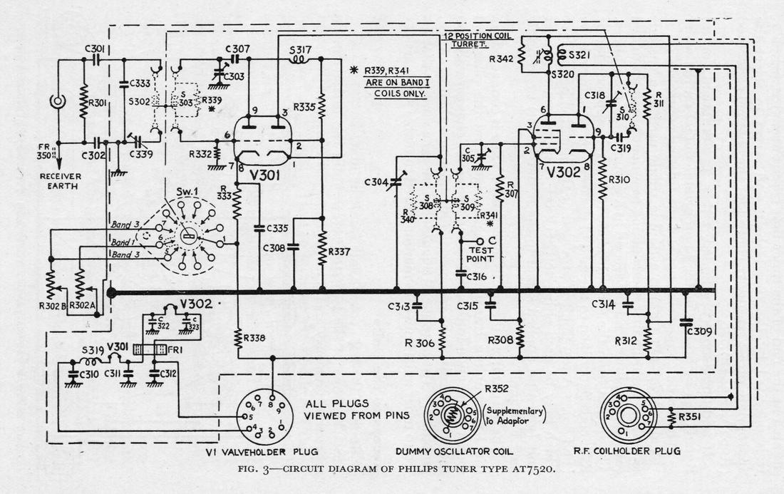
The same Philips AT7520 tuner as in the above picture, but now in its service upgrade configuration. Note the additional band selection switch (Sw1) which is connected to separate VHF-I and VHF-III gain setting potmeters. At he bottom of the picture the three plugs for insertion in the sockets on the RF-IF panel. [C.E. Lotcho, "TV Conversion for ITA", 1957]
|
For options 3 and 4 the tuners were equipped with two connectors that were compatible with the Noval sockets of the EF80's and coil filter modules of the original single-channel frontend. The 1st plug used the original EF80 pre-amp socket and connected the tuner to the 180V and heater supplies, the 2nd used the BPF coil socket and connected the IF output of the tuner to the chassis IF signal chain. A third plug contained a damping resistor for the now unused oscillator tank circuit coil. In the TV set the second MO EF80, which was left inside, now became an extra IF amplifier.
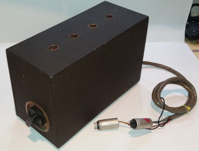
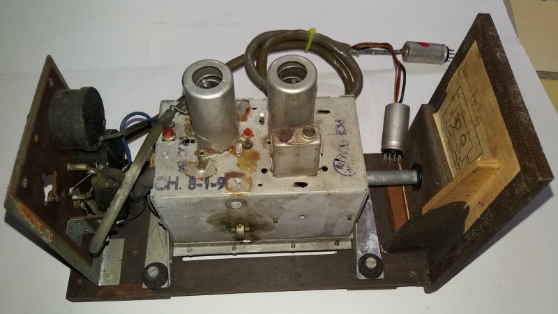
External and internal view of the AT7522 tuner add-on module for UK TV's. This version had channel 8, 1 and 9 filters built in. The two Noval connectors are clearly visible. [John "Heatercathodeshort" collection on UK Vintage Radio Forum]
|
|
|
Only in 1955 the TV tuner was consistently introduced in British sets, and no longer as an option. These tuners re-used the mechanics of the AT7520 and 30, but had on two aspects a quite different electrical design approach. The first was the biasing of the cascode. Where the Eindhoven design used classical resistor-based DC biasing of the upper triode grid to set all current s and voltages in the cascode, the Mullard design used a kind of floating biasing scheme. Here the cathode current of the upper triode through a 120 Ohm cathode resistor R3 sets the upper grid voltage through R2. The second difference is the rather unique balanced IF output, using a coupled transformer. This was already applied in the AT7522 above, possibly to provide better transfer characteristics of the fairly long IF output connection.
In parallel with the introduction of the tuner came an important concept change: the IF finally moved into the 30MHz range and became in line with the BREMA requirements: 34,65MHz picture carrier, 38,15MHz sound carrier. |
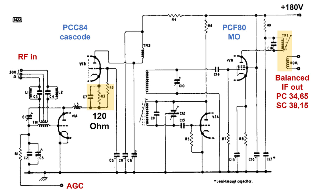
Circuit diagram of the Philips MK 892 xx tuner. Designed in Mitcham it was used in the first tuner-equipped TV sets in 1955. Yellow areas indicate where the design differed most from the Eindhoven reference.
|
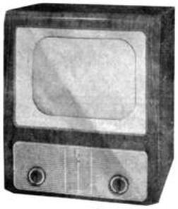
The 1955 series of British Philips TVs started to look fairly outdated. This is the 1758U. However, it was the first generation to have a rotary tuner mounted standard off-factory.
|
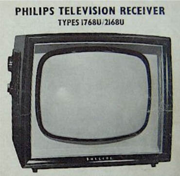
The 1956 Philips UK television sets 1768U and 2168U introduced a more modern look. Only the channel selection/fine-tuning and the co-axial volume & contrast control were on the left (!) side of the set, all other controls at the backside. [via RadioMuseum.org]
|
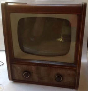
However, the 1957 1772U chassis again was a return to the already outdated 1955 look.
|
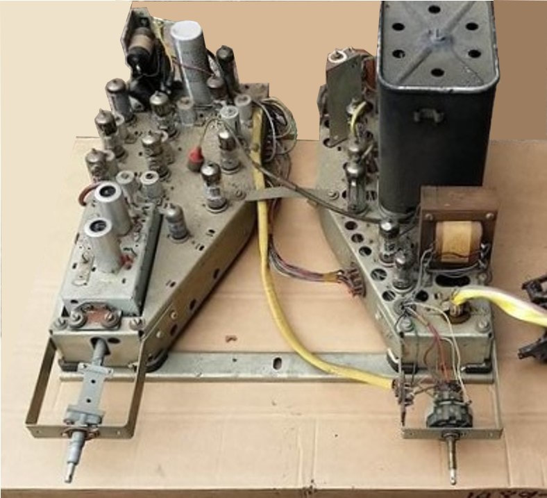
The 1458U and 1772U sets as shown above used a split, wedge-shaped chassis construction. Left the small-signal chassis, with the tuner module inserted into the chassis frame. [Radio TV UK Forum]
|
Rear interior view of the Philips 1768U. The different chassis design of Mitcham, as opposed to Eindhoven/Krefeld, is clearly visible. Note the old-style metal can for the HV supply. The MK 892 82 tuner is upper right, also a very unusual position. [RadioMuseum.org]
|
|
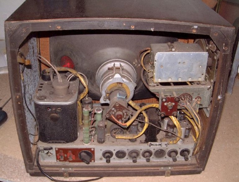
There is one more oddity, which I have conveniently put into this family, although strictly spoken it is not: the A9 022 78. To start, this is the only known tuner using the valve combination PCC84-PCC85. It is completely unclear why this design was used, other than a modest cost reduction compared to the PCF80. The circuit diagram was identical to the AT7530. However, there was one more odd characteristic: it used a VIF of 40,4MHz and a SIF of 34,8 (B/C/D) or 29,15MHz (F), values not seen in any other set. The reason for this is totally unclear, but probably related to the fact that this tuner was intended for third party set makers in Belgium CBRT (Brugge), ACEC (Charleroi) and Sierra. Possibly these were the IF values used by these set makers in their 4-norm televisions. The single Aristona model using this tuner was then probably an ODM model from CBRT. A9 was a Philips Service code, also indicating a different relation with the set maker than the internal fabs.
|
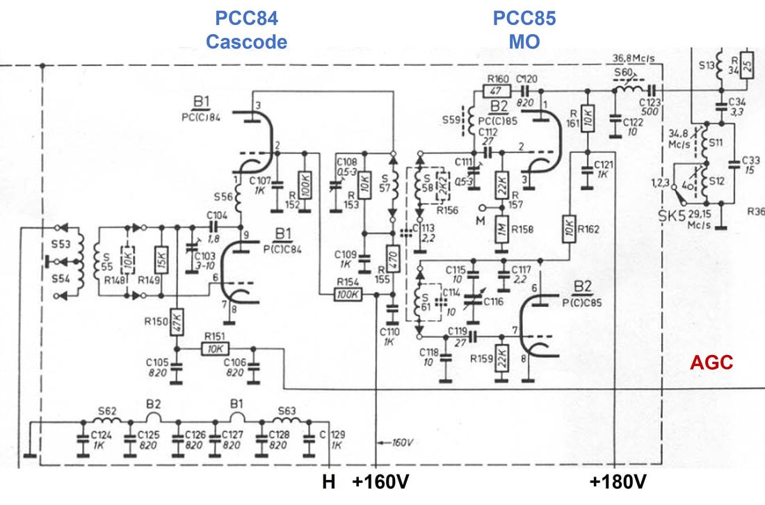
Circuit diagram of the Philips A9 022 78 tuner, with its unique PCC84-PCC85 valve combination. [Philips 43T200 Service Documentation]
|
Tuner Basics 5: French and Belgian multi-norm reception
The UK, being an island, could comfortably select a deviating TV standard, since there were simply no adjacent countries within reach with transmissions using different standards (we conveniently ignore the few thousand people along the Channel and on Guernsey and Jersey that could receive French channels). For France the situation was quite different, being surrounded by countries transmitting mostly CCIR-B signals (Germany, Switzerland, Italy and Spain). Neighbouring Belgium and Luxembourg had on the one hand made token compromises on their standards, but for all practical purposes these standards were still closer to CCIR-B than to the 819-line CCIR-E. In the broad swath of roughly 100km left and right of the French borders there was thus the need for multi-standard receivers and similarly along the Belgian borders. To complicate matters further, the French 819-line high-definition standard with 13,15MHz channel bandwidth used overlapping channels with inverted frequency arrangement; odd channels had a low picture carrier and higher sound carrier, the even channels high picture carrier and lower sound carrier.
To tackle these complexities essentially three tuner and IF arrangements have been used during the 1950-ies:
A. early French front ends and tuners using dual IF frequencies
B. French drum tuners with constant IF frequencies (but inverted compared to the standard tuners)
C. Belgian multi-norm tuners and IF
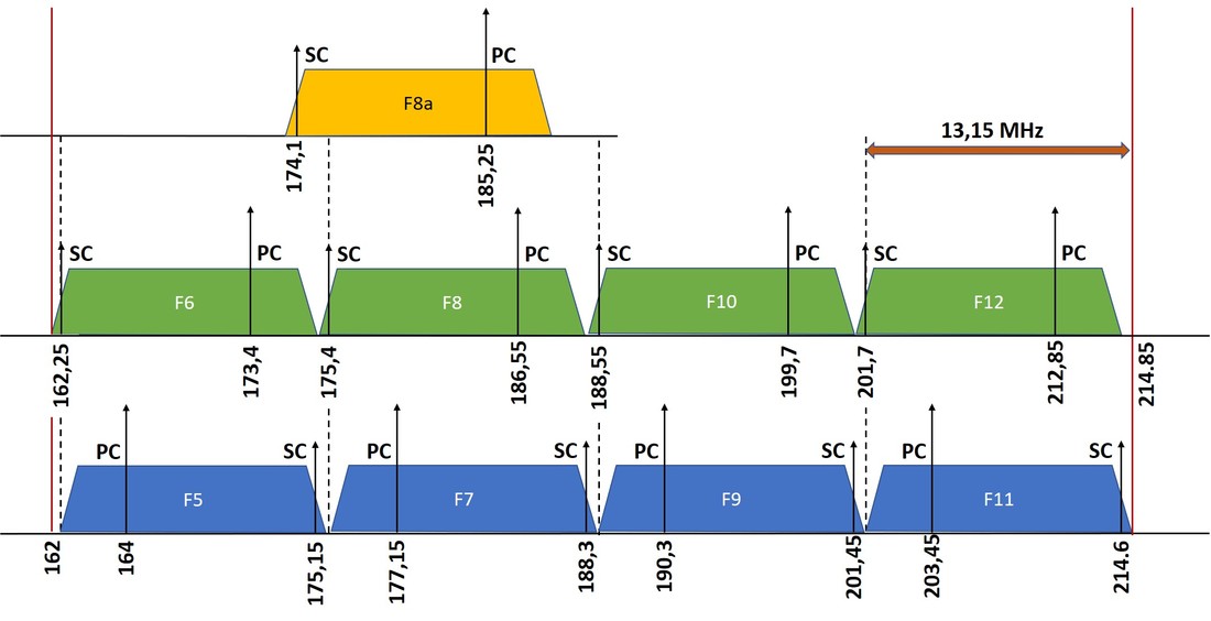
Figure 11. The French 819-line standard VHF-III channel allocation.
|
Before diving into the tuner specifics we need a quick look at the French channel arrangement, as shown left. To allow sufficient 13,15MHz wide channels in the VHF TV band the odd and even channels were inverted as shown, where the sound carrier frequencies of one set were located on the channel separation of the other set (see the dotted lines). Another oddity was channel 8A of the Paris and Lille transmitters. This channel was defined before the channel definitions were finalized and was shifted with respect to the standard channel raster. All in all a much more complex arrangement than the CCIR-A or -B standards.
|
|
The first generation ECC81 and PCC84 blocs monocanals and tuners consistently used the LO above the wanted channel. As a result an odd and even channel appeared inverted in the IF domain, see the example for odd channel F7 and even channel F8 in Figure 12. Note that the LO-frequency for channel F7 is identical to the picture carrier of channel F12, and the LO for channel 8 to the sound carrier of channel F11. This was done to avoid disturbing beats in case of interfering channels.
The consequence of this arrangement was that the sets required double-tuned IF chains, so 28,05 and 35,7MHz for the picture and 24,55 and 39,2 for the sound IF. For details on these sets see Piet's Home-built Television pt2. Also note that the total IF bandwidth was 15,15MHz, 2MHz wider than the channel bandwidth. This architecture was used in the TF1730 and TF1740 families. |
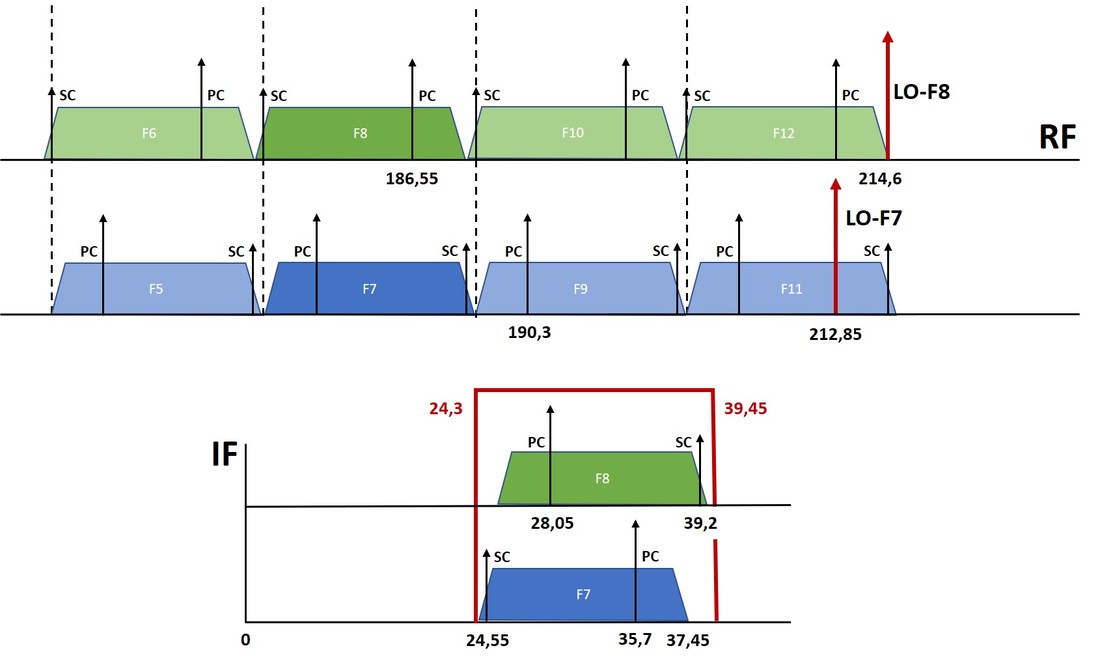
Figure 12. Tuner concept for the first generation French 819-line tuners, resulting in dual IF frequency television sets TF1420/1720, TF1730 and TF1740. Note that the LO for channel F8 has the same frequency as the sound carrier of channel F11, and similarly LO-F7 and PC-F12.
|
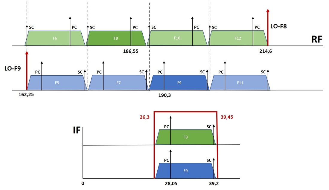
Figure 13. Tuner concept for the second generation French 819-line tuners, with fixed IF frequencies. This was introduced in 1955 with the TF1750 television set. Note that LO-F8 = SC-F11 and LO-F9 = SC-F6.
|
For the next generation French tuner and TVs a cheaper concept was chosen, starting with the FD 90 001 drum tuner, part of the AT7530 tuner family, and TF1750 set from 1955. For the odd channels now a low LO was used, resulting in identical video and sound IF carrier frequencies for all channels, see the example for channels F8 and F9 in Figure 13. In all cases the LO frequencies are identical to the opposite sound carriers.
The only difference with conventional CCIR-B tuners was the low picture carrier IF, an arrangement also used in British tuners. In both cases this was almost certainly chosen to avoid problems with interference from the lowest channel 1 picture carrier (in the French case F2 with picture carrier 41,25MHz). |
|
A third way of receiving French channels was used in the Philips 4-norm receivers for Belgium. As explained earlier, these sets were able to receive standard CCIR-B (Dutch or German channels), CCIR-C (Belgium Flanders, with AM sound), CCIR-F (Belgium Wallonie, 819 lines, 7MHz channel, AM sound) next to the standard French CCIR-E. Here Philips decided on a common video IF carrier of 38,9MHz, requiring another up-down inversion of the French channel LO frequencies. In the IF a switchable IF bandwidth was used between 7 and 8,5MHz. This meant that for the French signals some 2MHz of the upper video frequency range was sacrificed, which shouldn't have given any picture quality problems.
|
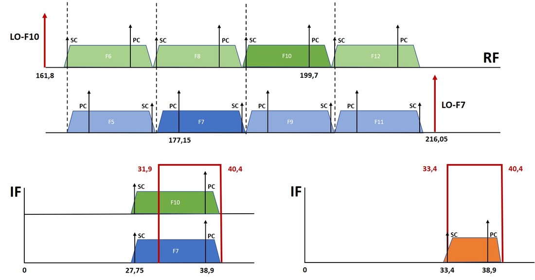
Figure 14. The tuner concept for French channels in the Philips multi-norm Belgian receivers. All standard used the same 38,9MHz video IF, with sound IF at either 33,4 (B-C-F) or 27,75 (France).
|
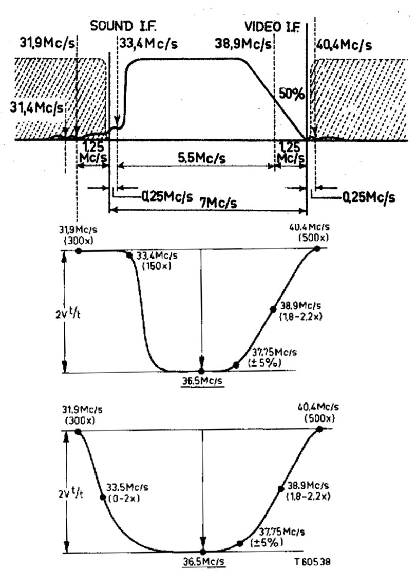
Figure 15. Video IF characteristics of Philips multi-norm receivers. From top to bottom the IF signal, the B/C/F video IF passband and below the system-E passband. [Philips 21TX170 service documentation]
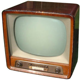
The multi-norm Philips 21TX170A. This chassis introduced the U-tube Noval range, like the UF80 and UCC85. [Marcels TV Museum]
|
In closing we'll have a last look at the IF of multi-norm receivers. Figure 15 shows the video (only!) IF characteristics. At the top the IF frequency characteristic of standard CCIR-B/C/F signals, where the only difference is the modulation format of the sound (AM or FM) or the line rate (625 vs 819 lines). In the video line up typically blocking filters are located at the adjacent N-1 sound carrier (40,4MHz) and N+1 picture carrier (31,9MHz). For the video (!) the sound carrier is of course also filtered out (at 33,4MHz) to avoid sound-to-video picture distortion. The result is the centre graph, showing the video IF passband in a Philips multi-norm receiver. For the French 819-line reception the video IF characteristics were essentially left unchanged except for the 33,4MHz filter that was removed because the sound was much lower at 27,75MHz. This resulted in the lower IF graph, with a -3dB bandwidth of roughly 5,5MHz, still substantially lower than the transmitted 10,5MHz video bandwidth.
Sound was treated differently. In the first 21TX100 and 21TX110 receivers the sound IF was separated from the video immediately at the output of the tuner, resulting in a dual frequency IF: either 33,4MHz (B/C/F) or 27,75MHz (E). These were down-converted a second time using an oscillator of 40,4MHz (B/C/F) or 20,75MHz (F), resulting in a 7MHz 2nd IF for further sound demodulation. From the TX170 the CCIR-B FM was using intercarrier sound at 5,5MHz which was used for FM demodulation, the AM sound being processed separately. This scheme was used well into the 1960-ies, when new methods emerged.
|
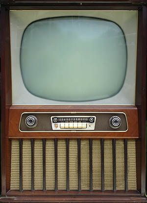
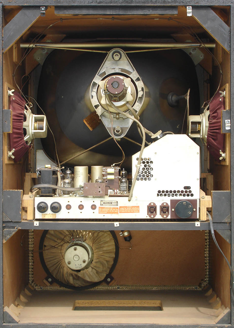
Philips 4-norm televisions, 1953-1961
From the very beginning Philips has put a very high priority on the Belgian 4-norm sets. Although they were primarily designed for the complicated Belgian situation with four standards (B/C/D/E), derived versions were needed on essentially all border areas of France: Germany and Spain (B/E) and Switzerland (B/E plus the Italian IF for B). Finding solutions for these areas, and being able to position Philips as the solution provider for all areas, was deemed extremely important. But such a solution was a challenge, which seems to have been given to the Natuurkundig Laboratorium Research organisation in Eindhoven, probably in close cooperation with the Apparaten-lab a few buildings down the road. This resulted in the TX100 chassis, which is described in detail earlier. It was together with the contemporary TX1420 and TX1720 the first chassis using the new AT7530 family of tuners. Philips was so proud of this solution that it appeared, together with the new tuner, in the prestigious Philips Technical Review magazine, albeit only in 1955. The different characteristics of the TX100 are summarized below.
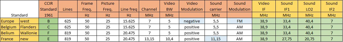
Overview of the standards by the 4-norm receivers for Belgium. The orange columns are the generic standard parameters, the yellow columns describe the Philips TX100 chassis solution.
After the success of the TX100 chassis, almost one in three chassis throughout the 1950s and early 1960s was a 4-norm solution, undoubtedly contributing to the broad acceptance of Philips as a leading set maker. The changes between these successive chassis were predominantly in two domains: the audio and efforts to automate the norm selection.
|
The TX170 introduced a new architecture for the sound. The Gerber-norm B FM sound IF was taken after the video detector as intercarrier sound, using two UF80 and PCF80 valves for amplification and three OA81 Germanium diodes for FM detection. The sound IF for the AM systems C/D/E was still taken directly at the the tuner output, amplified using three UF80 valves and then peak detected using two OA81 diodes. A norm-dependent switch then selected the detector outputs from either branch. The TX170 chassis was derived from the TX140, still suing the same frame mounted on a wooden carrier, and with the tuner in front of the chassis. It was followed by the TX220, TX230 and TX240 chassis in 1958-59, all still using the same internal chassis but equipped with the latest AT7632 tuner and a new cabinet style. The TX170-220-230-240 used 25 valves, the highest count for any of the 1950s Philips chassis, and an illustration of the complexity. And this was after further drastic measures, e.g replacing the four UY85 supply rectifier valves in the previous TX144 chassis by four AA250 Selenium power diodes, otherwise the count would have been 29 on a comparable basis. (From the TX220 chassis these bulky Se rectifiers were replaced by two OA210 Germanium power diodes).
|
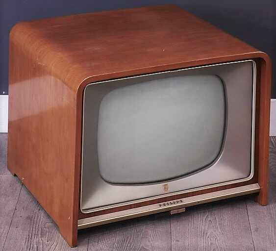
The TX220 multi-norm chassis introduced a new cabinet style, using more straight features. The interior chassis remained identical to the TX170. Here the 17TX220A.
|
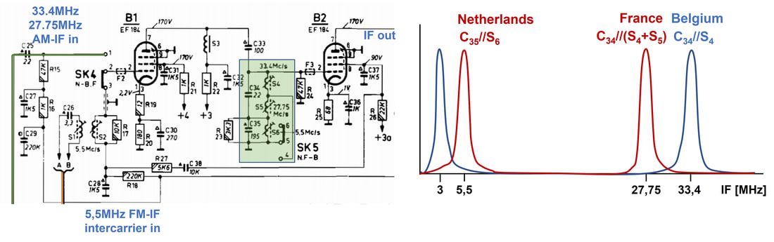
The new 4-norm sound IF arrangement in the Philips TX280 chassis. On the right the two integral transfer characteristics of the green BPF. Red is the situation for Netherlands-France N-F, blue for Belgium B. [Philips 21TX280A service Manual, 1959]
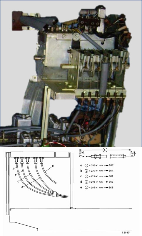
A rare but very nice look from the front side of the 21TX281 chassis, showing the multi-section norm switch mechanics and its outgoing six Bowden-cables to the electrical switches SK1-SK6. [Picture RadioMuseum.org]
|
The TX280, which appeared already the next year in 1959, saw another sound channel simplification. While still using 5,5MHz intercarrier for FM and 33,4 and 27,75MHz for the AM IF, these now shared the same IF amplifiers. A switchable BPF in the anode of the first IF amplifier was made of two stacked resonant circuits at 5,5MHz (for the intercarrier) and 27,75MHz (the French 819 lines IF). When receiving either of the two Belgian standards, part of the upper inductor was short-circuited to ground, shifting the resonant peak to the 33,4MHz IF. In the meantime the TX280 had moved to the same chassis architecture as the TX250, using a 110degrees CRT and the same frame layout. However, there was no room for the tuner, which was therefore placed higher up on a small platform. This platform also contained the new norm switch, now operated by a large knob on the side of the set. Six different rotary switch assemblies operated six Bowden-cables that ran to the different sub switches on the chassis. A third norm-related innovation was the automatic 625-819 line switching. A dedicated circuit around a PCF80 received the separated sync pulses from the regular synchronisation separator. These pulses are fed to a resonant circuit tuned to the 625-line 15.625kHz, and the output (negatively) peak detected. In case of a detected 15.625kHz signal the PCF80 triode is squeezed and the current through the relay blocked. For 819 lines the relay is active. The contacts operated by this relay were used inside the line and frame deflection branches.
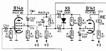
The automatic 625-line detection circuit, operatin gthe relay RE in the anode of B14t. [ibid]
|
|
The last step in these VHF-only 4-norm receivers was introduced with the TX300 chassis from 1961. Electrically everything remained identical to the TX280 as described. But the manual norm selection switch was now replaced by motor-control. To this end a standard setting rotating assembly was added, which - through Bowden cables - rotated synchronized with the VHF drum tuner. It also had twelve positions, and for each position (=channel) a notch could be set to N-B-F. These notches operated a three-position electrical switch, which in turn determined how far the motor-controlled norm switch would be rotated. Although this was a major ease-of-use improvement compared to the manual operation, the drawback remained that for each channel the norm had to be set at the back of the TV set.
All in all the 4-norm set remained a complex engineering challenge, but a continuing series of innovations made this a highly successful segment for Philips. |
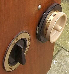
The 4-norm manual switch knob on the side of the TX280 chassis. This is the 21TX370 version from 1963. [Marcels TV Museum]
|
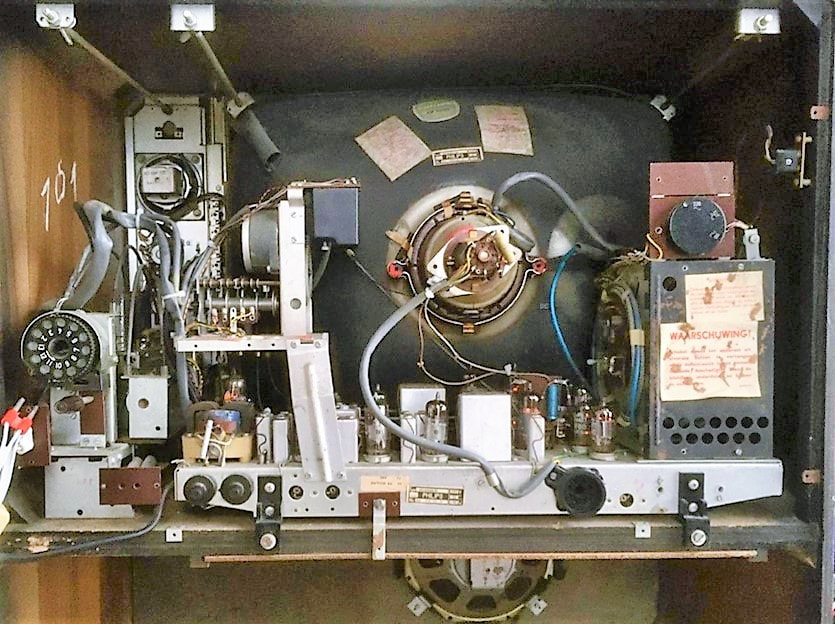
Full rear view of the 21CX302A console 4-norm TV with on the left the complex automatic norm-switching arrangement. [RadioMuseum.org]
|
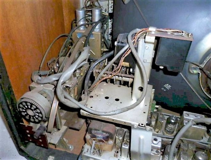
The automatic norm selection in the Philips 21CX302A. Lower left the 12-position norm setting wheel, synchronized to the VHF tuner in front through the two visible Bowden-cables. Upper right on the platform the black motor-control box and left of it the motor, that operated the attached 6-section rotary switch. [RadioMuseum.org]
|
The Philips Television organisation, 1950-1960
|
Throughout the 1950s television development and production within Philips remained part of the Hoofdindustriegroep (HIG, Main Industrial Group, in modern terms a Product Division) Apparaten (Devices). This was a large and continuously expanding HIG, covering Radio, Grammofoon (record players), white goods and of course television. For radio and television development there was the central Apparaten-lab in Eindhoven. Furthermore, Apparaten-specific complex components or modules were also part of the organisation, including loudspeakers, crystals, high-voltage transformers, inductor modules for RF and IF, and tuners.
Within the then operational Philips structure the country organisations were dominant, based on the approach that they could locally optimize sales of the Philips products. Most larger countries had established local production for the most successful products, like lamps and radios. Although the application organisation like Apparaten was expected to harmonize development of platforms and products across the countries for maximum efficiency, in practice this was difficult. Strong country managers established their own local development organisations next to the factories, stimulating local "country-optimized" development. So, when television emerged at the end of the 1930s, and after the interlude of WW2 again end of the 40s, the big countries each stimulated local television development. This was obviously strongest in countries that were ahead in television deployment compared to the Netherlands: Britain, France and to a lesser extent Italy. As described in the story on Piet's home-built television Eindhoven had a continuous struggle to have the Mullard-lab in the UK and the Suresnes/Dreux organisation in France aligned on the company television strategy and chassis development. This would last until the 1970s! However, there was one positive development supporting a more homogeneous and centralised approach: the establishment of the new 625-line "Gerber-norm" (later CCIR-B) across most of Western Europe (remember these were the Cold war years, and Eastern Europe obviously chose a difference standard, dictated by the Soviet Union). With Germany, Scandinavia, Netherlands and all of Southern Europe behind it, this created a large market. Chassis development for Gerber-norm sets was strongly centralised in Eindhoven, but local production was started in almost every country as soon as television sales picked up.
The exceptions were as mentioned the Mullard labs and Mitcham fab due to the British 405-line standard (CCIR-A) and Suresnes (Paris) in France due to the 819-line standard (CCIR-E). French production was initially in Suresnes. But however obstructive the UK and French National Organisations, both Britain and France were large markets for Philips, and in 1957 both countries received major new TV factories, in Croydon (Surrey) and Dreux (west of Paris). The third track was based on the Belgian/French/Swiss 4-norm (CCIR-B/C/E/F) solutions. These were developed in Eindhoven, as much as possible based on existing chassis, although they required substantial modifications. Apparently these multi-norm sets were considered very essential by the Apparaten-Television organisation, possibly to position Philips as the vendor able to solve the complex multi-norm solutions. During the 1950s almost half of the chassis developments were multi-norm! These were probably the last chassis being produced in Eindhoven, while the standard CCIR-B set production was increasingly moved to Krefeld. Later Philips started to use CBRT in Brugge (Belgium) as an outsourcing fab for 4-norm sets. |

The Philips mother TV factory in Eindhoven-Strijp.

The newly built Krefeld TV-fab.

The massive Philips Kopenhagen radio and TV-fab in Denmark, 1957.

Production carrier of a TX300 frame in the Monza TV-fab, early 1960s.

In Wien Philips/Hornyphon built a new fab for radio and TV production, Werk III.

The Philips Lamperas-Z factory in Barcelona.

n Australia Philips TV production started in the former Kriesler fab in Newtown, Sydney, until it burned down in 1960. [RMorg]

The Philips FAPESA TV-fab in Buenos Aires. [RMorg]
|

By 1956-57 three major TV production extensions were realized: a new fab in Dreux, France for the 819-line sets.
|
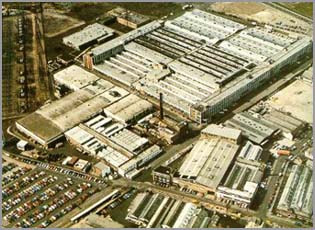
A new TV-factory in Croydon, Surrey, UK for the British 405-line sets.
|

A substantial share in the new CBRT TV factory in Brugge, Belgium for the Belgian 4-norm sets.
|

Overview of the Philips television factories during the 1950s and 1960s, the period of enormous growth and a TV-fab in almost every major country. The last column gives the letters as used in the type numbers of the tuners produced in each fab.
Philips TV set coding convention, 1955
Linked to the centralised Eindhoven development approach, also a single set type naming convention was defined and implemented from 1953. The general type number format was ssAB(C)xyz
Initially Mullard did not follow this new system, sticking to the old (local) convention of just a 4-digit number. Only by 1959, with the 17TG100 did they start the new system (but without following the central generation counter). France claimed exclusivity until well into the 1970s, using TF followed by 4 digits.
- First two digits ss: screen size in inches. 14-17-21-23" based on Philips CRT, occasionally third party CRTs were purchased for 24 and 27" screen sizes.
- First letter A: T=Television, C=Console, R=Radio-TV combo
- Second letter B (or BC if needed): Producing country, based on the same country-coding system as used for cars: A= Austria, CH= Switzerland, D= Germany, DK= Denmark, E= Spain, G= Great Britain, I= Italy, N= Norway, S= Sweden.
Non-European countries had different (less-obvious) codes: AL= Argentina, T= Australia
X= Netherlands - Third digit: Generation. This was definitely not linked to electrical design, but much more to external design of the set cabinet.
- Fourth digit: Chassis or family within a generation, simply in order of appearance
- Fifth digit: individual product identifier and luxury level indicator, where generally higher is more luxurious.
Initially Mullard did not follow this new system, sticking to the old (local) convention of just a 4-digit number. Only by 1959, with the 17TG100 did they start the new system (but without following the central generation counter). France claimed exclusivity until well into the 1970s, using TF followed by 4 digits.
The Radiobuizen-Lab or Dammers-Lab
|
Throughout the story up to now it is clear that tuner module development and key component (valve) development went hand in hand, because tuner performance was almost one-to-one related to valve characteristics. As we've already seen in the story on early TV development (here, here and here), the group responsible for (amongst others) the specification and development of new TV valves was the Radiobuizen-Lab (Radio Valve Lab) located initially on the 4th floor of the Witte Dame building (EF4) along the Emmasingel in central Eindhoven. The group responsible for Consumer Valves, serving radio and TV applications, was led by Bert Dammers, the boss of my father when working there, and as explained earlier a brilliant designer of innovative valve-circuit combinations. He was personally at the basis of the success of the Philips television, radio valves and even the tuner businesses. As a consequence of the broader television growth, both in sets and components, also the RBL Consumer Group continued to grow, led by Dammers. In 1956 he became the head of the entire lab, covering both Consumer and Professional groups, and the lab was subsequently usually referred to as the "Dammers-Lab". In the meantime it moved to the first floor (EF1) in the Witte Dame.
|

Bert Dammers (1910, 1968), the brilliant head of the RBL and later CAB. [Dos4Ever]
|

Some impressions from the Radiobuizen-lab in the early 1950s, when located on the first floor at the Emmasingel. Note that a real engineer at the time wore a tie! In the bottom-right picture two of the large valve characterization set-ups are visible, with their array of voltage and current measuring displays. [Via Ronald Dekker, Dos4Ever]
|
During the early 1950s the RBL Consumer Group was undoubtedly occupied with the improvement of the many TV functions, driving for more advanced valves that would either reduce cost (often by integrating functions into combi-valves like triode-pentodes) or increase performance (e.g. the series of improved power pentodes like the EL86 for audio and the PL84 for the line output). Frame grid valve developments will definitely have been part of the activities, leading to the improved RF valves used in the tuners.
The RBL essentially continued its activities unchanged from the time it started in 1946, growing with the business of the HIG Elektronenbuizen. Only in 1965, so after almost twenty years, there was a real change: the HIGs Elektronenbuizen and Industrial Components (ICOMA) were combined into the new HIG Electronic Components and Materials (ELCOMA), and the Radiobuizen-Lab was re-named Centraal Applicatie-Laboratorium Bouwlelementen (Central Application Lab for Components, in short CAB). This was also the trigger for moving the lab out of the Emmasingel to the Beatrix complex on the western outskirts of Eindhoven, which was implemented in 1967. However, Bert Dammers didn't witness this any more, since he fell seriously ill and died January 1968 at the young age of 57. The Lab would nevertheless continue to play an important role in component innovation as we will see in the coming chapters. |
PCC88 the first frame grid valve, 1956
In 1956 an upgrade of the AT7530 family was introduced, using a next generation RF valve: the PCC88. This valve was another Eindhoven Radiobuizen Lab development within the HIG Elektronenbuizen (Electron Valves Division), undoubtedly driven by requests from the HIG Apparaten (Set Division) for improved tuner performance. As was mostly the case with new valves, the first version was a 6,3V parallel heater version ECC88, followed shortly by the 300mA serial heater PCC88 version. (It would also be produced extensively as the E88CC high quality professional version as well as the 6DJ8 in the US). The PCC88 was introduced in Philips sets in 1956, although it seems the commercial launch to third parties was at least one year later. Apparently Philips wanted to keep the new valve away from competition.

Pictures of a classical (PCC84, top) self-carrying grid and a frame grid (PCC88, centre). The scale indicates 1 inch. The windings on the frame grid are so thin that they are hardly visible on this bad quality picture. [Mullard brochure Frame Grid Valves and how they work, in Wireless and Electrical Trader, October 1960]
|

n frame grid valves the nominal cathode-anode distance (x') could be reduced because of the receded anode. Compared to the classical anode (dotted in above picture) both the mechanical alignment tolerances (y-y') and the parasitic capacitances have been reduced. Nominal distance x' was 57um. [Mullard Outlook Australian Edition Vol2, No.6, 1959]
|

Cross section of the Philips PCC88 RF double triode, showing the two frame grid sections, the specially folded anodes and the central screen. [Mullard Outlook Australian Edition Vol2, No.6, 1959]
|
The PCC88 was one of the very first valves to be based on the "frame grid" technology (in Dutch spanrooster and sometimes also called "guided grid"), a breakthrough that delivered almost twice higher transconductance and thus amplification. The basic concept was to bring the first grid as close as possible to the cathode, while simultaneously increasing the number of windings of much thinner wire (from 75 or 50um to now 10um). To provide structural strength and stability the grid windings were wound on a pre-fabricated molybdenum support frame. To make the distance between cathode and grid constant, the cathode emitting materials were no longer sputtered onto the cathode metal frame but laid around it like a ribbon. The distance between cathode and grid could thus be reduced to 50um. As a result of this the anode could now also be brought much closer to the grid, at least in the flat area between the support rods of the grid. The net effect of these measures was a doubled transconductance (from typically 7 to 14-15mA/V) at roughly constant parasitic capacitances.
|
Interestingly the PCC88 did not achieve better RF performance by making it e.g. smaller and reducing parasitics, but instead it became slightly more robust to accommodate higher currents, thus achieving a substantially higher transconductance gm. At 90V Vak and zero Volt grid voltage the anode current Ia went up from 23mA (PCC84) to 35mA (PCC88). At the same time the parasitics increased somewhat: the critical feedback capacitance Cag from 1,2pF to 1,4pF, the input capacitance Cgk from 2,3 to 3,3pF. I assume that the reasoning has been:
a. the slightly higher input capacitance can be tuned out with the input matching circuit, worst case giving a slightly lower quality factor Qin, but this won't degrade the overall input performance b. the higher gain, specifically in the top triode, will provide for a larger RF input at the mixer, thus reducing the noise contribution of the mixer pentode. Overall this must have provided for a sufficiently important (noise figure) improvement to justify the introduction of a dedicated new valve. Which seems to have been successful in this respect, since it would be the standard pre-amplifier valve in Philips tuners for almost eight years, from 1956 to 1963. One further modification compared to the PCC84 was the screen separating the two triodes. In the PCC84 this was connected to the grid of the second triode for (RF) grounding. The 9th pin (next to the 2x three for the triodes plus two for the heater wires) was used to provide a second cathode contact of the bottom triode cathode. In the PCC88 this cathode contact was sacrificed to provide a separate pin for the screen, which could now e.g. be really grounded, as opposed to the 2nd grid that was only RF-grounded through a capacitor. 
Basic information about the PCC88 including the main parasitics. Data set 1) is without a metal screen across the valve, 2) with a screen. Not surprisingly this screen mainly influences the parasitics of the most outward anode. [Philips PCC88 Valve Information Sheet]
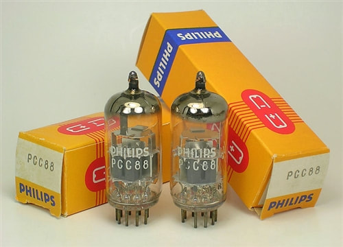
The PCC8 dual triode. Later they were also offered as matched pairs, with identical characteristics.
|
Philips Tuner naming and codingIn contrast to e.g. radios and television sets that had a well-defined, albeit regularly modified, naming convention, the tuner was one of the many components and modules that went into a set, and therefore followed different coding schemes. During the 1950-ies up to 1963 there were two categories of codes attached to modules like a tuner: factory code and possibly a product code.
Factory Code All components that went into a Philips set, from the smallest resistor and screw to a complete tuner module, were allocated a factory code. For Eindhoven-designed television sets these codes mostly started with A3 followed by three digits indicating the component category and two digits for individual parts. For tuners the category code started with 694, then 695 and 696. However, towards the end of the decade this system became congested, and we will start seeing jumps to free numbers. At a certain moment modules were also produced in other locations, Krefeld (BRD), Monza (It), Mitcham (UK) and Dreux (F) being examples. In that case components obtained a local factory code according the same principle but with A3 replaced by mostly a 2-digit code. Krefeld was KR, Monza PK, Suresnes or Rambouillet FK, Dreux FD, Mitcham MK. Barcelona, in contrast, put ZB in front of the A3-code. Product name A (tuner) module only received a formal name code in case it was also delivered to external customers. There were a number of components grouped into categories like: AC = Crystals, (Electrolithic) Capacitors AD = Speakers and transformers AP = HF and IF coils AR = (variable) Resistors AT = Television-specific modules; Tuners, Line Output Transformers & Deflection Coils, Remote Controls. (Sometimes it's said that AT was "Afstemeenheden en Transformatoren" (Tuning Devices and Tranformers), but this was not the official source of the code). So the T stands for Television, and not for Tuner! Within the AT category VHF tuners were coded AT75xx, UHF tuners AT63yy. Later also the category NT57xx was used for tuners, but it is unclear where this came from. Production code Finally it should be noted that actual modules received a tracing code referring to the production plant. Especially Eindhoven used internal Philips sub-contracting for its manufacturing, e.g. to the Volt factory in Tilburg. Products in that case received the code V followed by 2 digits for the week code and one digit for the year (1953 = 3 etc.). So V273 for week 27 in 1953. [Most of these backgrounds are from Maarten Bakker, an expert on Philips product and component coding schemes.] |
KR 361 52 family with the PCC88, 1956
In principle the new PCC88-based tuner had the same circuit diagram as the previous AT7530 generation, including the slight biasing modifications of the upper cascode triode (the two resistors forming the voltage divider for the grid voltage were increased from 10ok and 120kOhm to 820k and 1MOhm, possibly to provide higher isolation of the oscillator signal through the power supply lines). To allow a "deeper" gain control of the input triode, the main change in the design was the introduction of a series cathode resistor of the input triode, R4 of 120 Ohm and RF decoupled by C11 of 820pF. This put the cathode DC voltage to almost 3V at Vgk=0V. Finally as can be seen on the circuit diagram, the now separate screen of the PCC88 was directly grounded to earth, while an RF bead was introduced in the anode feedback capacitor C7 to avoid oscillations. The oscillator and mixer circuits around the PCF80 remained unchanged, including the galvanic output coupling.
The first known tuner-specific publication by Philips, in this case a September 1958 Philips Service booklet on the A3 768 xx tuner family, containing circuit diagram and alignment instructions. [Ite Weide]
With the growth of the television business also tuner production spread towards the different television factories. The latest PCC88 family saw the introduction of tuners from Krefeld (Germany) and Monza (Italy). At least in the case of Krefeld the tuners were not straightforward copies of the Eindhoven tuners (coded A3 768 xx) but introduced some design modifications:
|
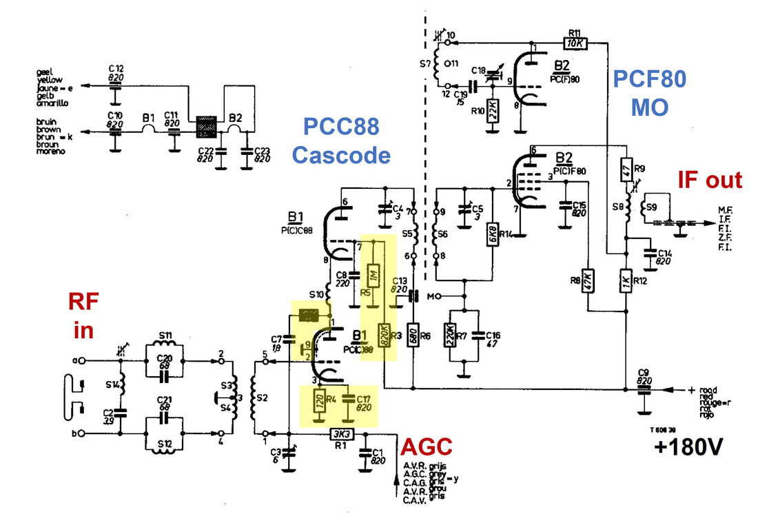
Circuit diagram of the Philips A3 768 xx 12-channel drum tuner, introducing the PCC88 RF triode. This circuit will be referred to as "Circuit B". Circuit changes compared to "A" are highlighted. The dotted line has been added for clarity, representing the magnetic coupling between the S5-S6 BPF and S7 oscillator tank circuit, which is responsible for the oscillator voltage injection into the PCF80 mixer pentode grid. [Philips A3 768 24 Service Manual]
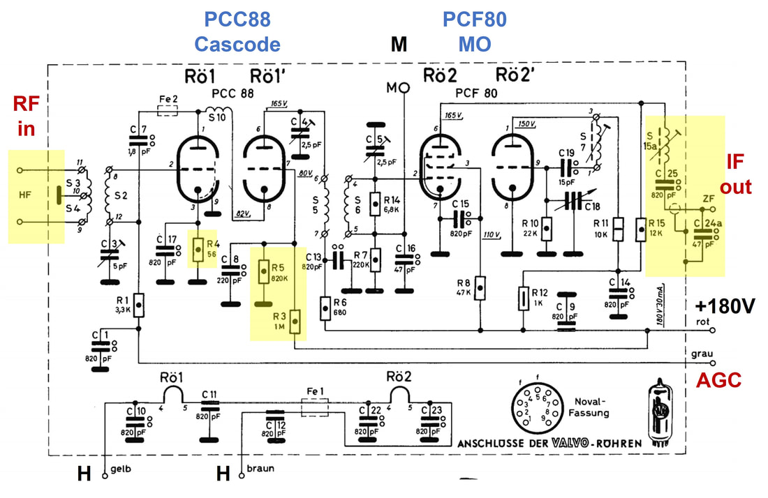
Circuit diagram of the Philips KR 361 52 12-channel drum tuner. This circuit will be referred to as "Circuit C1". The circuit areas highlighted in yellow are the small changes compared to "B", that were introduced with the Eindhoven A3 768 15. [Philips KR361 54 tuner Service Manual]

The Philips A3 768 28 tuner, which used the PCC88. This was a version for Belgium, covering the four norms. [Philips Service Manual]
|
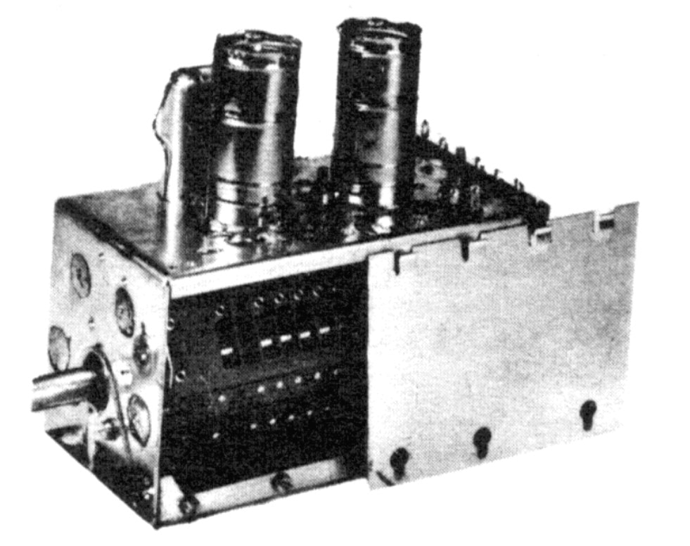
The Philips KR 361 54 tuner, the first one introducing Automatic Frequency Control using an OA70 germanium diode. [Philips Service Manual]
|
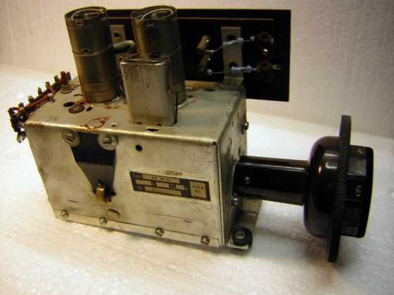
The A3 768 44 with the antenna connector panel mounted to its side. [Radiomuseum.org]
|
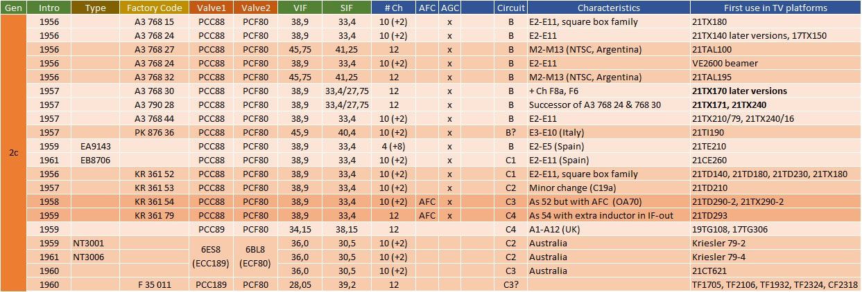
Overview of the known models of the A3 768 15 Philips tuner family, the first to introduce the PCC88 valve. These tuners still used the first generation rectangular box containing the drum mechanism. A3 are Netherlands models, KR are from Krefeld (BRD), FR from Dreux (France) and PK from Monza (It). The EA9143 was produced by the Z-factory in Barcelona (Spain), a Philips subsidiary. TV product codes in the last column in bold indicate 4-norm sets for Belgium, France and Switserland. Especially in remote countries like Australia the change-over between generations was different, using later valves in combination with the old mechanics.
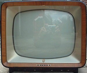
The TX180, 190 and 210 families were based on the same basic 19-valve chassis. The base models introduced the very convenient control knobs below the screen. This is the 17TX180U from 1956. [Marcels TV Museum]
|
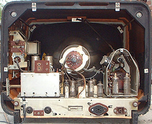
Interior view of the Philips 21TX180U. To make the sets more compact the tuner module moved on top of the chassis, left. It also introduced a new HV cage, on the right. [ibid]
|
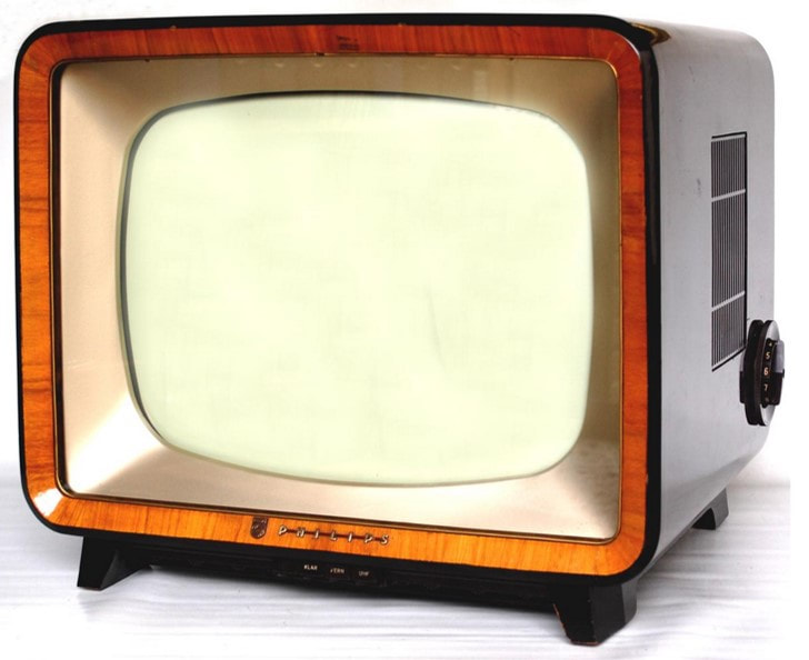
A Krefeld version of the 180 chassis, the 17TX210A. The 190 and 210 families featured, versus the 180 base model, also push buttons on the front side. [RadioMuseum.org]
|
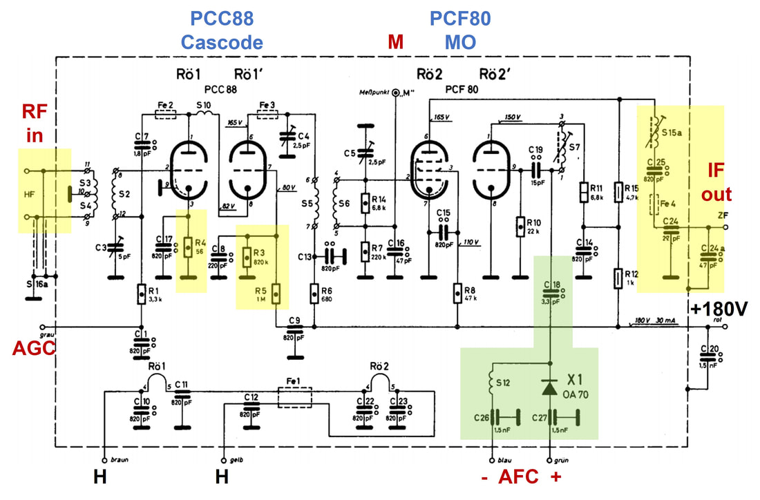
The Philips Krefeld KR 362 54 tuner, the first to introduce AFC. Yellow refers to the C1 circuit modifications, the green area to C3. The series capacitance of C18 and the diode X1 form a variable capacitance parallel to the LO tank tuning inductor S7. [Philips KR 362 54 Service Manual]
The user control for the AFC on the 21TD251A: the third push buttom from the right marked "Autom" (the equivalent of AFA on the Dutch TX251A) switches off the AFC, in which case the frequency can be controlled using the horizontal vernier wheel at the bottom (potmeter F in the circuit diagram). [RadioMuseum.org]
|
However interesting the AFC concept, it was not to become a standard feature in the Philips TV's. Apart from the few 21TX250 and 23TD290 versions, both from 1958 in the Netherlands and Germany, respectively, there are no traces of AFC in subsequent platforms. The reason for this is not clear, but can be related to for example cost, stability of the solution or the lack of visible added value. Or, phrased more positively, the integral frequency stability of the Philips TV receivers was apparently such that no AFC was required!
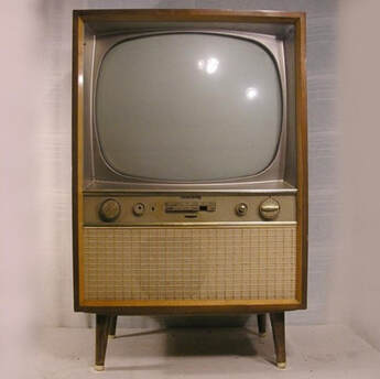
One of the very first Philips sets with AFC: the 21CX252A. Although this was obviously an above-standard set, it was not the most luxury TV family at the time, that was the 290. [RadioMuseum.org]
|
Tuner basics 6: Automatic Frequency Control (AFC)
Automatic Frequency Control (AFC) is a control mechanism where the frequency of a signal is kept at a constant frequency. In practice this means that the frequency of an oscillator is controlled although the frequency that is being measured and thus controlled is not necessarily the oscillator frequency proper. In TV reception the purpose of the AFC is to control the IF stability, where the control mechanism is to tune the tuner RF oscillator. To this end the AFC will have to measure the deviation of the signal frequency from a desired value, thus requiring a zero-crossing frequency discriminator, where the error signal due to a possible instantaneous deviation from this target frequency would drive the oscillator in the right direction to bring the difference back to zero.
AFC was an expensive function, requiring a dedicated PCF80, and was only used on a limited number of high end sets. The first use was in the 21TX251A, an Eindhoven design using the next generation A3 792 41 tuner, and the 21TD290A, a Krefeld-designed version using the KR 361 54. Both tuners are from 1958, while the sets were launched in 1959/60. Because the 21TX250 design is simpler (since only for VHF reception) than the 21TD290 (which also featured a UHF tuner with the associated switching) we will use here the first schematic to analyse the AFC. For the AFC the IF signal was taken from the last IF amplifier output, just before the video detector, and fed (the green line) to the pentode of the PCF80 (B25p in below schematic) for buffering and amplification. A Foster Seeley discriminator using two OA72's then provided a frequency discriminator curve centred at 38,9MHz, the picture carrier. The triode section (B25t) essentially buffered the discriminator output ( a voltage proportional to the deviation of the picture carrier from 38,9MHz) and generates a control voltage for the tuner (red and purple lines).
AFC was an expensive function, requiring a dedicated PCF80, and was only used on a limited number of high end sets. The first use was in the 21TX251A, an Eindhoven design using the next generation A3 792 41 tuner, and the 21TD290A, a Krefeld-designed version using the KR 361 54. Both tuners are from 1958, while the sets were launched in 1959/60. Because the 21TX250 design is simpler (since only for VHF reception) than the 21TD290 (which also featured a UHF tuner with the associated switching) we will use here the first schematic to analyse the AFC. For the AFC the IF signal was taken from the last IF amplifier output, just before the video detector, and fed (the green line) to the pentode of the PCF80 (B25p in below schematic) for buffering and amplification. A Foster Seeley discriminator using two OA72's then provided a frequency discriminator curve centred at 38,9MHz, the picture carrier. The triode section (B25t) essentially buffered the discriminator output ( a voltage proportional to the deviation of the picture carrier from 38,9MHz) and generates a control voltage for the tuner (red and purple lines).

Figure 17. Tuner, IF and AFC circuitry of the Philips 21CX252A television. The green line w is the input to the AFC circuit, the red and purple lines y and z are the output to the tuner module. AFA is the Automatische Frequentie Afregeling (AFC) selector between AFC (position as shown) and manual. In case of weak signal reception the AFC can be disabled with switch AFA, allowing manual fine tuning using the potentiometer F (R241) to shift the picture carrier up on the Nyquist slope. Potentiometer IA (R253) is for the factory null setting of the AFC. Note that on this TV the AGC (lines g to the EF85 and x to the tuner) only operates on one IF stage plus the RF input. [Philips 21CX252A Service Manual]
|
The control voltage across the diode inside the tuner (red and purple lines) induces a forward current through the AFC diode. The current through the diode will result in a changing parasitic capacitance that will de-tune the oscillator tank circuit in the right direction. Note that the AFC is thus based on the forward effective capacitance change of the diode, which is not the same as the reverse capacitance of a variable capacitor (Varicap) diode, introduced later! The fine tuning concept is also known as Stromflusswinkel-steuerung (conduction angle control) because what is effectively controlled is the duration of the conductive state of the diode in each RF signal cycle, see figure 16. Depending upon the bias voltage (Richtspannung in the illustration) the diode conducts during an angle alpha relative to 360 degrees of a full RF signal cycle. This in turn gives a varying effective resistance of the diode, which - in combination with the coupling capacitors - yields a variable equivalent parallel capacitance.
|

Figure 16. The principle of Stromflusswinkelsteuerung or Conduction Angle Control. Depending on the control voltage the time the diode conducts during a signal cycle varies, expressed by the effective conduction angle alpha. This results in a changing effective capacitance of the diode parallel to the tank circuit. [Heinrich Bender, Der Fernseh Kanalwähler, 1964, p.95]
|
|
The Philips Krefeld KR 362 54 tuner, the first to introduce AFC. Yellow refers to the C1 circuit modifications, the green area to C3. The series capacitance of C18 and the diode X1 form a variable capacitance parallel to the LO tank tuning inductor S7. [Philips KR 362 54 Service Manual]

The user control for the AFC on the 21TD251A: the third push buttom from the right marked "Autom" (the equivalent of AFA on the Dutch TX251A) switches off the AFC, in which case the frequency can be controlled using the horizontal vernier wheel at the bottom (potmeter F in the circuit diagram). [RadioMuseum.org]
|
However interesting the AFC concept, it was not to become a standard feature in the Philips TV's. Apart from the few 21TX250 and 23TD290 versions, both from 1958 in the Netherlands and Germany, respectively, there are no traces of AFC in subsequent platforms. The reason for this is not clear, but can be related to for example cost, stability of the solution or the lack of visible added value. Or, phrased more positively, the integral frequency stability of the Philips TV receivers was apparently such that no AFC was required!

One of the very first Philips sets with AFC: the 21CX252A. Although this was obviously an above-standard set, it was not the most luxury TV family at the time, that was the 290. [RadioMuseum.org]
|
AT7630, new mechanics, 1958
In 1958, more or less in parallel with the introduction of UHF tuners, the VHF tuner underwent some changes, introduced as the AT7630 family. In contrast to earlier innovations these changes were pre-dominantly mechanical:
- a new module housing, with the bottom sides slanted inwards, roughly following the contours of the revolving drum inside. This was undoubtedly a materials saving measure, since the two lower areas of the tuner were unused. This basic form factor was to have a long life, even surviving the introduction of transistors and only to be replaced in the early 1970-ies.
- printed coils on the channel-specific "biscuits" used in the revolving drum. This was again a cost saving, avoiding the costly manual labour of assembling the many different precision air coil assemblies. Challenges with the new concept were most probably the accurate trial-and-error definition of the proper inductive values of the printed coils, the lower Q (quality factor) of printed inductors versus air coils, and space. Especially for the low frequency coils the challenge was undoubtedly to obtain sufficient inductance with as many as possible windings on the limited available area of the biscuits printed circuit board (PCB). Also, compared to the standard PCB technology introduced for the main electronic board in TV's, these tuner biscuits required substantially finer traces and thus a more accurate printing and etching technology.
- Memomatic, an innovative mechanical construction to store the fine tuning setting for each of the 12 channels individually.
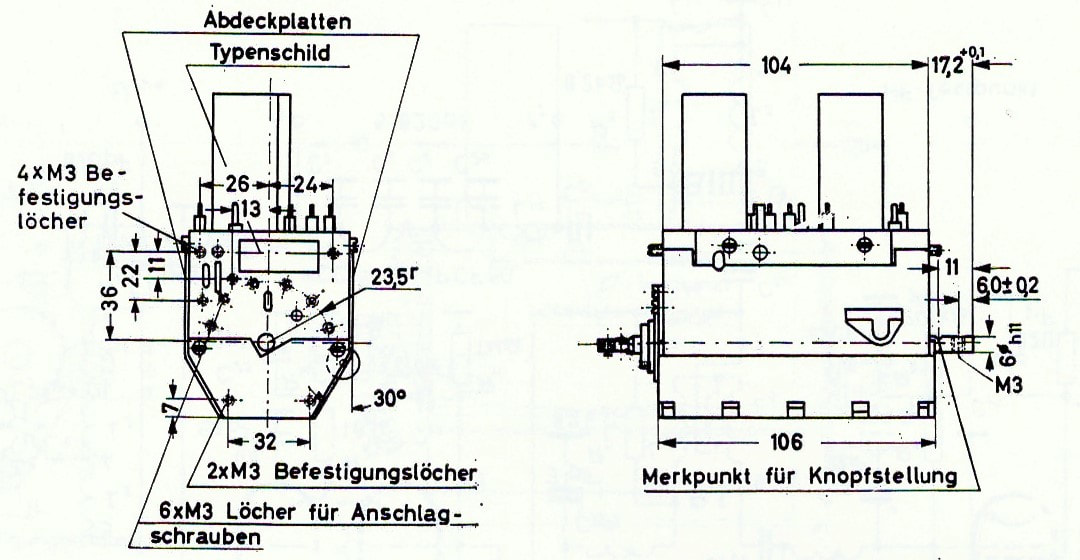
Official drawing of the new mechanics for VHF tuners, introduced with the AT7630 series. The main change was in the slanted bottom sides. [Valvo Kanalwähler, 1961]
|
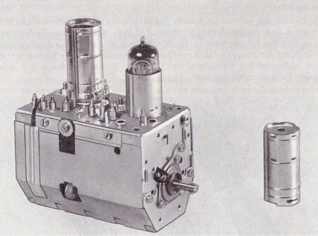
Picture of the AT7635, a standard European channel E2-E11 version. [Valvo Kanalwähler, 1961]
|
It seems that the printed coils were not introduced from the very first models in this new generation of tuners, so the AT7630-7633 were probably still using discrete coil "biscuits" like the previous generation. But rather quickly versions with printed coils appeared, starting with the AT7634. From the picture below it is clear that for the largest coils, with the highest number of windings, a fairly fine pitch PCB technology was required.
The Philips Service booklet introducing the AT7632 new tuner family with printed coils, February 1959. [Ite Weide]
Before we turn to the Memomatic, a quick glance at the circuit diagram of the AT7630 family. First order there were not many changes compared to the final circuit C from the KR 361 51 generation, but we will code the new basic circuit as D1:
|
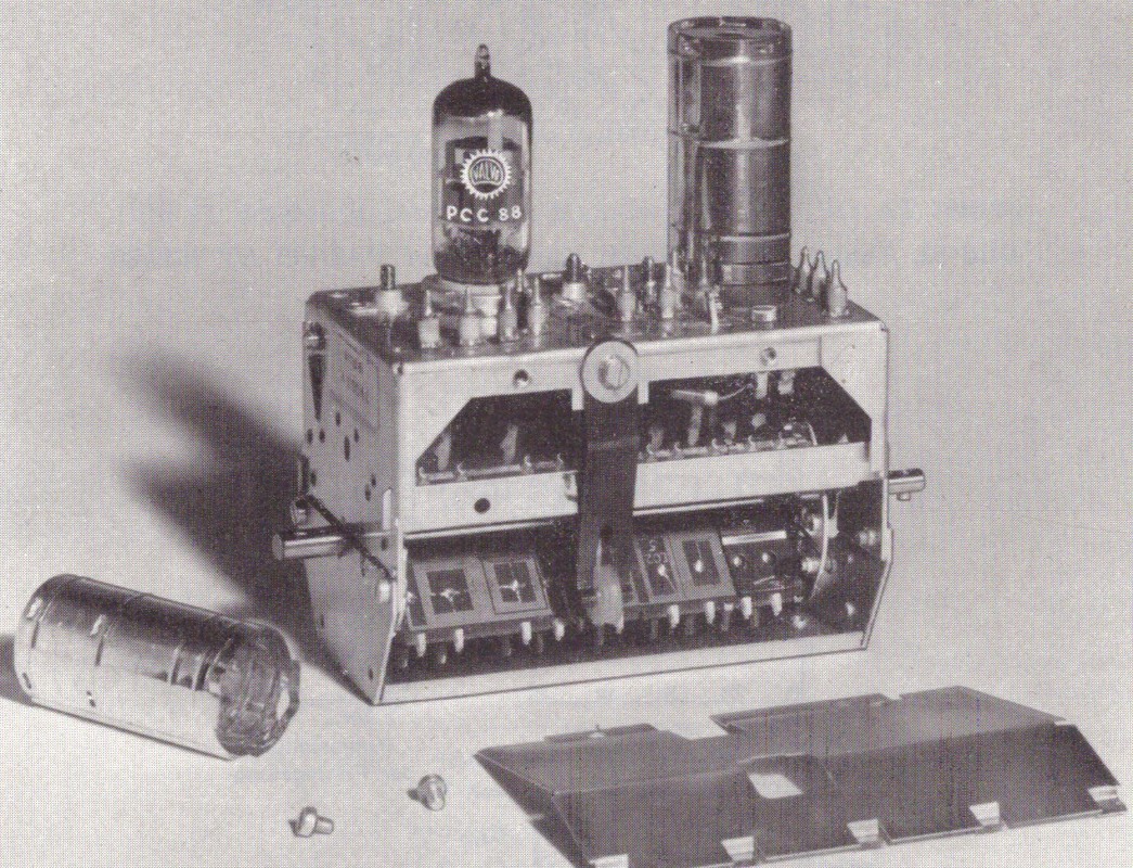
The AT7635 tuner with opened side, clearly exposing one of the printed coil filter modules on the revolving drum. [Valvo Kanalwähler, 1961]
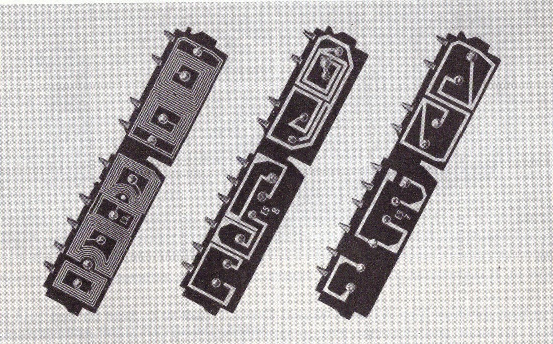
The new printed circuit board filter "biscuits" of the AT7634 and subsequent models. On the left a VHF-I biscuit with multiple loops per inductor, in the center probably the lowest VHF-III (channel E5) module, on the right the highest VHF channel (E11). [Valvo Kanalwähler, 1961]
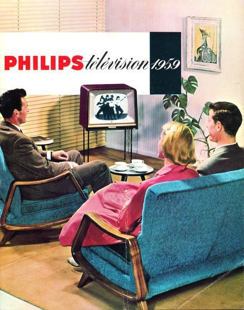
The new AT7530 generation tuner was introduced in the 1958-59 TV generation, with the TX220 as base family. The TX230 and TX240 were electrically identical, but featured more luxury front panels. [Philips Reclamekunst]
|
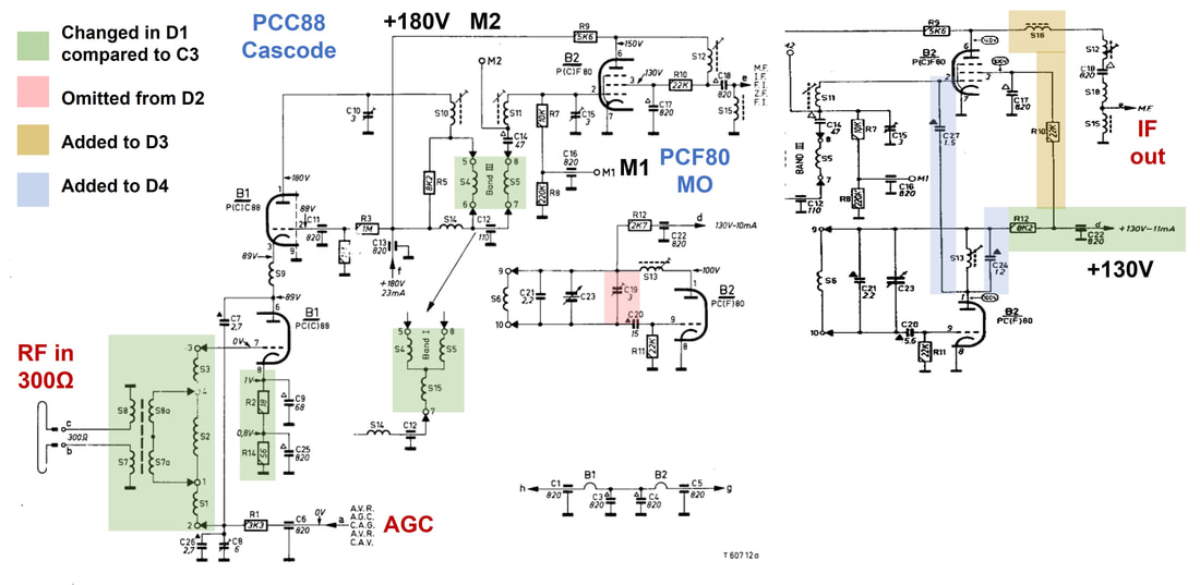
Circuit diagram of the Philips AT7630 VHF tuner family. Colours indicate the different changes over time. Note that this generation introduced two test points: M2 the "IF test" and M1 the "RF test". [Philips A3 790 30, AT7635 and A3 300 40 Service documentation]
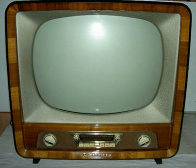
The first chassis to introduce the new AT7632 tuner were the TX220-230-240 families. The TX220 only had control knobs, the TX230 shown here also had push buttons for advanced feature control. Shown here is the luxury 21TX230 with also the channel selector control on the front side. [RadioMuseum.org]
|
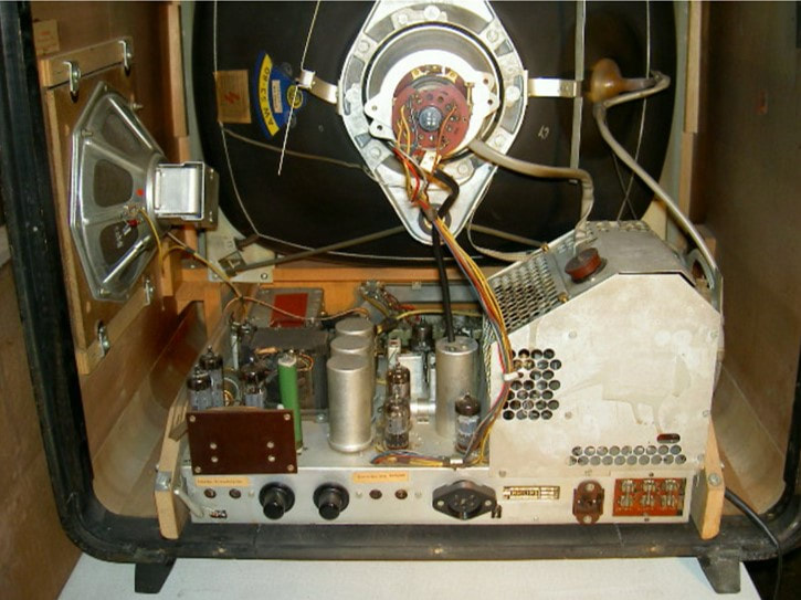
The TX220 chassis still used the same construction as the TX140-210, with the metal frame mounted on a wooden support with the tuner in front of the chassis. This made the cabinet relatively deep. Note the large HV cage. [ibid]
|
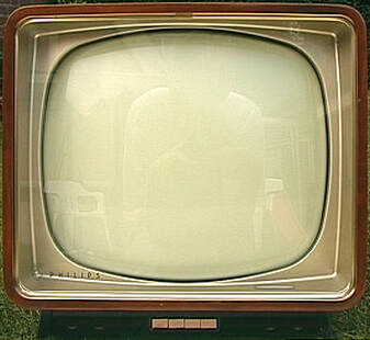
The TX250 chassis from 1958 introduced the new AW88 110 degrees picture tubes, which were flatter and less deep than the 90degrees tubes. The cabinet therefore could be fitted more tightly around the CRT, as compared with the TX220 above. This is the 21TX250A base model. [Marcels TV Museum]
|
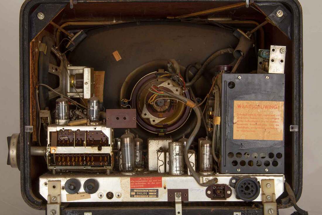
The interior set-up was made more compact to allow the less deep cabinets. The HV cage became thinner, allowing it to move forward next to the neck of the CRT. And the tuner module, here shown opened, moved on top of the chassis. This is the 17" 17TX250A. [Pa3esy.nl]
|
Towards the end of the 1950-ies the number of transmitted VHF channels increased rapidly. One consequence of this was the move to UHF, that will be discussed in the next chapter. A second, quite different effect, was the need to "remember" channel tuning conditions when changing between channels. Don't forget that with the television sets as they were at the time, the channel selector was a large rotary knob mostly on the side of the cabinet, with an outer ring for the fine tuning. Every time the viewer changed channel this had to be done manually, first selecting the channel, then the fine tuning. Over the coming years we will see many efforts to make channel selection easier. Since there was no way to store data electronically all these solutions were invariably mechanical by nature. The first one was the Memomatic or (in German) Memomatik.
|
The core concept of the Memomatic was to use a small bolt per channel (the orange arrow) for fine tuning, i.e. the setting of the oscillator tank circuit trimming capacitor C23. The tip of the bolt pushed a cantilever (orange, turning around the red axis) which pushed the core of the tuning capacitor C23 inside the box. Every channel has its own bolt, which were positioned on a circular plate on the central axis, 12 in total. The bolt was set once per channel, after which it was in the right position every time the channel was selected, acting as a mechanical memory.
A consequence of the new Memomatic mechanical construction was that it was deemed impractical to maintain the primary channel rotation know on the same front side of the module. As a consequence this function was "diverted" from the front to back face of the module through a set of beams and gear wheels, indicated in blue on the mechanical drawing. The Memomatic was thus an impressive mechanical piece of engineering, a first of more to follow. Despite the complexity, which hopefully didn't cause any reliability issues, and the associated higher cost, the Memomatic seems to have been a success, since it became a widely used feature in many successive tuner and TV generations. At the same time it could easily be deleted and replaced by a standard tuner, making it an interesting commercial selling feature. |
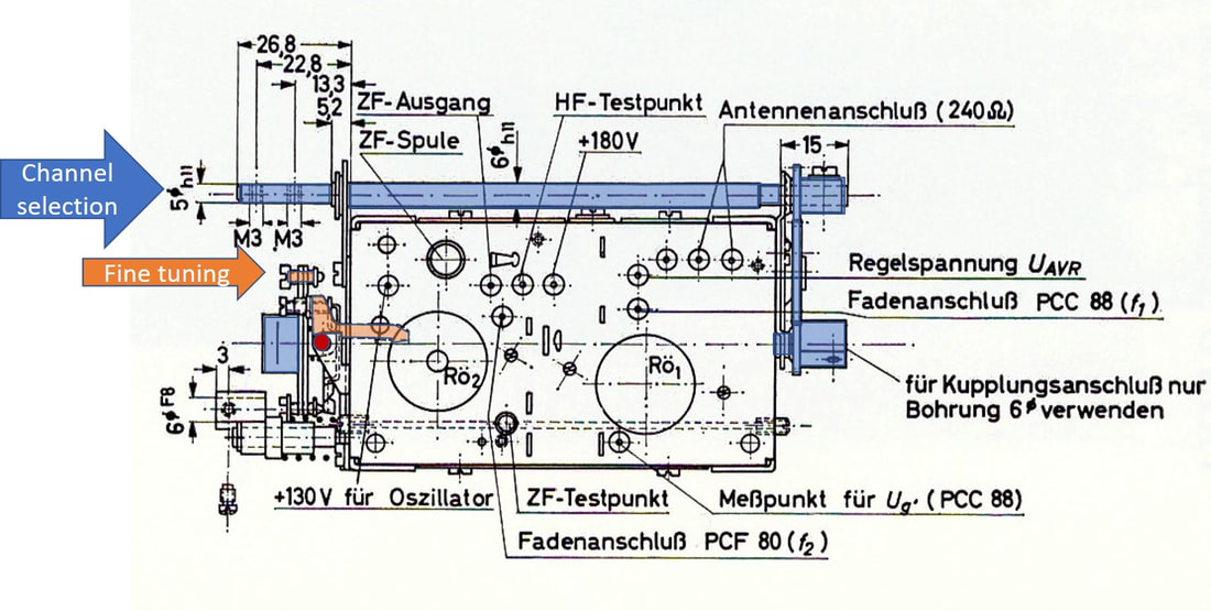
Top view drawing of the Philips AT7637 VHF tuner with Memomatic. Orange parts show the per channel fine tunng mechanical memory. In blue the "work around" of the primary 12-step channel selection rotary drive of the main axis. [Valvo Kanalwähler, 1961]
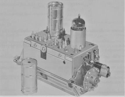
The Philips AT7637 VHF tuner with first generation Memomatic. On the right the disc with the 12 individual channel fine tuning bolts. The construction on the right with the spring is to push back the cantilever. [Valvo Kanalwähler, 1961]
|
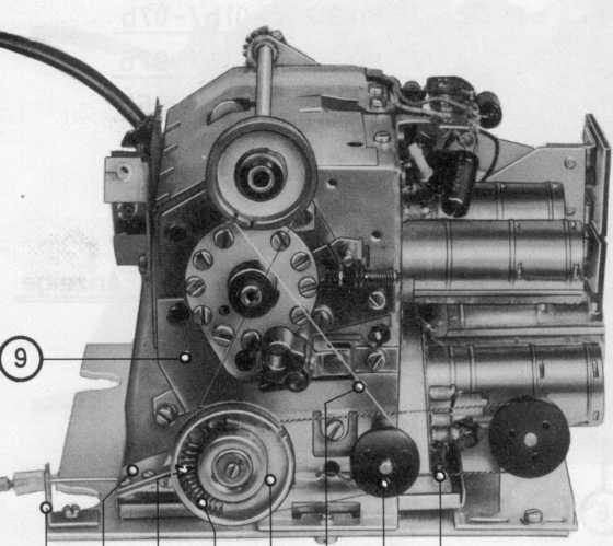
A complete VHF-UHF Memomatik unit using the AT7637 VHF tuner. [Radiomuseum.org]
The picture on the right shows the wiring of the knob and indicator strings. [Philips 21CD312A Service Manual]
|
A complete Memomatic tuning unit is shown on the left, a module from 1960 in most probably the 21TX310 or 21TD310. Above is an AT7637 or A3 300 40 VHF tuner, mounted horizontally on top of a first generation UHF tuner. Although the picture doesn't show the complete construction with respect to the control, it is clearly visible that the wheel on top is used for the VHF drum rotation as described earlier. The wheel lowest left is for the UHF tuning. Looking at the construction it is almost certain that the per channel fine tuning using the 12 screws had to be done by a service engineer, given that they don't seem accessible by the television set user.
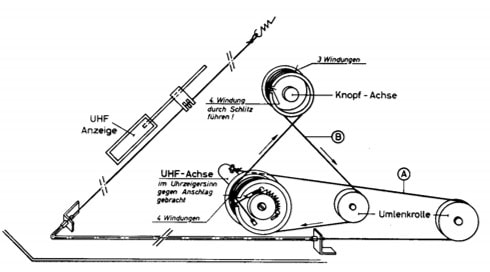
|
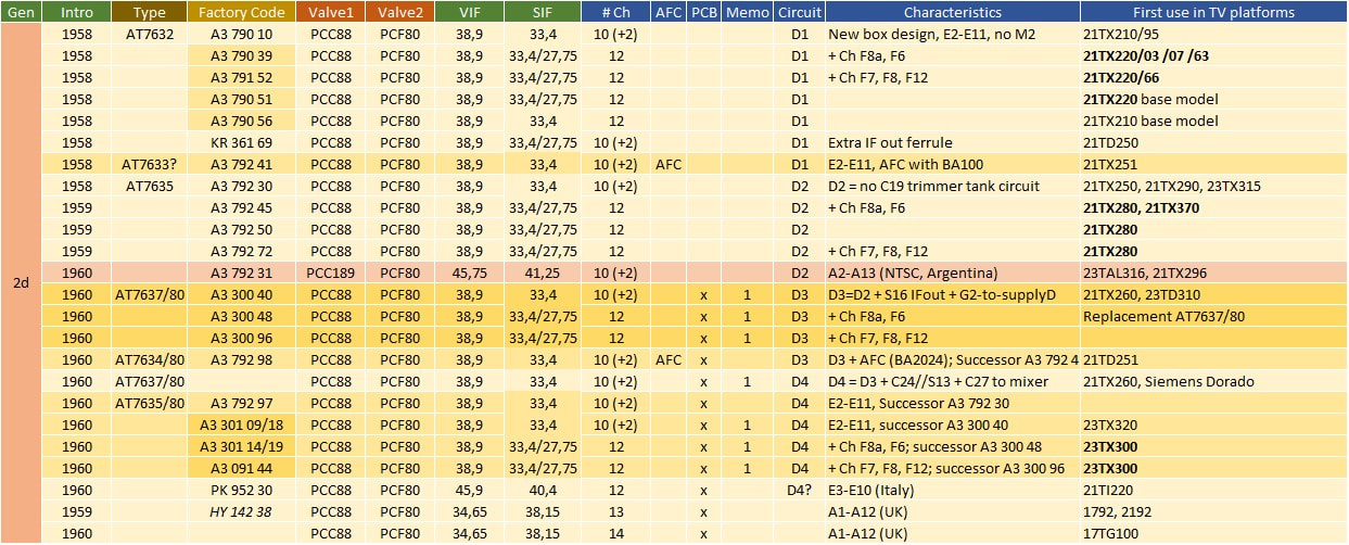
Overview of the expanding Philips AT7630 VHF tuner family, which introduced the new mechanics and later also printed circuit biscuits (column PCB) and the Memomatic tuning memory. TV chassis names in bold refer to 4-norm sets.
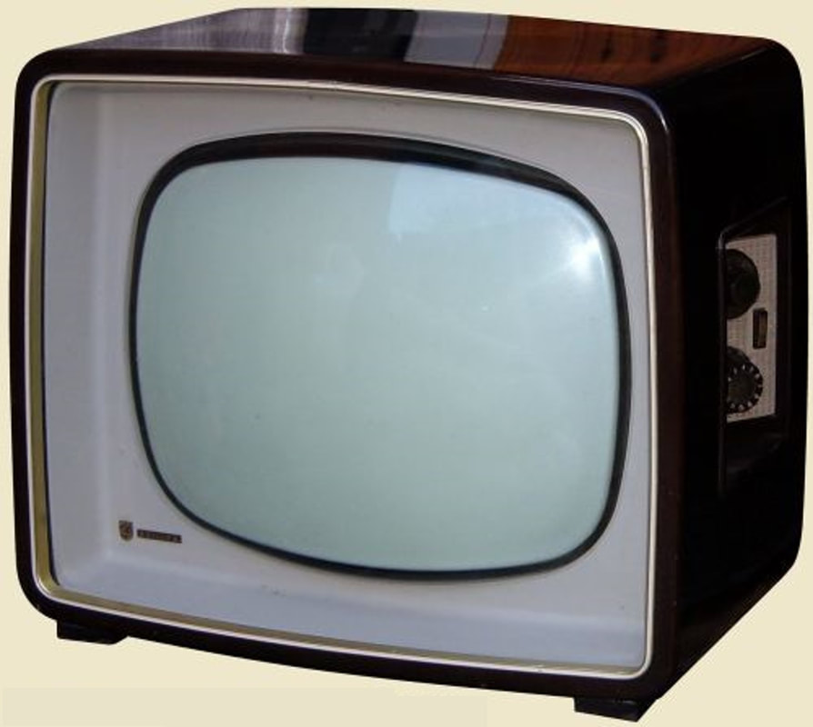
The Memomatic was quickly introduced in most countries, including the UK. This is the 17TG100, the first chassis where the UK started to comply with the Philips TV type naming convention. [The Valve page]
|
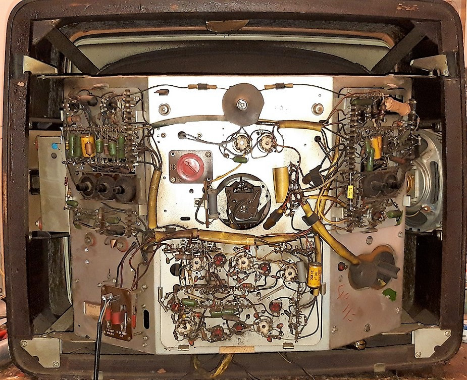
Although the UK Mullard/Philips organisation started to comply with corporate policy in terms of naming, chassis design was still distinctly different. Here the interior view of the 17TG100, with a chassis design not seen in any other Philips set. [Vintage Radio and TV Forum]
|
|
The table with the overview of the (initial) AT7630 family of VHF tuners shows a continuous expansion compared to the previous generations. Especially French and Belgian multi-norm solutions gave an increasing diversity, mainly due to the channels used. Halfway the entire family came the upgrades to the cheaper printed coil biscuits as well as the Memomatic option. And finally there were the locally produced tuners like in Italy and the UK.
And before closing this chapter it is interesting to get a glimpse at the prices of these tuners, form a September 1960 price list of Philips components for electronic hobbyists. It shows the AT7632 for Hfl60,00 an the AT7635 for Hfl65,00, confirming they were after the picture tube the most expensive electronic components. For comparison the complete high-voltage line output unit was Hfl30 and the deflection coil unit Hfl25. (The Hfl60 must have been around 60DM, 1200BFR, 180FF, 20GBP and 30USD at the time). Another source, however, mentions the price of the AT7635/80 (with Memomatic) as Hfl14,75, suggesting that the hobby price was 4 times the normal factory price. |
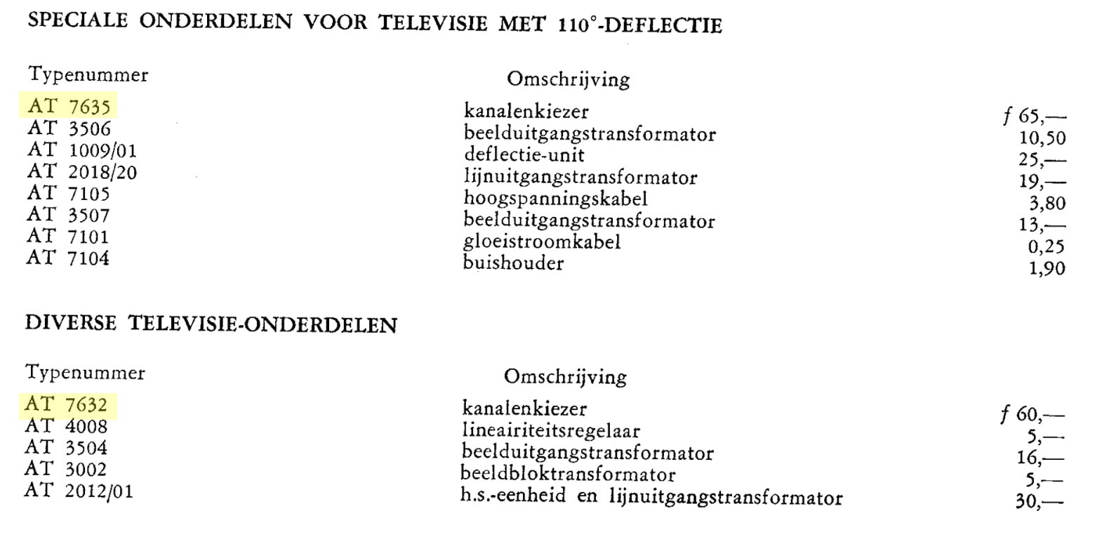
Prices in Dutch Guilders for TV components on the external hobby market from September 1960. My guess is that internal factory transfer prices must have been at roughly half these numbers. [courtesy Ite Weide]

1960 Philips TV advertisement. [Philips Reclamekunst]
|
Update history
August 2017
1st upload
October 2022
Added paragraph on Vision IF standardization, mainly based on discussions and input Steve "Synchrodyne" on Vintage Radio & TV Electronics Forum
October 2023
Due to the release of the Philips Technology History volume1, covering the 1950-1980 tuner history, the page has been reduced to the core tuner generations story. All background information can be found in the book.
July 2024
The page has been resored to its original content, but not including the additions and corrections that can be found in the book.