Introduction
|
Transistors had been invented in 1947, resulting in the introduction of Philips semiconductor diodes in 1950, although real production and the use in TV's only started in 1952 with the OA60 diode. The first germanium alloy transistor, the OC10, appeared the next year, but again real production was only possible with the second generation OC70. However, the application of semiconductors in TV's went slowly. Transistors were predominantly used in portable radios, and in all TVs up to 1964 only a handful of germanium diodes was used, mainly for audio and video detectors, supply rectifiers and an occasional switching circuit. And then, finally, transistors were introduced in 1964, and most surprisingly in the most difficult sub-module of the TV: the (UHF) tuner! It was only after this first step that the fully transistorized portable television appeared, followed by the standard TV's moving towards a hybrid transistor-valve architecture. To understand these developments we'll first have a brief look at transistors and their development in the 1950s and 1960s.
Once the transistor was introduced the channel selectors quickly became more compact, although the fundamental tuning mechanisms initially didn't change: drum tuners for VHF, variable capacitors for UHF. To allow finally new, all-electronic tuning yet another semiconductor element was required: the variable capacitor diode or varicap. When these were introduced in 1969 entirely new channel selection mechanisms could be developed, with touch buttons and ultimately remote controls. In the meantime a variety of mechanical channel pre-set and selection constructions was used. Both these developments were accelerated by the third - and most important - development of TV in this period: the introduction of colour. The introduction of colour TV standards by itself had only minimal influence on the tuner design, but the explosion of functional complexity associated with colour put an enormous pressure on both size and cost reduction of all other components inside the TV, including the tuner. This chapter will cover the period 1964-1980, with tuners entirely designed from transistors. In the meantime Philips continued to grow as one of the dominant players in consumer electronics, sweeping up many of its former competitors in the process. In many cases this started with selling components (the picture tube and tuner, valves and semiconductors, discrete components), followed by complete reference designs and copy production of these platforms. By that time usually only a brand name was left, when the company was acquired by Philips, often continuing the use of those brands for quite a while. These acquisitions included companies in increasingly remote countries, like the South America, Australia and South Africa. Which in turn made for an ever wider portfolio of tuners, covering all different standards across the globe. In this decade we're therefore even going to see two Philips divisions active in developing and producing tuners: consumer electronics (RGT) and components (Elcoma). All in all much to discuss! |
Chapter Navigation
|
Germanium RF Transistor development
In the context of this story it goes to far to dive into the fundamentals and details of the transistor, and the basics are assumed to be known, like I did for the valves in the previous period. I'll therefore focus on the specifics of the tuner application: the RF transistor. For the moment we only need to consider the "mother of all transistors", the Bipolar Junction Transistor (BJT), as it was invented at Bell Labs in 1947. A summary of the early Philips diode and transistor development has been presented as part of the early television development here, and we'll continue where that story left us in 1955. The first Philips transistors, based on a patent licence from the US company RCA, were based on the so-called alloy junction concept using germanium as the base material (see below picture left). The transistor was constructed from a thin 15um thin N-doped Germanium wafer, to which on the top and bottom drops of Indium were attached through an alloying process at some 250 degrees C. This resulted in p-type diffusion layers at the interfaces, resulting in a P-N-P structure. As can be seen from the picture, dimensions were fairly large, and these transistors could thus only be used for low frequency and audio applications. This type was introduced in 1954 with the OC44-OC45 and would continue till around 1958 with the OC71-72.
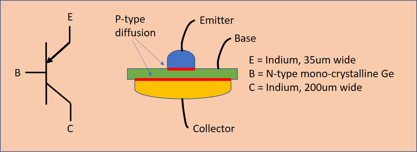
Conceptual drawing of the first generation germanium alloy junction PNP transistors produced by Philips as OC44-45 and OC71-72.
|
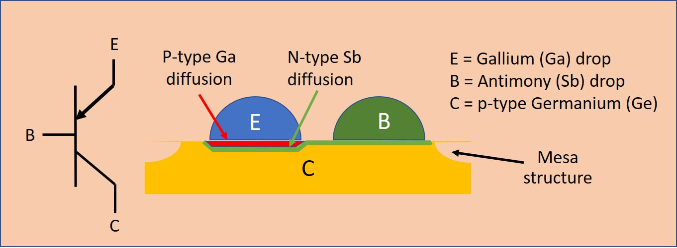
Conceptual drawing of the 2nd generation alloy diffusion germanium PNP transistor developed by Philips and Mullard, and introduced with the OC169-170 and 171 in 1959.
|
With the introduction of the new European naming convention another novelty was introduced: common types. Up until then each company had developed its own transistor variants, although in practice they might be very similar. This was especially the case with Philips/Valvo and Telefunken. Now, like was the case for many valves, a "standard" performance was defined for a common type transistor, which could then be produced by multiple companies. Examples of RF transistors were the AF106, AF121 and AF139. However, since the common specs could be rather widely defined, in practice companies created dedicated sub-types within the common spec envelope, e.g. with more tightly specified performance and/or binning. An example is the common type AF106, which we won't find in Philips tuners, but instead the compatible AF178 and the binned AF180 (150MHz fT).
The first AF-type transistors still had modest RF performance: the AF106 an fT of 150-180MHz, the AF121 an fT of 270MHz, which made them usable for VHF at best. UHF had to wait for the AF139, a 500MHz transistor, although also here the highest operational frequency was very close to the fT, with the associated performance degradation at the upper end of the band. The AF139 was developed by Siemens on the request of the Grundig tuner group, and it seems that Philips initially used the Siemens transistors. Only later the AF139 became a common type, while Mullard developed the compatible AF186. Especially the widely-used AF186 was produced in a number of binned (selected) versions AF186/81 to AF186/84.
The first AF-type transistors still had modest RF performance: the AF106 an fT of 150-180MHz, the AF121 an fT of 270MHz, which made them usable for VHF at best. UHF had to wait for the AF139, a 500MHz transistor, although also here the highest operational frequency was very close to the fT, with the associated performance degradation at the upper end of the band. The AF139 was developed by Siemens on the request of the Grundig tuner group, and it seems that Philips initially used the Siemens transistors. Only later the AF139 became a common type, while Mullard developed the compatible AF186. Especially the widely-used AF186 was produced in a number of binned (selected) versions AF186/81 to AF186/84.
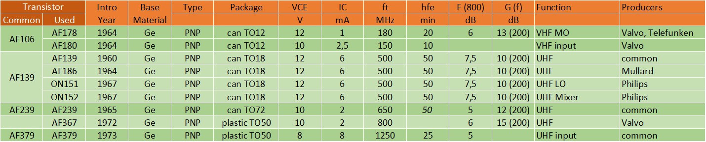
Overview of the germanium alloy transistors produced by Philips, Valvo, Mullard and La Radiotechnique and used in the Philips TV tuners.
AT6370 and AT6380, the first UHF transistor tuners, 1963
The pressure on the development groups of transistor tuners was obvious: provide smaller, and thus material-wise (much) cheaper tuners with a performance at least equal to that of the then optimal valve tuners. I'm sure that an integral cost that was almost equal to the valve tuner was acceptable for the first generation, price erosion would come with volume. Simple as it may sound, this was no easy task! On the one hand the latest generation valve tuners had become very good, especially in VHF with the PC900 and PCF801 frame grid valves. And although the noise performance of the PC88-PC86 combination at especially the upper UHF band edge was not spectacular, the performance of transistors on this parameter was not better at all!
|
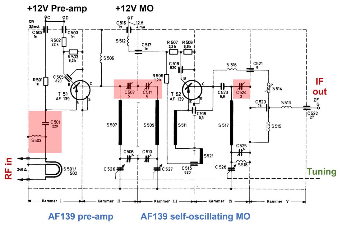
The very first effort at a transistorized UHF tuner was literally a valve tuner in which the triodes had been replaced by AF139 transistors; if we compare the AT6370 schematic diagram on the right the resemblance with the AT6322 is remarkable. Note that because of the PNP transistors the collectors are grounded and the emitters on +12V. The conceptual set-up was therefore also identical: a first common base RF pre-amplifier followed by a double tuned BPF, and finally a self-oscillating common base MO. All this using three tuned sections as in the valve tuner. Even the mechanical design was very similar, with the two metal cans of the transistors protruding through the can top.
It is likely that performance of this very first tuner was still mediocre, since it was initially only used very briefly in just two German TV sets, the 23TD341 and 42. These were the German versions of the 23TX401A with the advanced motor controlled tuning system. In 1964 a slightly optimized version using the new AF186 transistor was used in Eindhoven in the 1964 TV platforms. |
The Philips AT6370 UHF tuner, the first transistorized version. The components shaded red were to be changed or deleted in the next generation AT6380. [Philips AT6370 A3 345 89 Service Manual]
|
Very quickly the AT6370 was superseded, however, by the AT6380, essentially an optimization. The main drawback of the 6370 has probably been bad noise performance at the higher portions of the UHF band. As we've seen the fT of the AF139 was 500MHz under typical conditions, possibly a bit higher when pre-selected and/or optimally biased. Roughly speaking the Noise Figure of the transistor will start to increase inversely with the degradation of beta beyond fT/beta, due to the increasing effective input capacitance of the transistor. This can only be countered by tuning out this capacitor with an inductance, and this exactly what we see in the AT6380: a fourth tuned filter in the form of a input BPF, similar to the typical VHF input. So the changes were:
- using 4 instead of 3 tuned filter segments (so now input, double tuned BPF, oscillator tank circuit)
- reduction of the number of capacitive alignment trimmers (red in the AT6370 circuit diagram)
- relocation of the transistors from the top of the box to the centre
- the internal gear was deleted and the control axis moved to the other side of the box near the RF input. This was to facilitate more direct control of push button pre-set assemblies that will be discussed later
- smaller height of the module.
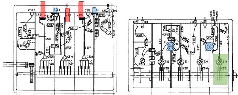
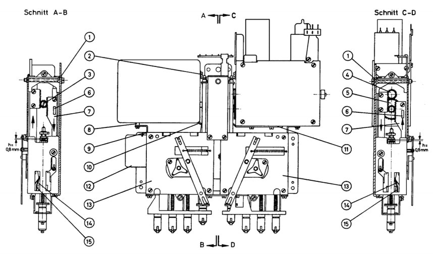
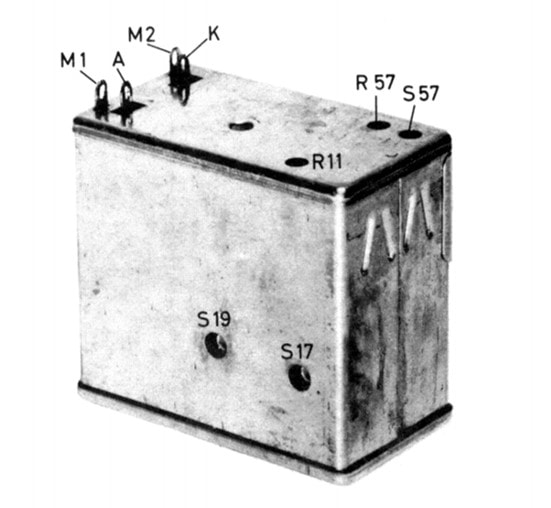
Mechanical drawings of the Philips UHF tuners AT6370 (left) and AT6380 (right). Red are components deleted from the AT6370, green the new input tunable section. Blue shows the change of location of the transistors. [Philips AT6370 and AT6380 Service Manuals]
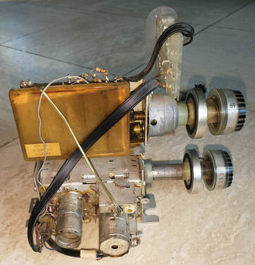
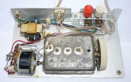
The Philips AT6380/01 UHF tuner mounted on top of a AT7650 VHF tuner. Production code PT 5120 indicates it was produced in Portugal in 1965, probably week or batch 12. [Pieter Hooijmans private collection]
|
|
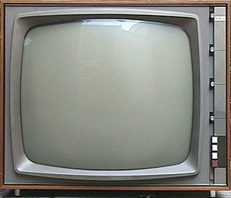
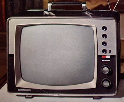
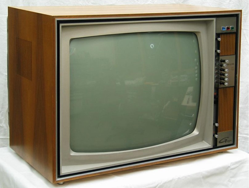
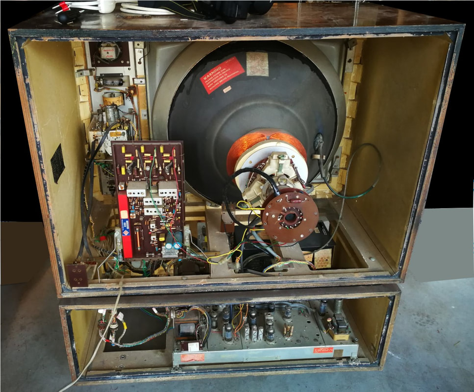
A typical 1965-66 high end Philips TV set. This is the 23TX561A, a Belgian multi-norm set. [Marcels TV Museum]
|
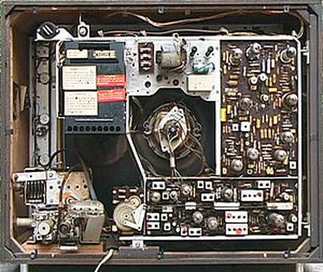
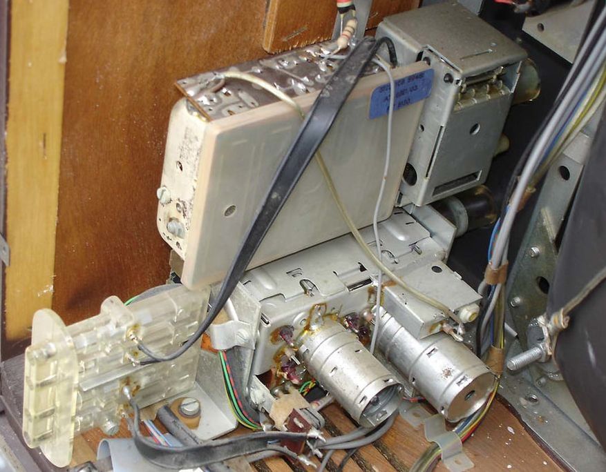
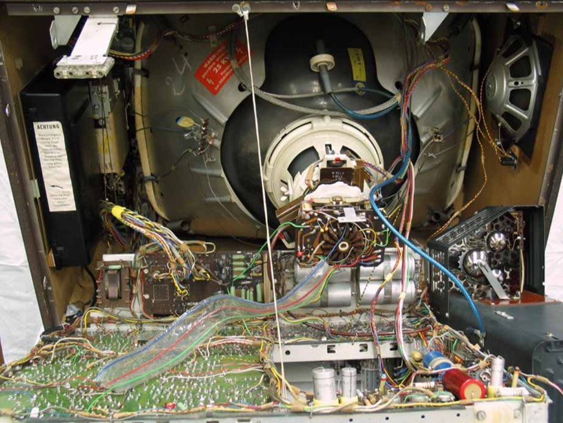
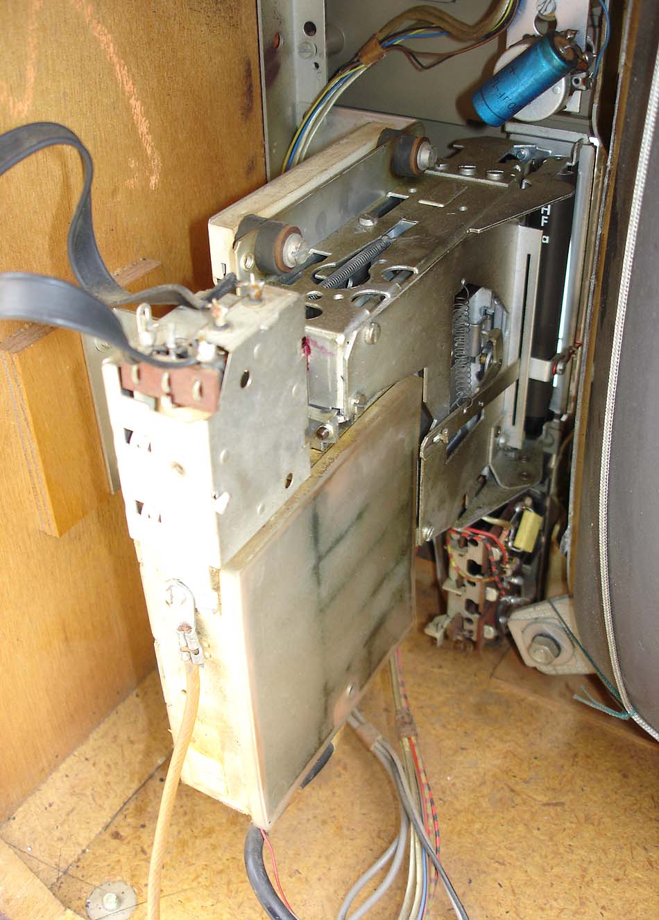
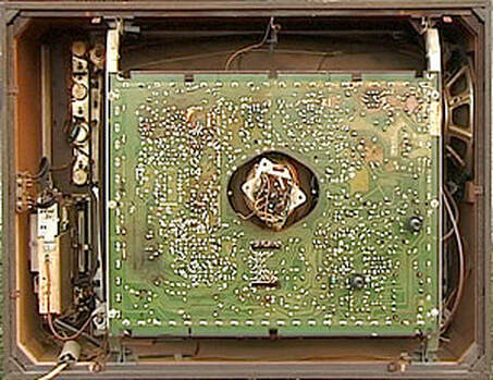
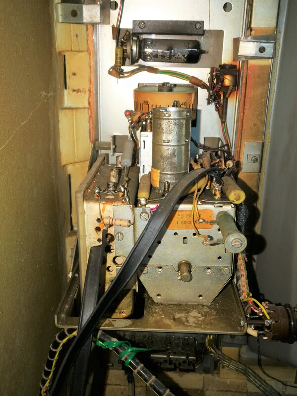
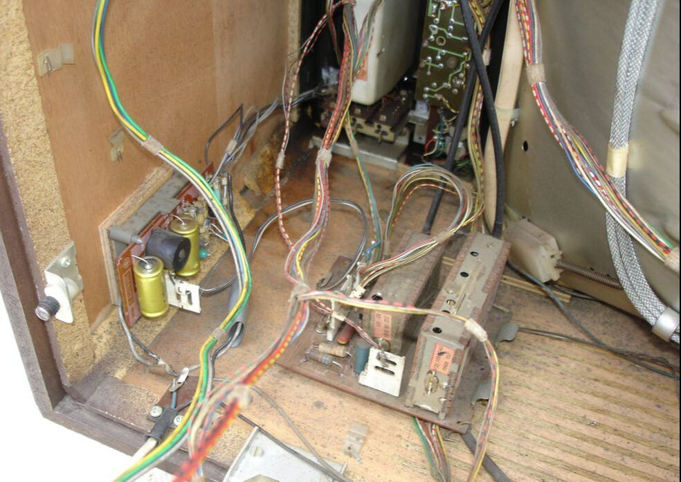
Interior view of the Philips 23TX561A. Lower left the VHF-UHF tuner stack including channel pre-set mechanisms. Lower right the motor-controlled multi-norm IF board. [Marcels TV Museum]
|
The AT6380/01, or the U5 as it was also called, was introduced in Dutch and German sets first, and used in all 1965 chassis, introducing the push-button channel selection and pre-set that will be discussed below. A similar tuner but adapted for 75Ohm asymmetrical RF input was simultaneously introduced in France (AT6380/30) and the UK (AT6380/02). The latter was the first to introduce the new generation Ge alloy diffusion transistor AF186, which was especially promoted by Mullard. Most likely through a size reduction the AF186 was the first to have an fT well above 500MHz; the minimal spec for the common type AF139 was 500MHz, but data sheets suggest selected transistors could reach 800MHz. (The naming AF186/81 to /84 that can be seen refers to different selection criteria for the transistor). So where the first AF139-based versions specified a Noise Figure of <12, the AF186-based version gave a typical NF of 8.5dB at 470MHz and <11.5dB at 860MHz. But quickly a cost reduction was introduced in the form of the AT6381, which had most DC resistors moved out of the box to a small PCB on top of it, thus reducing the amount of difficult component mounting inside the small chambers of the UHF module. AT6381 tuners were initially made using the AF139 (versions /01), later with the AF186 (versions/03). Especially in France many versions of this tuner were used.
In 1968 two final upgrades were introduced: the Eindhoven organization launched the AT6382, using the latest AF239 transistor for the RF input stage. This reduced the typical NF by some 1,5dB: 7dB at 470MHz and 9,0dB at 860MHz, although the maximum specs didn't change spectacularly (at 8,5 and 11dB, respectively). The UK Mullard organization was the first to introduce silicon epitaxial transistors in the AT6381/02, the BF180 and 181.
In 1968 two final upgrades were introduced: the Eindhoven organization launched the AT6382, using the latest AF239 transistor for the RF input stage. This reduced the typical NF by some 1,5dB: 7dB at 470MHz and 9,0dB at 860MHz, although the maximum specs didn't change spectacularly (at 8,5 and 11dB, respectively). The UK Mullard organization was the first to introduce silicon epitaxial transistors in the AT6381/02, the BF180 and 181.
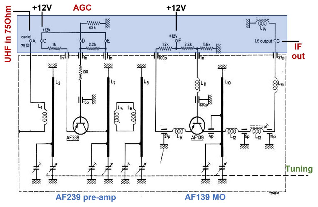
Circuit diagram of the French version AT6382/30 Philips UHF tuner, introducing the AF239 transistor. The blue section indicates the PCB and the externally mounted components. [Philips Elcoma Data Book CM3, January 1969]
|
The Philips AT6381/01 tuner, with the small PCB on top for most of the DC resistors, substantially reducing the internal density of the module [Philips Elcoma Databook CM3, 1969]
|
|
Also based on the new transistor UHF module a converter box was designed, as successor of the valve-based NT1152. As soon as the AT6370 was available a modified module was made with VHF channel 3 or 4 as output instead of the TV IF. The UVC2, as the module was called, thus used a three-section tuner, although it introduced the AF186 transistors. The tuner contained the internal gear, so tuning was done using a big thumb wheel. On the non-geared axis of the variable capacitors, exiting on the other side of the tuner, the channel indicator was mounted.
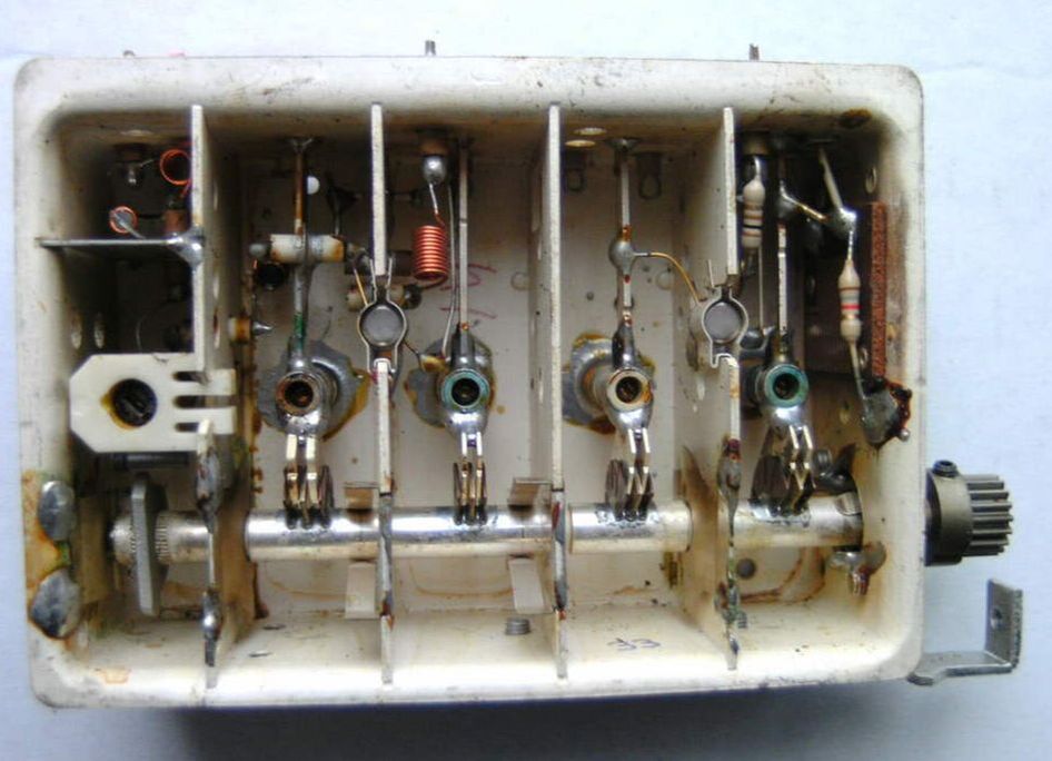
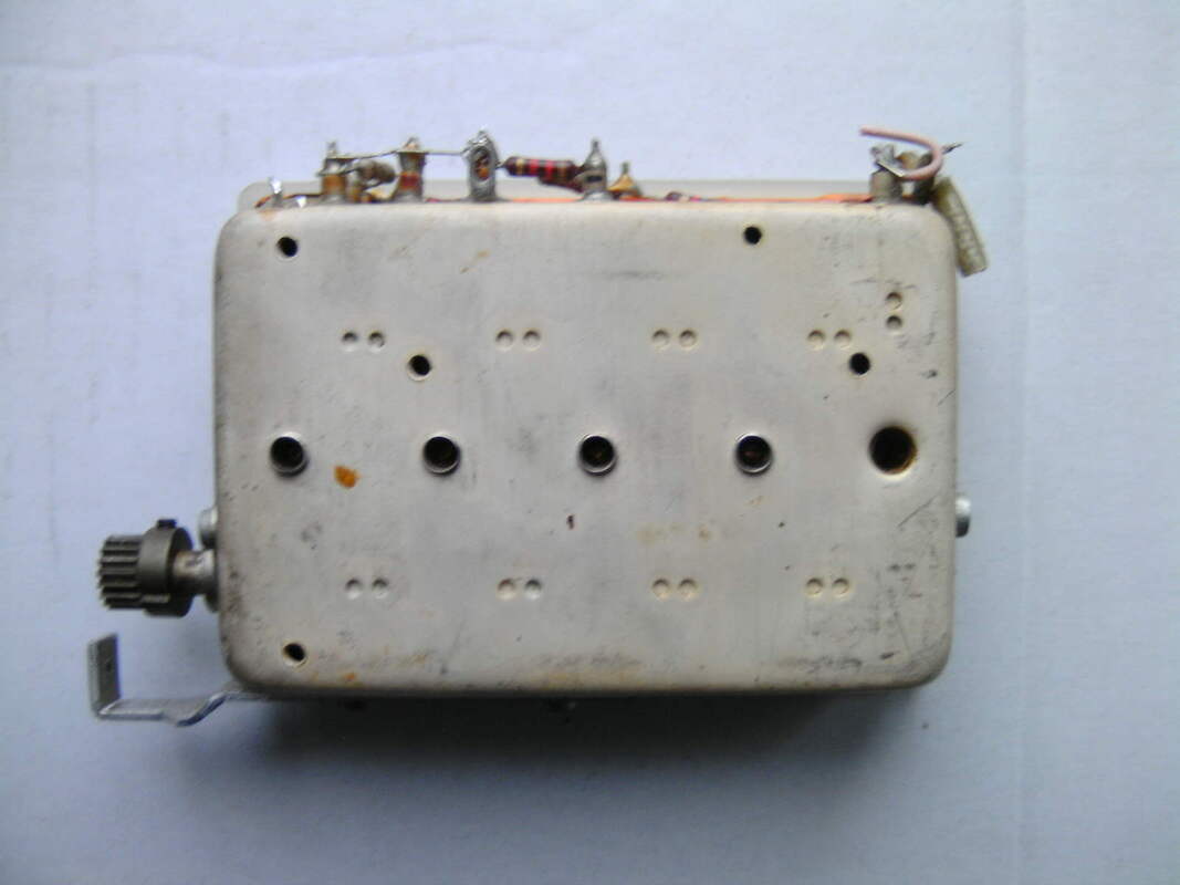
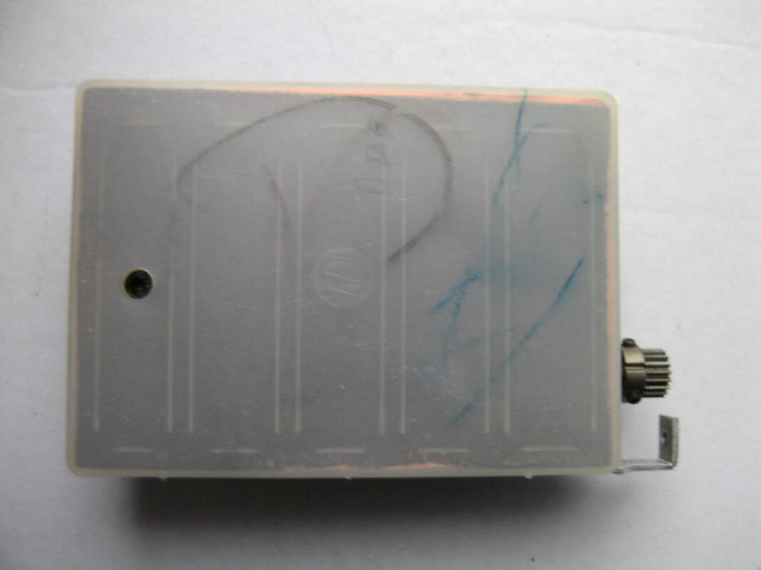
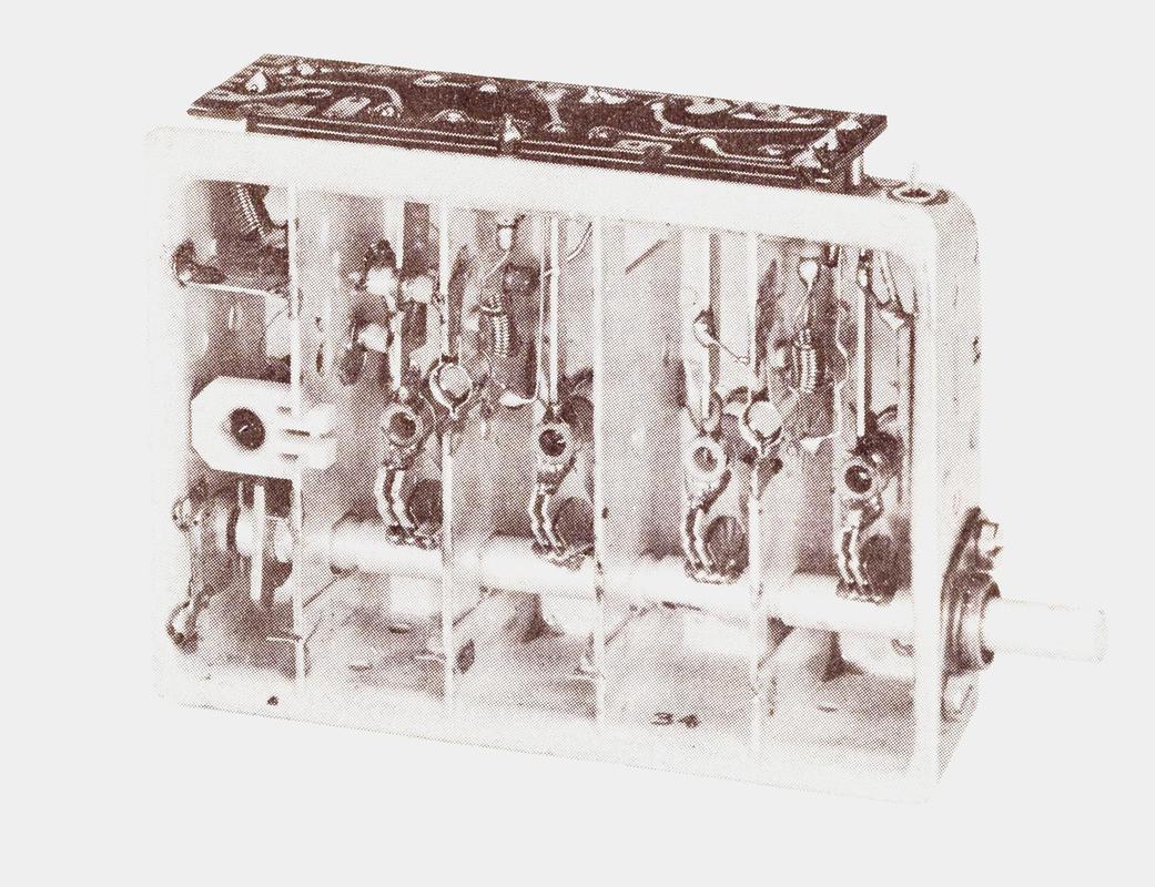
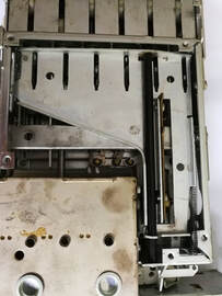
Interior view of the UHF module inside the UVC2, showing it is a 3-section module derived from the AT6370. [idem]
|
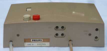
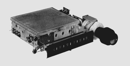
Backside of the Philips UVC2 UHF-to-VHF converter box from 1964. On the right the antenna input, centrally the two (switched) VHF and UHF outputs. [Ite Weide collection]
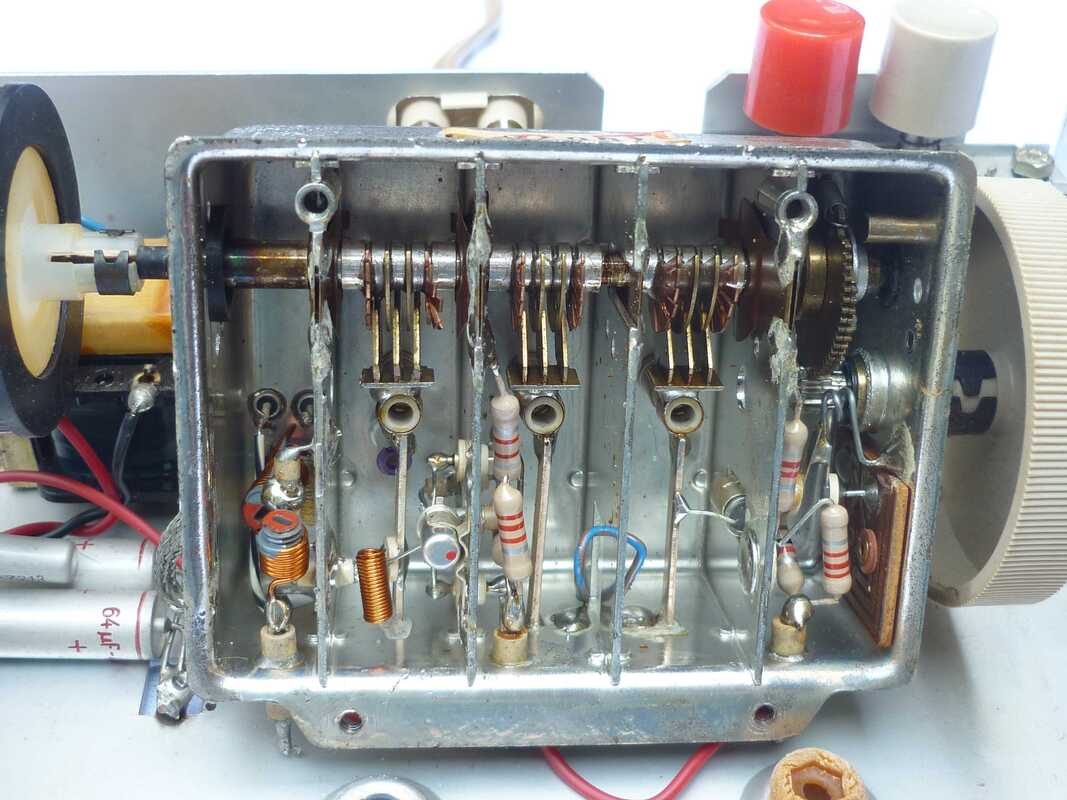
Interior view of the Philips UVC2. On the right of the tuner the geared thumb wheel, on the left the black channel indicator wheel. [idem]
|
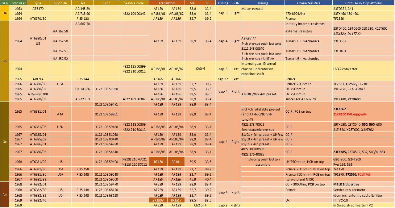
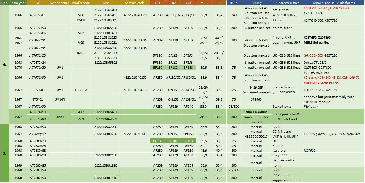
Overview of the Philips AT6380 family of UHF tuners, also called U5, and the first using germanium alloy diffusion RF transistors. In this period naming of components was still very diverse as can be seen: type numbers (AT6380), generation names (U5), old-fashioned factory codes (HA, A3, F), new component 12nc's (3122) and service 12nc's (4822). Furthermore they could refer to the tuner, the push button mechanics or the two combined. In the column TV platforms bold refers to Belgian multi-norm sets, italics to small screen portable sets. Red indicates the first Colour TV sets.
New pre-setting mechanics, 1963
Initially nothing changed in the appearance of the television set after the introduction of transistor-based UHF tuners. They were slightly more compact than the previous valve-based versions, but nevertheless mostly still mounted on top of the VHF module. The two buttons for VHF and UHF channel selection would still protrude through either the right side or the front panel of the TV set, depending upon design and the size of the screen relative to the cabinet. With the AT6380 a small module was introduced that could be mounted on the UHF tuner axis, with which up to four channels could be pre-set. Essentially these were four circular discs with a notch, which could, while pre-setting, slip around the main axis. During quick channel selection they would lock into position once a spring-operated bracket would lock to the notch. In parallel the ultimate solution for multi-norm Belgian receivers was introduced in combination with the AT7650/80. On the main axis of the VHF tuner a construction very similar to the internal Memomatic was used: 13 small teflon screws that pushed out a switch bracket. Only here there were three discrete positions, in contrast to the continuous "analogue" movement of the internal tuning screw. The bracket operated a three-position switch for the different TV standards (B, C&F and E). This was the last and ultimate multi-channel solution based on the rotation and drum-based tuners.
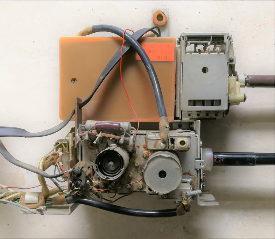
Typical 1965 tuner arrangement from the 23TX562A multi-norm set, with at the bottom the valve-based AT7650/86 VHF tuner with attached norm-switch and above it the AT6381/01 UHF tuner. On the latter the 4-channel pre-set module is visible on its axis. [Oswald Moonen collection]
|
The same arrangement, but now in a front panel configuration within the 19TX531A where there is room next to the picture tube. Again, the 4-channel pre-set is mounted on the UHF tuning axis. [Marcel's TV Museum]
|
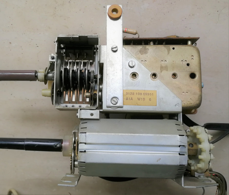
The ultimate turret VHF plus UHF tuner assembly, both with channel pre-setting. Below the AT7650/86 with internal Memomatic channel frequency pre-set and on the backside the Belgian norm pre-setting mechanism. On top the AT6381/01 UHF tuner. [Oswald Moonen collection]
|
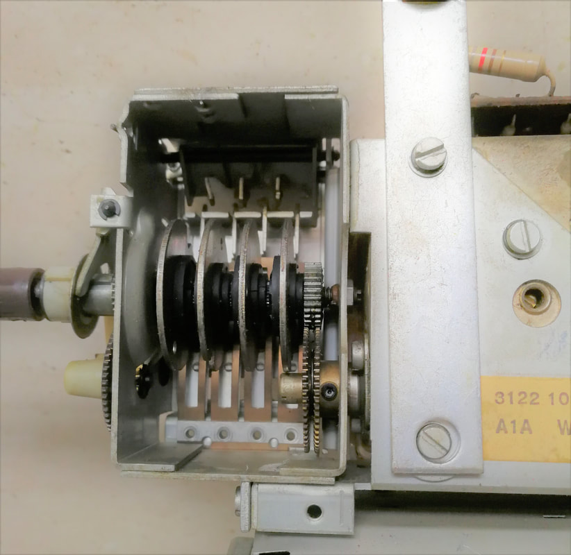
Close-up of the AT6381/01 4-channel pre-setting module. The four disks with the black plastic sliding notch mechanism are clearly visible. [ibid]
|
|
In parallel, however, new ways of channel memory and pre-setting were emerging, although modestly and only applied in high end sets. Both in Dutch and German sets the new 4-channel push button mechanics were introduced in 1965. In the new AT6380 tuner family all internal gear arrangements were deleted, and the tuning axis only rotated through 180 degrees, tuning over a range of 400MHz between 470 and 860MHz. Assuming a required absolute tuning accuracy of 400kHz (this is the formal maximum drift specification of typical tuners in this period), this translates to an angular accuracy of 400kHz/400MHz*180 = 0,2 degrees, which is not much and asks for some robust mechanical design.
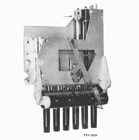
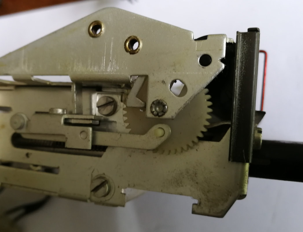
The core of the push button units were the threaded spindles (5). By rotating the knob-spindle combination when pressed in, the bolt on the spindle would move inwards or outwards to the channel pre-set position. These bolts in turn pushed an upper slider moving along rod (11), with a dented rack (14) attached to the slider that would rotate the tuner tuning axis through a mounted gear wheel (see the inset drawing). For counterbalancing a lower slider with rack 15 moved in the opposite direction. Since we've seen that the required angular accuracy of the tuning axis was 0,2 degrees, the construction had to be solid and rigid, and all in all it was a serious piece of mechanical engineering. 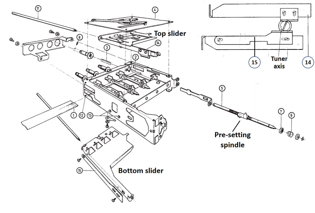
Mechanical drawing of the 4-channel push button preset module for UHF in combination with the AT6380 tuner. Note that we're looking at the back side of the module! [Philips 23TX532 Service Manual]
In 1965 a number of high end TV's were launched introducing the UHF 4-channel push button pre-set mechanism, while maintaining the standard drum tuner for VHF. Ignoring the one-off motor-controlled tuner the previous year, this was the first time a more convenient way of (UHF only) channel selection was introduced! We'll see that this new method quickly take over from the rotational channel selection in the coming years.
|
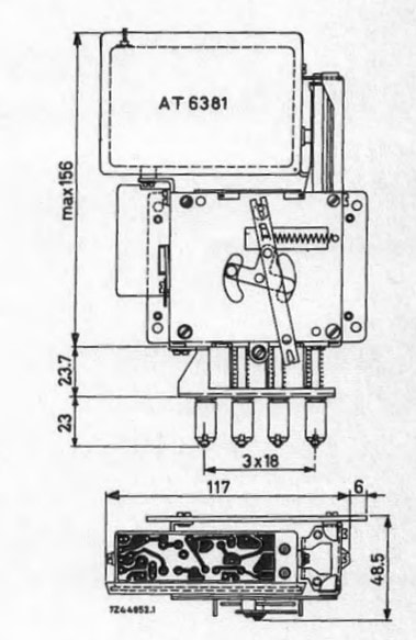

The Philips AT6385 module, comprising of the AT6381 tuner plus the 4822 276 40025 4-channel push button pre-set switch. On top a drawing, below a picture. [Philips Elcoma Databook CM3, January 1969]
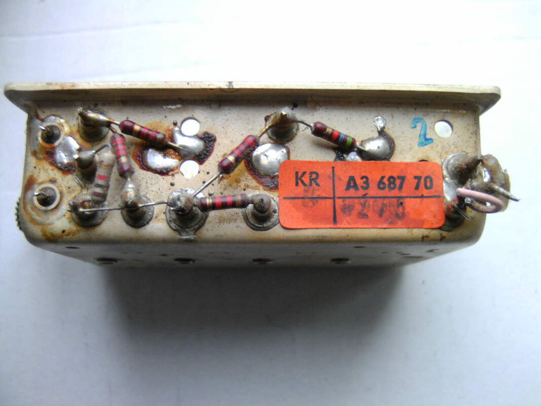
The German precursor of the AT6385, the HA 352 50, consisting of the HA 363 58 tuner and the A3 687 77 push button unit. [Philips UHF Drücktastensatz Service Manual via Radiomuseum.org]
|
AT7652, the first transistor VHF tuner, 1964
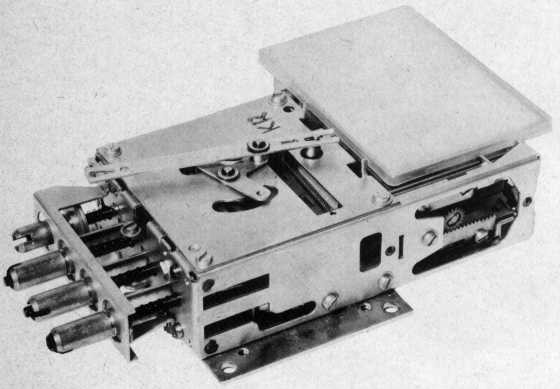
By 1964 the need for Philips to launch an all-transistor television was becoming urgent, given that some competitors had started already three years earlier. Therefore also an all-transistor VHF tuner was required, and it seems that a crash action was started to obtain such a tuner as soon as possible. The resulting AT7650T was for 90% identical to the valve AT7650; identical housing and mechanics with a 13-position drum and internal Memomatic fine tuning. The PC900 pre-amplifier was replaced by an AF180 in a similar common base circuit, while the oscillator and mixer sections of the PCF801 were replaced by one AF178 each. Although the overall concept was very similar to the valve version, there were a number of noteworthy circuit issues:
- the transistors, with their TO12 metal can housings, where mounted in the same way as the former valves through the top of the tuner frame, thus protruding to the outside.
- in contrast to the valve tuners, the input matching inductor on the biscuits (S8) was in a parallel-to-ground arrangement, instead of the standard serial input match.
- because of the PNP transistor type, the base voltage Vb of the AF180 is at roughly 10V. For AGC action the base voltage is lowered to maximum 8V, thus increasing the emitter current from the normal 2,5mA to 8mA and reducing the gain by 40dB.
- the secondary of the double tuned BPF is not grounded, but floating due to C12 and C13. Also, where in all previous valve tuners many measures were taken to isolate the primary from the secondary of the BPF, here a bridging resistor (R11) is applied.
- in contrast to most valve tuners, the oscillator-to-mixer coupling is not inductive through the biscuit coils, but capacitive through C14 directly to the mixer emitter.
- it is remarkable that this tuner can not be used as an IF loop-through for the UHF IF, as was common practice for the previous two generations AT7639 and AT7650.
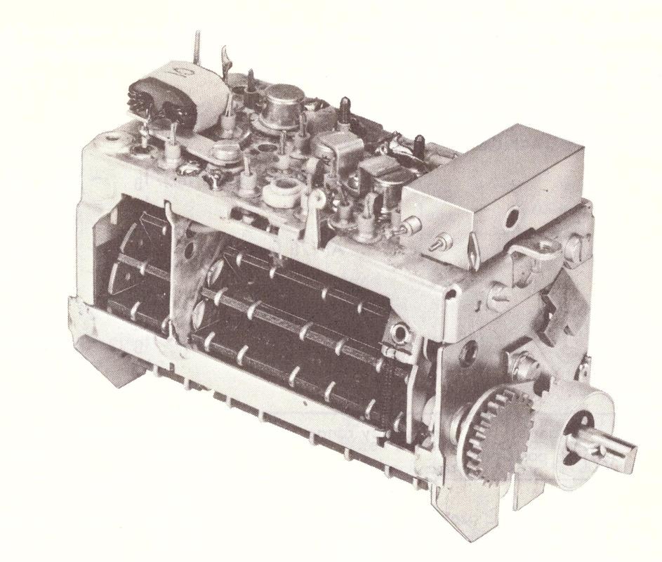
The Philips AT7650-90T, the first Philips transistor VHF tuner. [Philips AT7650/90T Service Manual]
|
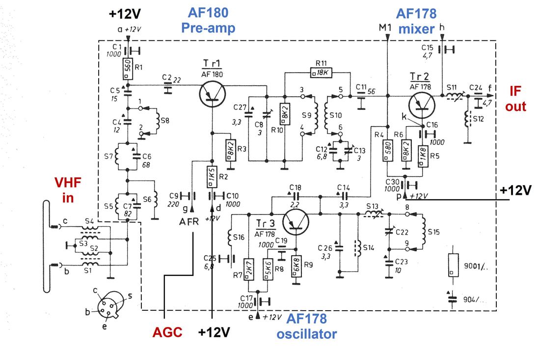
Circuit diagram of the Philips AT7650/90T. [Philips AT7650/90T Service Manual]
|
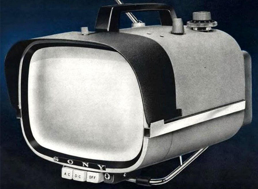
The TV that shook the world: the 1961 Sony 8-301W all-transistor battery-fed portable TV. Although it looked like a vacuum cleaner it was a big success and established Sony as a player in the TV market and leader in miniaturization. [Radiomuseum.org]
|
It seems that the 1964 Philips 19TX430 Rafael Luxus All-transistor was mainly a one-off answer to the Sony challenge, showing that Philips could also make portable all-transistor TVs. To make that point, it had a twice larger screen (19"). [Radiomuseum.org]
|
The first AT7650T was quickly followed by the AT7652T, with a number of modifications:
- the input matching inductor on the biscuits was again in series with the input;
- the BPF top bridging resistor was deleted, as was the floating secondary side, which were replaced by a common foot inductor (S19);
- the UHF IF input was re-introduced, using the mixer AF178 again as IF amplifier in UHF mode. Switching was done electronically using diode GR1, which was made conducting in UHF mode.
- The UHF input circuitry was housed in a small module that was placed horizontally on top of the tuner, thus maintaining the lower profile due to the omission of the valves.
|
This new tuner was used in the new Philetta series of small screen (mostly 11 inch) truly portable all-transistor TV's, starting with the 11LX520 family from Eindhoven. The UK followed quickly with the 11TG190AT, while the French organization launched the TF1170 round Space Age set in 1967. Remarkable is the fact that the German organization stuck with the valve-based AT7650 (the HA 361 59) up to as late as 1967. The only logical explanation I can think of is that they considered the transistor performance not on par with the benchmark valve tuners.
|
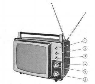
The 11" portable Philips 11LX520AT
|
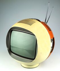
The Philips France TF1170 "Space Ball" TV. [Retro-futurism]
|
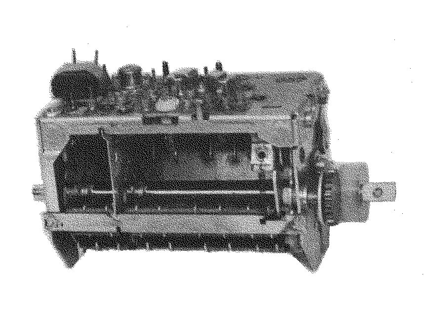
The Philips AT7652/80T transistor-based VHF tuner, and the last drum-type tuner. [Philips Elcoma Databook CM3, January 1969]
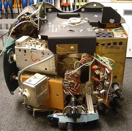
Interior view of the very cramped Philips TF1170 French ball-shaped "Space Age" TV, with left the V5T tuner. [TSF Forum]
|
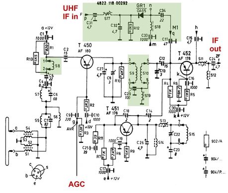
Circuit diagram of the Philips AT7652/80T VHF tuner. Circuit modifications compared with the AT7650/80T are highlighted in green. [Philips AT7652/80T Service Manual via Radiomuseum.org]
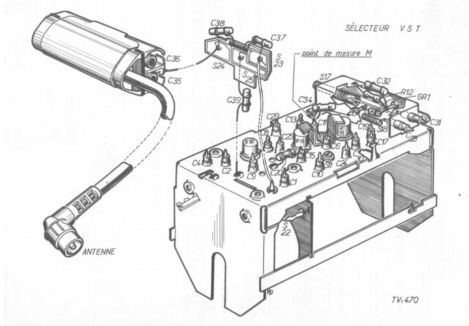
Nice drawing French-style of the Dreux version of the AT7652T. In French documentation this tuner is referred to as the V5T. [Philips Selecteur V5T Service Documentation via TSF Forum]
|
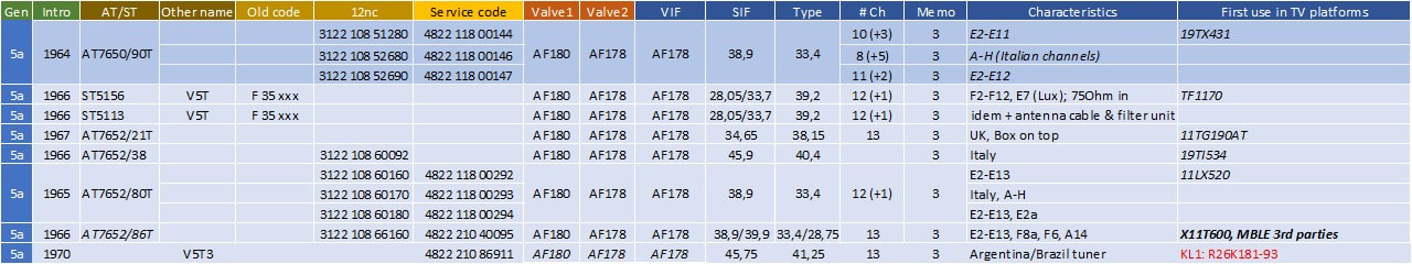
Overview of the Philips AT7650 family of transistor VHF tuners. These modules were specifically designed for portable TV sets (italic name), including one multi-standard (bold) and one CTV (red). Also note the change over in Italy from the original 45,9MHz IF (type suffix /38) to the CCIR standard (type suffix /39).
Pi1, the first VHF-UHF tuner, 1965
Especially the German television market, which was much more high end oriented, demanding advanced features and ease of control, drove the development of particularly the new push-button channel pre-set and selection concept. Germany had been the first to see wide deployment of the wired remote controls, additional stability control loops, fast start up etcetera, all features that were introduced from the end of the 1950s onwards. The same happened with the push-button control. Especially the UHF U5 (AT6380/80 or HA 362 58) in combination with the 4-button pre-set (HA 352 50) were used from end 1964 in almost all Krefeld sets, starting with the 23TD400 and 23TD500 families. And the 23TD514 and 515 even had 8-button pre-set using additionally the VHF V3a (AT7660/80 or HA 361 60). These were therefore the first Philips TV sets without a rotary tuner, and using push-button pre-set for both VHF and UHF. However, the total combination of VHF tuner, UHF tuner plus two mechanics was a massive assembly, and undoubtedly very costly because it was used in just two sets. Nevertheless it was a milestone, and the starting point of the next step in tuner development.
Mechanical drawing of the HA 353 50 combo VHF-UHF tuner with push-button channel pre-set and selection. On the left the UHF section, with top left the U5 tuner (HA 362 58). On the right the VHF section with the V3a (HA 361 60) valve tuner. The two mechanical sections are identical but mirrored. In the two smaller side views the construction of the translation-to-rotation mechanism is clearly visible. [Philips HA 353 50 Service Manual through Radiomuseum.org]
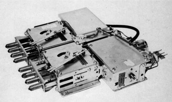
Picture of the HA 353 50 complete channel selection module. [Philips HA 353 50 Service Manual through Radiomuseum.org]
|
Surprisingly, the only good picture I could find of the HA 353 50 was inside a SABA set, the Schauinsland T2000 from 1967. [Marcel's TV Museum]
|
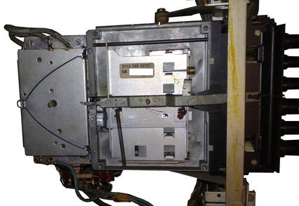
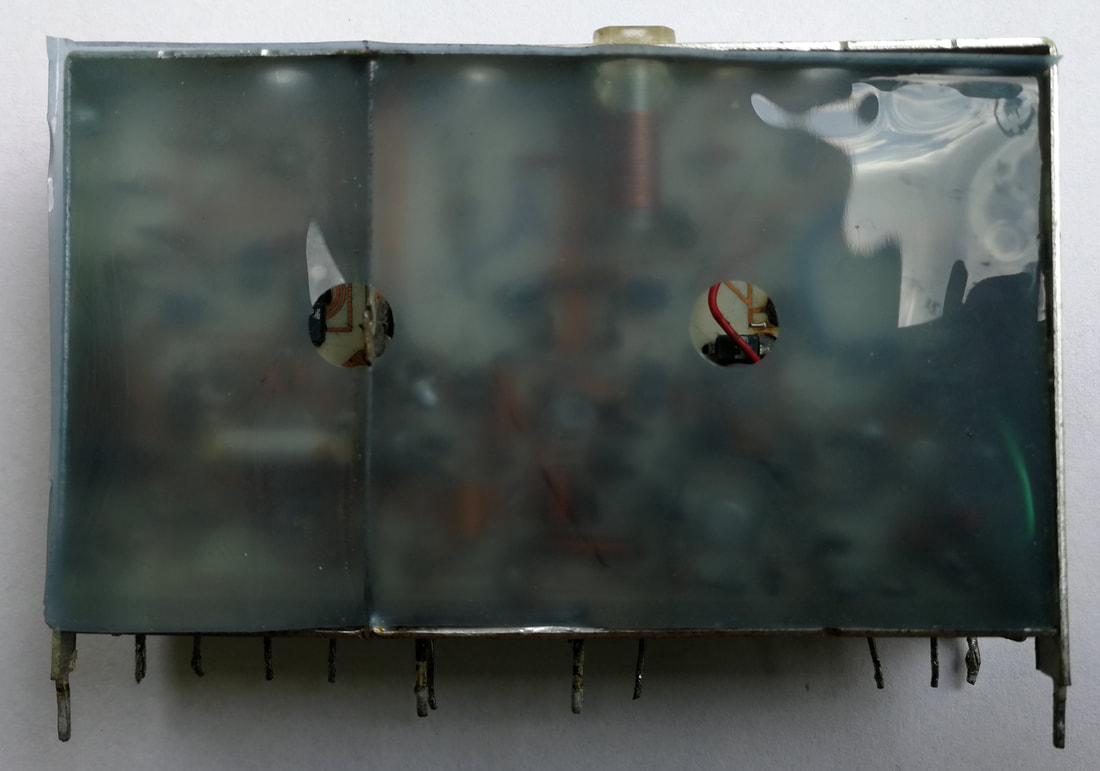
The Philips Pi1 VHF-UHF tuner. The two metal boxes are visible, separated by an open space that contans the band switching mechanism, of which the operating lever can be seen on the right. The white axis protruding through the top is the tuning inductor axis. [Philips Pi1 Service Manual]
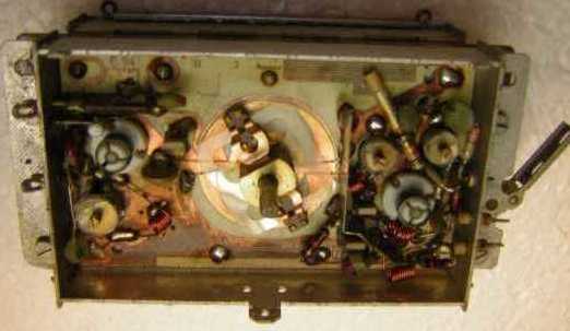
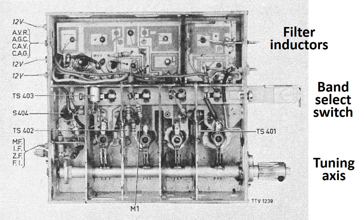
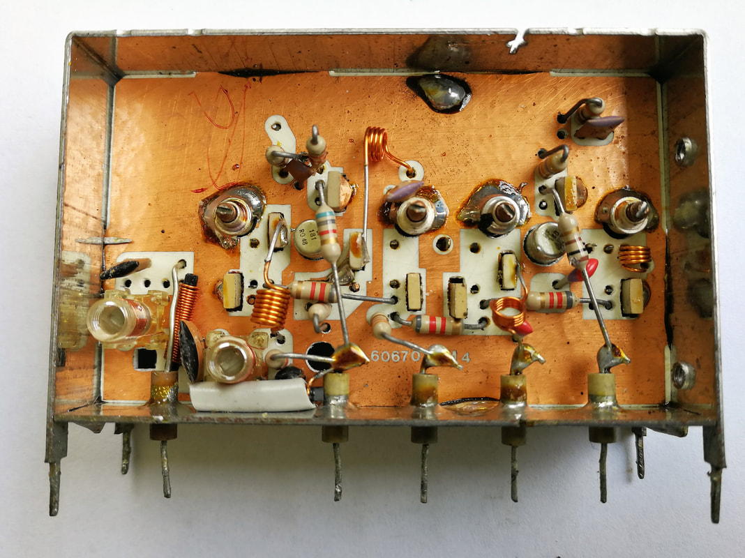
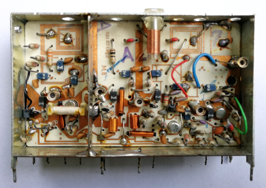
Interior view of the Philips Pi1 tuner. In the centre the rotating variable Lecher line tuning mechanism is clearly visible. This is the RF input box, with on the left side the input matching filters and the grey three-segment U/V1 switch. On the right side is the pre-amplifier around the AF239 transistor as well as the primary of the three BPF's. Because of the large central keep-out area of the tuning mechanism, especially the right side of the board is densely stuffed with components. On the righter outside we see the band changing lever. [Radiomuseum.org]
The Pi1, on the left, with its mechanical module as mounted in the 1967 D25K751 set. [Collsite]
|
Undoubtedly as a simplification and especially a cost reduction of the HA 353 50, the Krefeld tuner organization developed the Pi1, the first combined VHF-UHF tuner. This was a unique development, as far as I can see the very first time that a complete new tuner concept was developed outside Eindhoven. The reason for this remains unclear, but it seems most logical that the German Television organization was pushing for a cheaper combo tuner with push-button control, whereas the Dutch organization didn't consider this a priority. The Pi1, as the tuner was called - it is entirely unclear where this name comes from, having no relation with any other tuner naming - introduced a number of new characteristics and concepts:
|
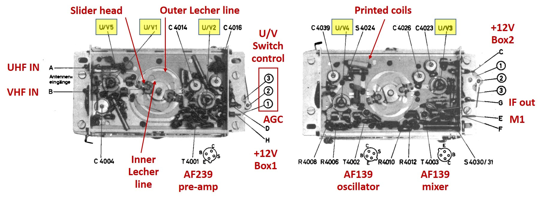
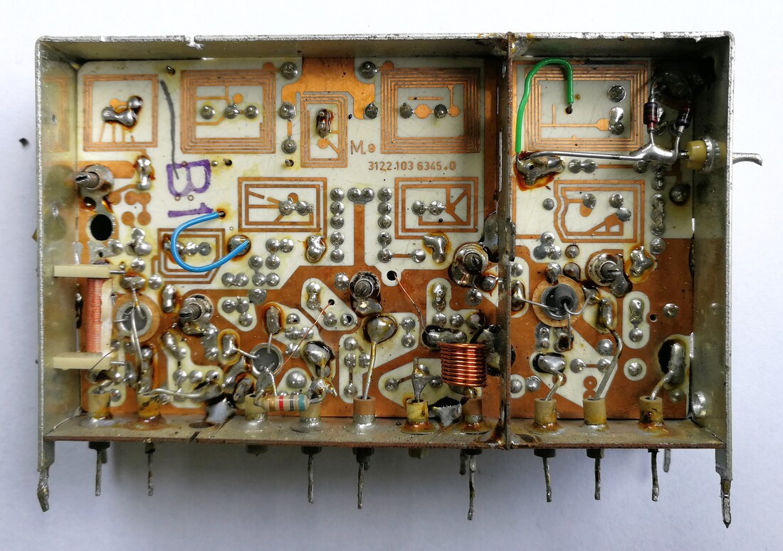
Interior views of the input box left and MO box right of the Pi1. Compare the left part with the picture above, which show the same section. [Philips Pi1 Service Manual]
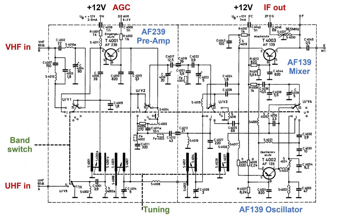
Circuit diagram of the Philips Pi1 VHF-UHF tuner [Philips Pi1 Service Manual]
|

Simplified circuit diagram of the Pi1 Bandpass filter, illustrating how the additional capacitors are switched parallel to the filter for each of the bands. Note that the three coupling lines of the BPF are the only electrical connections between the two boxes.
|
Although the circuit diagram looks very complex, effectively it is still the same basic concept as the previous VHF transistor tuners. The main difference was, as mentioned, the fact that tuning was done using variable inductors, where the same inductors were used for all bands. That meant that, starting from UHF with the lowest filter capacitance, for each successive band additional capacitors were added in parallel. This is best illustrated in the right figure showing the concept of the BPF. For UHF S4005-6-7- on the left form the primary section of the BPF together with C4014, which are top-coupled through S4008 (bridging from box 1 to 2) to the secondary of the BPF formed by S4012-3-4 and C4026. Ignoring all coupling capacitors, when switching to VHF-III the 4x larger capacitor C4016 is switched parallel to C4014, making it effectively 5x larger, while C4021 and 4023 are switched parallel to C4026 doing the same. For VHF-I similar switch-overs were implemented with again 65x bigger capacitances. (Remember that the frequency change goes with the square root of the capacitance change).
A typical Krefeld-built high-end TV using the Pi1 tuner assembly: the K6D Colour TV-chassis D25K760 Goya. The six channel select and preset buttons are clearly visible. [Radiomuseum-org]
|
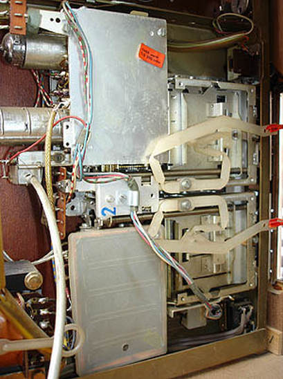
Interior view of the same D25K760 Goya, with on the left behind the black colour convergence control box the Pi1 tuner assembly. [Radiomuseum.org]
|
The Pi1 remains an oddity in the sense that is was used, as far as I
can see, only in German TV sets. All other countries used the AT7672
that will be discussed next. However, the Pi1 was not unsuccessful,
given that it was used from 1965 till 1969 in all mid to high end German
sets that used the push button channel selection. And yet it finally
seems to have been a one-off exercise, where a decidedly different tuner
was developed locally for one single country. We won't see this happen
again. So ultimately it probably was a case of "technically a good
solution, but politically such an adventure never again".

Overview of the first two efforts at integrated VHF-UHF push-button modules, the HA 353 50 and Pi1.
AT7672, the Eindhoven UV1 tuner, 1967
Well behind the Krefeld tuner development, also the central organization in Eindhoven started its development of an integrated transistorized VHF-UHF tuner, the AT7672 or UV1. (As we'll see in the remainder of this story, this was the last generations of tuners using the AT coding, which had been used since 1952). In contrast to the German concept of continuous inductive tuning with the step-wise addition of capacitors, the AT7672 used the inverse method, closer to the UHF tuners: continuous capacitive tuning with the step-wise addition of inductors. Like the UHF tuners it used four rotor capacitors for simultaneous tuning of input match, primary and secondary of the BPF an the oscillator tank circuit. One of the few elements it had in common with the Pi1, however, were the transistors used: the AF239 for the RF pre-amplifier, AF139 for the mixer and oscillator.
|
To start, the tuner was divided into a number of isolated chambers. All pre-filters for antenna matching and pre-filtering were housed in a small click-on module (blue in the right figure), which was often deleted in cheaper versions of the tuner. The red and purple sections formed the UHF tuner based on Lecher-line inductors, very much identical to a standard UHF-only tuner like the AT6380. Like in the Pi1 a complex multi-section band select switch connected additional inductors for VHF-III and -I reception. Most of these inductors were printed coils on a ceramic substrate.
With all these inter-connected inductors and the complex switch the circuit diagram became fairly complex and difficult to interpret. Therefore Philips already provided simplified circuit diagrams in its Service Manuals, which have been further combined and reduced in the right picture. In contrast to the Pi1, where the UHF inductors and capacitors remained an integral part of the VHF filters, in the UV1 the UHF Lecher-line inductors were only used in UHF mode, and bypassed in VHF. As a consequence the UV1 contained a remarkably high number of (printed) inductors. It seems that as a form of alignment tuning the filters could be connected at different points, see the dotted lines in below picture (e.g. coils h-i and q-r). 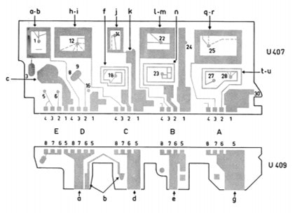
Lay-out of the printed coils on the ceramic substrate in the VHF filter section (yellow in the circuit diagram).
|
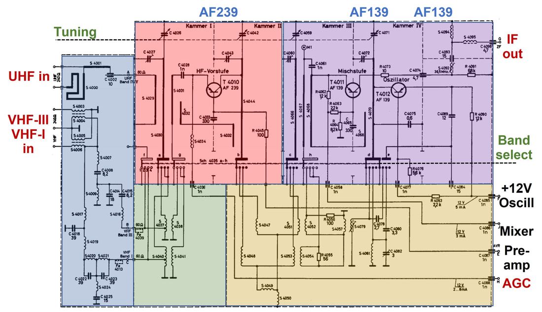
Circuit diagram of the Philips AT7672/90 (UV1) all-band tuner. Colours indicate the different compartments: blue the input filters, green the VHF input matching inductors, red the pre-amplifier and primary BPF, purple the secondary BPF and MO, and yellow the VHF inductors for BPF and oscillator. [Philips 4822 210 40079 Service Manual]
Simplified circuit diagrams of the Philips UV1 three-band tuner for the three different band settings. Unfortunately the top circuit diagram and these simplified circuits are from different versions of the service manuals and element coding are thus different (but nevertheless easily comparable). [Philips 2822 210 40079 Service Manual]
|
Picture of the Philips AT7672/01, the version with the click-on input pre-filter module on the right. The cover of the VHF coil section has been removed, exposing the ceramic substrate. [Philips 4822 210 40079 Service Manual]
|
Interior view of the Philips AT7672/90, the standard version without the pre-filter. At the bottom the UHF tuner section with the variable capacitors, above the VHF coil section. In the centre the linear band select switch is visible. [Philips 4822 210 40079 Service Manual]
|
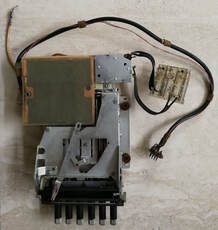
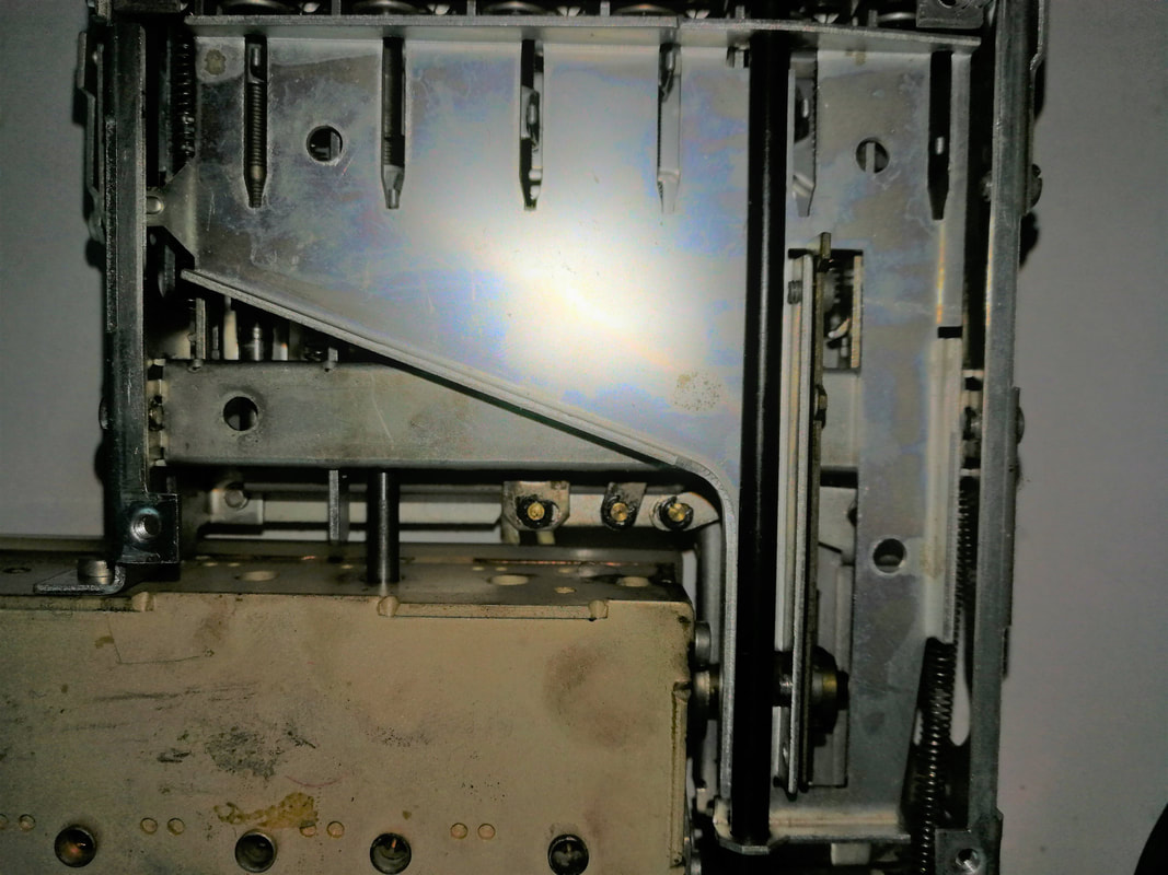
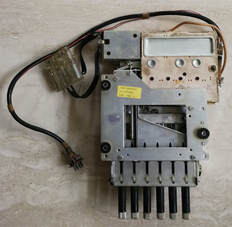
Three pictures of the AT7674/90, a special version of the UV1 with an additional VHF-Ia band, the purpose of which is not clear yet, but most probably to allow an external RF device (early VCR, satellite or remodulator units??) to be connected. The name seems therefore to have been UVV1, see the printed coil ceramic board in the leftmost picture. The housing of the UV1 seems to have been of moulded and then baked ceramic powder, possibly containing metal particles for shielding. On the back side four openings were covered with tightly fitting aluminium covers. The right picture shows the backside of the printed coil board with the cover removed. In the central picture part of the tuning and pre-set mechanism can be seen, where the dented racks rotated the variable capacitor shaft. [Pieter Hooijmans collection via Ite Weide]
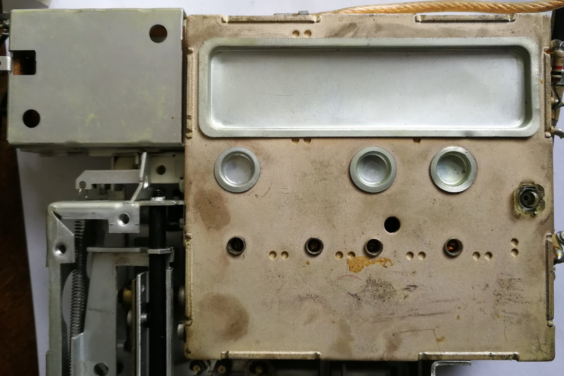
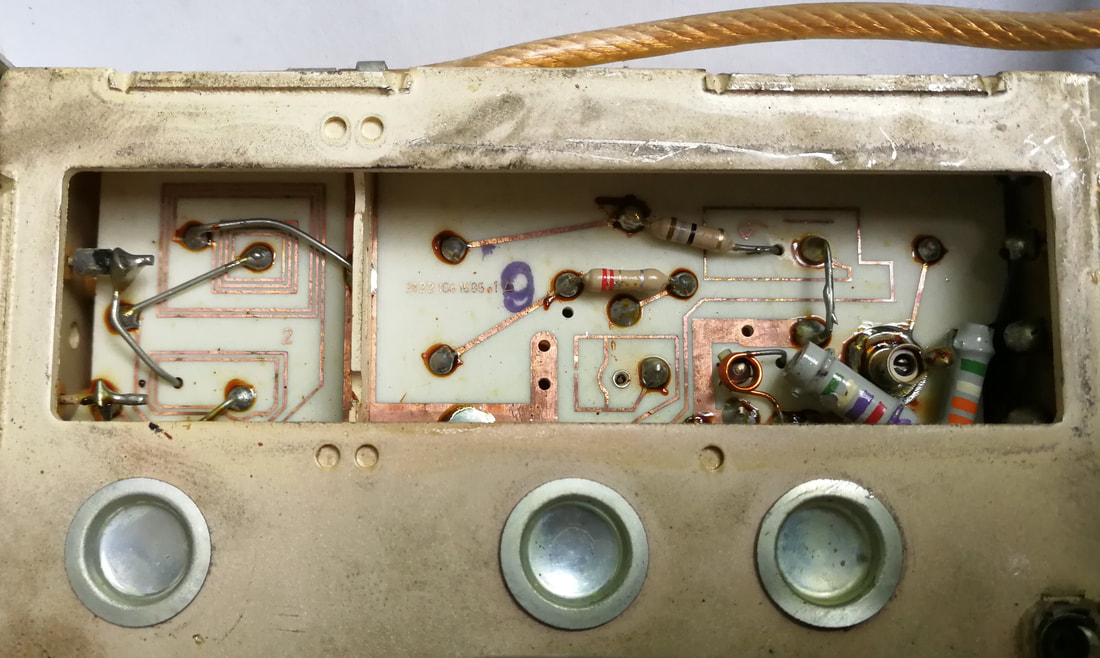
The above developments of the UV1 were ultimately targeted at only one single objective: a tuner allowing identical pre-set button channel pre-set and selection for all channels and without band pre-allocation of the buttons. In other words, each of the (normally 6) push-buttons could be used for either VHF or UHF. This was now possible! The consequence was, however, that the mechanics became even more complex because when pre-setting a channel not only the tuning setting needed be stored, but also the band selection. So the already complex mechanical module of the AT6380 was extended with band selection memorization, where the original core remained unchanged: an upper and lower slider that took a horizontal position determined by the pre-setting spindle, which jointly rotated the tuner axis. The band selection was done with a 3-position lever (at the blue arrow below) that was operated by the push-buttons and in turn moved the band switch on the tuner, and, through bracket G rotated the band indicator drum (4) on the front panel. All in all an amazingly complex (and thus undoubtedly expensive) mechanical module. Although it seems to have given quite some service trouble due to dried out grease of the spindles - which was annoying but easily repaired - the module was very successfully deployed in many sets for a number of years, until really electronic tuning became possible with varicap diodes.
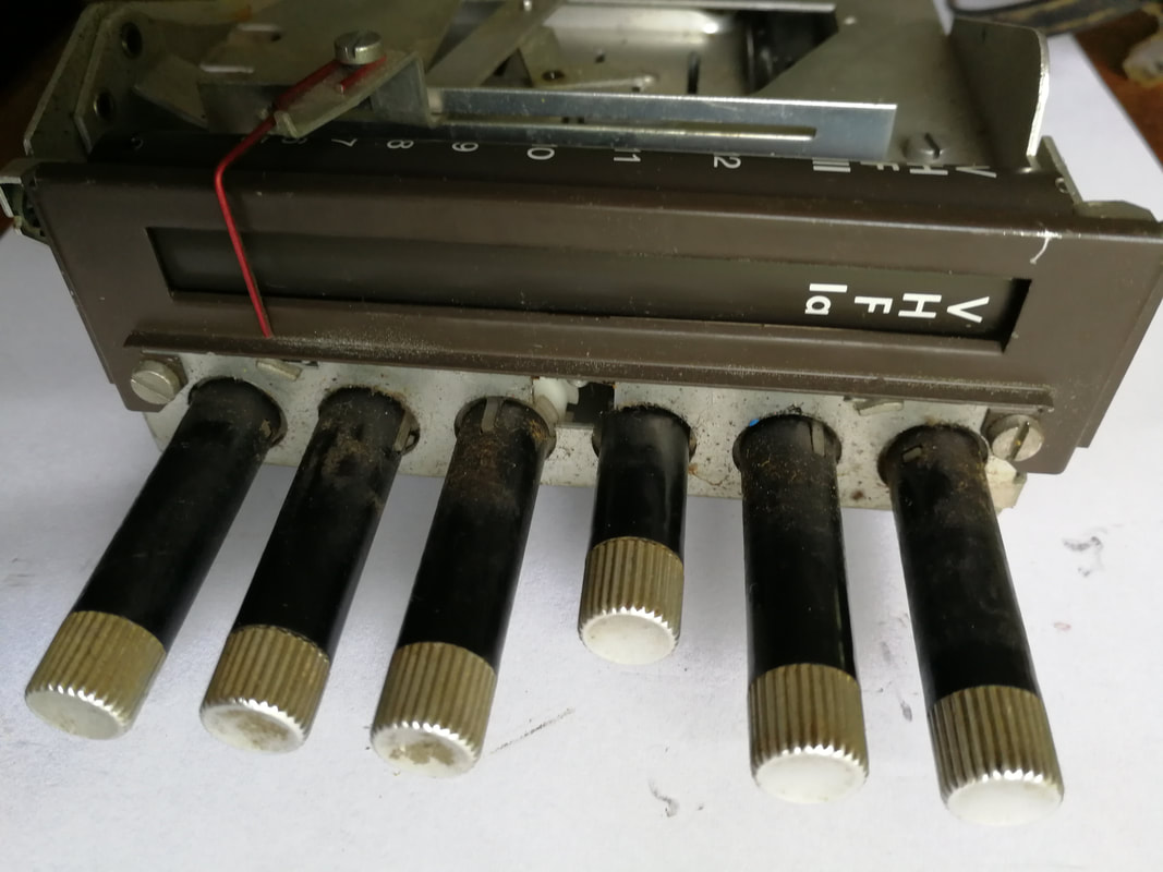
The 6-channel pre-set and channel+band selection module as used in combination with the AT7672 UV1 tuner. [Philips 4822 276 60045 Service Manual]
|
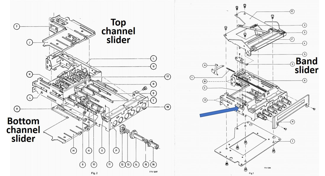
Exploded view of the 6-channel pre-set button module. Note the complexity increase compared to the previous UHF-only module. At the blue arrow the 3-position band selection lever that activates the band indicator drum. [Philips 4822 276 60045 Service Manual]
|
Top view of the complete AT7673/90 assembly, with upper left the plastic cover of the UV1 tuner. [All pictures Ite Weide collection]
|
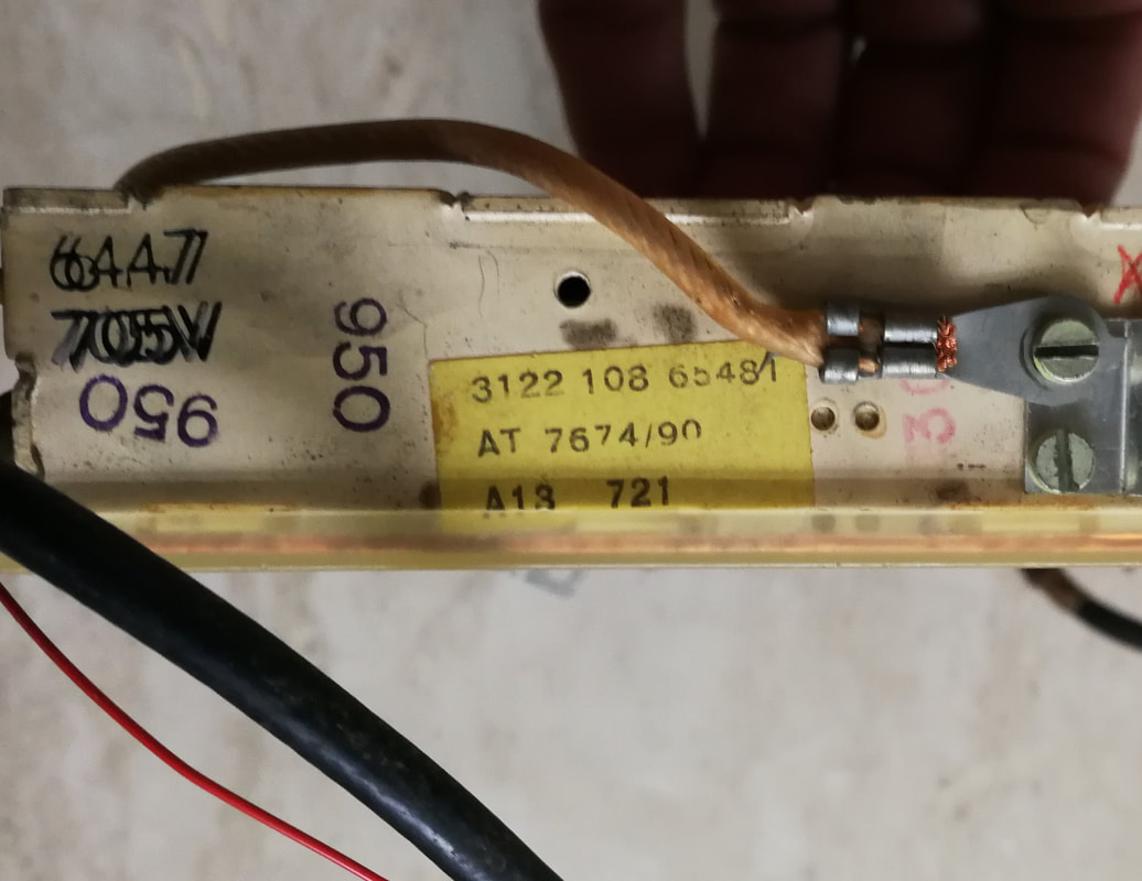
The AT7674/90 version of the UV1 tuner. Produced in Eindhoven (A) in 1967 week 21.
|
The bottom side of the assembly, with the trapezium-shaped bottom slider. Each channel button has a pre-set pin that pushes the slider through the slits in the bottom.
|
Bottom view of the complete AT7673/90 tuner with removed mounting plate, where the type number probably refers to the total assembly.
|
The mechanism where the band selection lever rotates the gear wheel of the band indicator drum.
|
This tuner had 4 band choices, with the VHF-Ia band as shown. Its exact coverage is unclear, but could be related to a VHF VCR input.
|
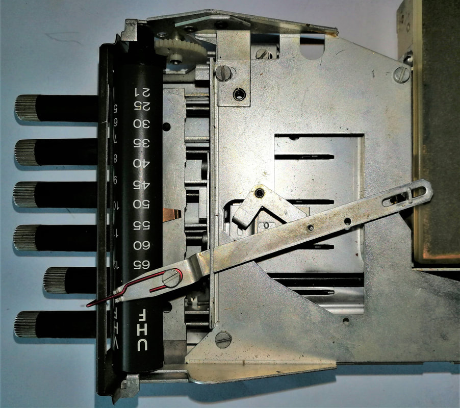
Illustration of the channel indicator mechanism. In this picture, for the highest channel, the top slider is fully moved to the left (note the position of the slits).
|
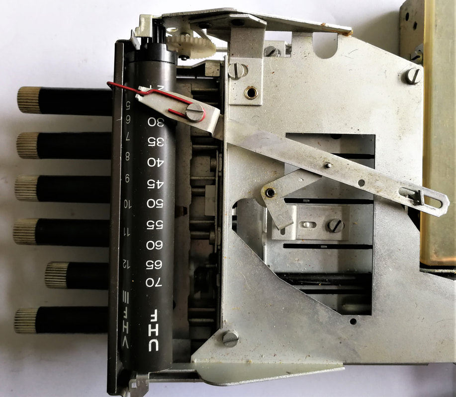
The same mechanism for the lowest channel in the band, with the top slider fully moved to the right (compare the position of the slits).
|
Detailed view of the bottom slider with its pre-setting slits. The slider moves along the black guiding rod on the right. At the bottom right the arm of the tuner band selection switch.
|
The Philips AT7672/01 with input pre-filter module and 6-channel push button pre-set module in the X23T632 from early 1967. [Marcel's TV Museum]
|
The Philips AT7680/90 three-band tuner with single button band selection and tuning, but no pre-set. [Philips Elcoma Data Book CM3, January 1969]
As noted the 6-channel pre-set module must have been pretty expensive, while furthermore the combined tuner-mechanics assembly was fairly deep, as shown on the left picture. For the more compact 9, 11 and even 20inch sets this was too big, and consequently a more compact but less advanced assembly was introduced as the AT7680 tuner plus tuning mechanics and indicator. Separate concentric knobs took care of band switching, crude and fine tuning. Although I've found actual use of these tuners in a few Dutch and German portable sets, they were never as present as the 6-channel pre-set module.
One other special tuner within the family was the French version of the UV1 (coded F 35 183), which was a 4-band version, covering VHF (40,25-55,4MHz), VHF-III odd channels (173,5-225,25MHz), VHF-III even channels (160,75-217,25MHz) as well as UHF (470-865MHz). Since furthermore it required selection of the standard (819 or 625 lines) and the bandwidth (819-large in France, 819-narrow in Belgium/Luxembourg), in practice this meant each of the 6 buttons was pre-set to a standard. |
A typical TV chassis using the UV1 tuner with its six pre-set channels. These were used in the 1967 T600 family, like this X23T611, up to the first T700 in 1970. [Marcels TV Museum]
|
Interior view of the Philips X23T611. Lower left the UV1 tuner assembly. Other than that a single PCB with still 11 valves. [Marcels TV Museum]
|
However, besides all these tuner-specific developments, the AT7672 was special for an entirely different historical feat: it was introduced together with the first volume Philips colour TV! So the very first sets using it were of the K6 platform, launched in 1966 with the X25K120 and 130. Only after this first step the AT7672 was deployed in non-colour high-end sets. The same happened in Germany in 1967, the D25K760 Goya, and the UK, with the G25K500 colour sets. In France colour was also introduced the same years, first with two separate older generation tuners, but the UV1 was then also quickly adopted. The colour era had (finally) started!
Overview of the Philips AT7672 and 7680 VHF-UHF three-band transistor tuners. Note that the AT7672 code was for the tuner only, while the AT7680 covered both the tuner and the selection mechanics. Also note the variation in transistors used, where ON15x were codes of non-third party released transistors. As to the TV platforms overview: red = colour, bold = multi-norm, italics = portable.
The introduction of colour television
This section has been substantially shorted compared to the original text.
Although, as we will see, the introduction of colour TV didn't have major impact on the TV tuner, overall it has been a major innovation step in TV development, and thus merits some closer attention. Because there are many places where details about the principles of colour TV can be found, I will concentrate mainly on the development history of the technology. Colour television broadcast was definitely no European invention, it started as early as 1953 in the US, when the National Television System Committee (NTSC) defined a 2nd standard carrying the same name, this time for colour transmission and reception. (The first 1941 NTSC standard defined black-and-white TV reception). The first nation-wide colour broadcast in the US was January 1, 1954, but after that things went extremely slow. Sets were very expensive, broadcast in colour minimal (only NBC, with its mother company RCA providing the sets, did transmit some of its programs in colour), and the US thus effectively remained B&W like Europe. As late as 1964 only 3% of the TV sets sold in the US was a colour TV!
Although, as we will see, the introduction of colour TV didn't have major impact on the TV tuner, overall it has been a major innovation step in TV development, and thus merits some closer attention. Because there are many places where details about the principles of colour TV can be found, I will concentrate mainly on the development history of the technology. Colour television broadcast was definitely no European invention, it started as early as 1953 in the US, when the National Television System Committee (NTSC) defined a 2nd standard carrying the same name, this time for colour transmission and reception. (The first 1941 NTSC standard defined black-and-white TV reception). The first nation-wide colour broadcast in the US was January 1, 1954, but after that things went extremely slow. Sets were very expensive, broadcast in colour minimal (only NBC, with its mother company RCA providing the sets, did transmit some of its programs in colour), and the US thus effectively remained B&W like Europe. As late as 1964 only 3% of the TV sets sold in the US was a colour TV!
All colour standards, starting with NTSC, use a sub-carrier to encode the colour (C, consisting of the elements Red (R), Blue (B) and Green (G)) information which is added to the standard black-white intensity (Y) information (which allows backward compatibility to the older sets by simply ignoring the colour information). For NTSC this was 3.579545MHz, with the colour modulated using quadrature AM on two orthogonal but suppressed carriers at this frequency. The drawback of NTSC was that the colour was defined by the absolute phase of the two quadrature carriers, which meant that in case of serious phase distortion in the transmission path colour hue errors became very visible. In Europe this lead to two optimizing developments, the first being SECAM (Séquentiel Couleur à Mémoire, or Sequential Colour with Memory) in France, developed by a group under Henri de France at Thomson-CFT. This system FM-coded the orthogonal U=B-Y and V=R-Y colour information on two successive lines, which were combined by delaying one with a delay line. This introduced the principle that colour information had half the vertical resolution of the intensity signal. SECAM-E for 819-lines was available for testing by the end of the 1950's, and the de Gaulle French government started an aggressive sales campaign to get SECAM adopted as the European colour standard.
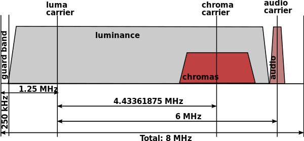
The composite frequency spectrum of a colour CCIR-G signal with PAL colour encoding. For CCIR-B the picture is almost identical with a channel bandwidth of 7MHz instead of 8. The bandwidth of the colour AM modulation is roughly +/-1MHz. [Wikipedia]
|
Philips however, and probably also the majority of the German and British TV set makers and authorities, did not like this idea. Philips had chosen for NTSC, almost certainly to come to a single standard for its European and growing North American sales (which included Canada!). Then two things happened: first the European CCIR decided to base the future colour standard on 625 lines, secondly the invention in 1962 of the PAL (Phase Alternating Lines) by the group of Walter Bruch at Telefunken in Hannover, Germany. The first development forced the French to re-develop SECAM for 625 lines, which they proposed to the CCIR in 1961. PAL was essentially a mix of NTSC (all colour information transmitted each line in AM) and SECAM (different colour information on alternating lines, combined using a delay line) but now transmitted the same colour information on successive lines with inverted V=R-Y phase. Like SECAM this required a 1-line delay line and reduced the vertical colour resolution by two. For PAL (and SECAM for 625 lines) the colour carrier was chosen as 567,5 (the number of colour clock cycles per line) /2 (because vertical interlacing) * 15.625 (the line frequency) + 25 (offset to avoid interference) = 4,43361875 MHz, placing it at the upper end of the video band, roughly 1MHz below the sound carrier. (For SECAM-L the colour carriers were at 4,406 (R-Y) and 4,25MHz (B-Y)). PAL was formally proposed as the new standard in 1962.
|
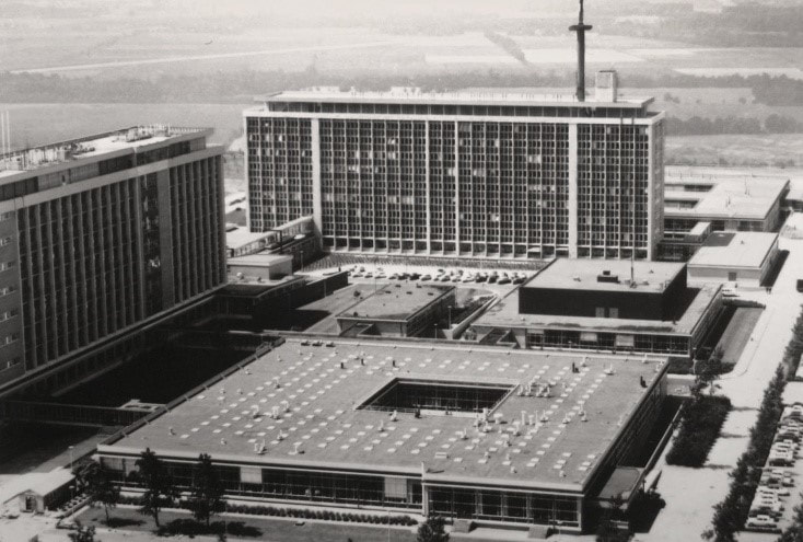
The Philips Natuurkundig Laboratorium Research Labs in Waalre early 1960s after the Research organization transferred there from the much smaller buildings on the Strijp-S complex in central Eindhoven. On the left the main building WB, farthest ahead building WY with on its roof the experimental colour TV transmit tower. The low building in front is WD with the mechanical workshops, and between that and WY, with the raised black roof, is WO containing the studio for the experimental TV programs. [NatLab site Henk Hagenbeuk]
Interior view of the prototype, non-commercial Philips K4 NTSC colour TV 21KX100 from 1964. Originally the upper cabinet, which could be detached from the lower half, only contained the large picture tube and the tuner modules on the left. Originally the picture tube was the GE 21FBP22, later apparently replaced by the new Philips AX53-14 tube. In the lower cabinet the old style single chassis, all valve based. In 1966 most of these sets were modified for PAL using the vertical, all transistor PCB with the red delay line. [Pieter Hooijmans via Taco Vonk]
|
The tuner modules of the K4: on the right the AT7639/90R VHF tuner with PCC189 en PCF86, left the U5 tuner. In the original set these were still valve based AT6343 (790MHz) and AT6352 (860MHz). Above the tuner blocks an EM87 tuning magic eye, the only time this was applied in a TV! [Pieter Hooijmans via Taco Vonk]
|
On the studio side of the chain it must be noted that the first Plumbicon picture scanning tubes were used, which would become the de facto world standard for this function, and a multi-decade cash cow for Philips, both in sales and patent licensing income.
Then Président de Gaulle made one of its characteristic moves and in March 1965 convinced the Soviet Union and its Eastern European satellites to adopt SECAM on top of their CCIR-D/K standards, based on the technical argument of better long distance colour performance. This forced Philips to make a choice, and it formally dropped its support for NTSC, joined the German and British party in support of PAL. The superior colour performance of PAL as opposed to NTSC must surely have played a role in this. As a result the company now needed to develop a PAL colour receiver, while the experimental transmission also switched to PAL, probably using K5 experimental sets. However, just like had happened in 1948 with the switch from 567 to 625 lines, the sets originally designed for the old system were converted to the new standard. Many of the K4 21KX100 NTSC sets were thus converted to PAL reception, receiving a new colour processing PCB including the 64us delay line (from Telefunken). (It is suggested that the now unusable NTSC sets were sold in Canada, an NTSC market. However, given that most known surviving sets are converted for PAL this seems unlikely. The confusion probably comes from the fact that one of the surviving sets was on display in a Canadian museum).
Towards 1965 it became clear that, like had happened 15 years earlier for black-and-white TV, no consensus on a single European standard could be reached, although in this case the number of dissidents had been reduced to only one: France stuck with its SECAM-L system. All other Western European countries opted for PAL-B/G or PAL-I (UHF-only in the UK). From that moment onwards things went faster, and on August 25, 1967 Bundeskanzler Willy Brandt launched regular colour transmission in Germany and Europe from the Internationale Funkausstellung (IFA) in Berlin. The Netherlands followed closely on September 21 during the similar Firato electronics show in Amsterdam and BBC2 on December 2. France started colour transmissions on October 1 on its 2nd channel on VHF, although it would take 15 years before the 819-lines TF1 channel was also nation-wide converted to 625-lines colour.
By this time Philips had launched its first commercial colour TV sets based on the K6 chassis, with the X25K120 in the Netherlands, G25K500 in the UK and D25K760 in Germany, other regional derivatives following soon. These all used the AT7672 integrated VHF-UHF tuner with 6-button channel pre-set, which brings us back to where we were in the previous section.
The first production Colour TV by Philips, the K6 chassis. This is the X25K123. Note the complete technology change from the K4 prototype. 90% of the electronics were still valve-based. [Marcels TV Museum]
|
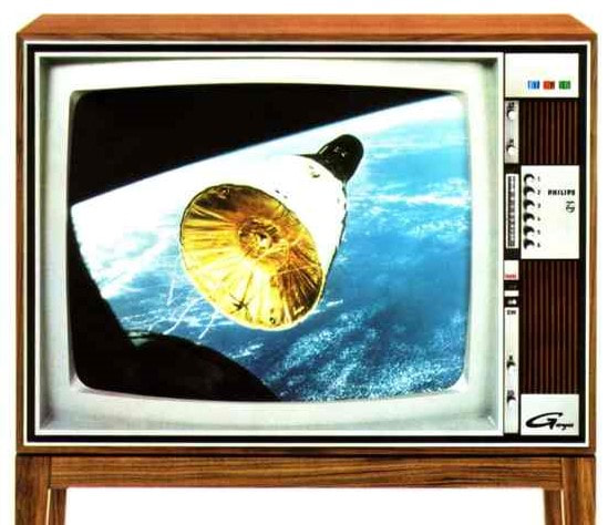
A Krefeld version of the 1965 K6 colour chassis, the D25K760 Goya, showing a nice picture of a Gemini manned spacecraft, which were flying those days as preparation for the Apollo project.
|
Varicap diodes, 1966
|
An innovation that was to have a much bigger impact on tuner design than the introduction of colour TV was the varicap diode, or varactor, essentially a voltage-dependent variable capacitor. Progress in transistor fabrication made it possible to make accurate PN-junctions in silicon, which were used in reverse bias, thus depleting the area around the junction from charge carriers. The junction thus becomes a capacitor where the plates are determined by the size of the junction (A) and the plate distance by the depth of the depletion zone (d). When the reverse bias increases the depletion zone becomes deeper and the capacitance which proportional to A/d thus reduces. The voltage-to-capacitance relation is given by the formula in the picture. The factor m is called the grading coefficient, and is determined by the doping levels and vertical structure of the junction. In first generation shallow junction varicaps m was mostly 0,33.
|
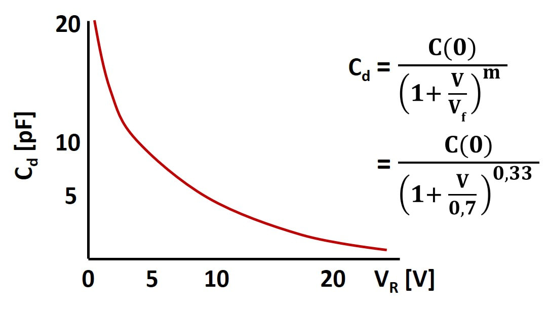
The typical varicap capacitance-to-voltage curve and the associated formula. Vf is the forward voltage of the diode, m is the technology-determined grading coefficient. The curve shown is roughly the BB105 curve, the varicap used in the Philips tuners.
|
The varicaps that were first used in the Philips tuners were the BB105A and BB105G, both having a maximum reverse voltage of 25V. They were almost certainly binned or sub-optimized special versions of the generic common type BB105, which had more relaxed specs. The BB105A had a minimal C(0)/C(25) of 4,5 and was thus used in UHF where the relative tuning range is largest. The BB105G with a minimal ratio of 4,0 was used in VHF bands I and III. Compared to the older metal can transistors and glass encapsulated diodes also quite some package innovation had been implemented. The diode's anode was wire-bonded with gold wire to one lead frame contact, while the metallized back side of the cathode was connected to the other lead frame contact. The diodes were one of the first to be plastic over-moulded, making their packages much more compact and, especially important, with lower parasitics.
The first commercial tuner varicaps were probably released around 1966, and the first tuners using them were released in 1968, the KD1. However, the introduction of varicaps, although highly desired for electronic tuning, came at a price: their initially high series resistance meant that the tuned circuits suffered a serious Quality-factor (Q) reduction, resulting in less reliable oscillators (tank circuits) or wider filters, resulting in more noise and adjacent channel interference. It would take a few generations and almost 15 years to get the selectivity back to where it had been with mechanically tuned circuits!
The first commercial tuner varicaps were probably released around 1966, and the first tuners using them were released in 1968, the KD1. However, the introduction of varicaps, although highly desired for electronic tuning, came at a price: their initially high series resistance meant that the tuned circuits suffered a serious Quality-factor (Q) reduction, resulting in less reliable oscillators (tank circuits) or wider filters, resulting in more noise and adjacent channel interference. It would take a few generations and almost 15 years to get the selectivity back to where it had been with mechanically tuned circuits!
Philips Tuner new naming convention
This section has been substantially shortened compared to the original text.
The tuners didn't escape from a new naming. Since 1952 the official naming of tuner modules had been AT75xx or AT76xx for VHF tuners and AT63xx for UHF, and this system ran well into 1968. As we've seen earlier, AT referred to electronic modules (A) for television (T) and not exclusively to tuners; this category also included e.g. speakers and line output transformers. By 1965 we see a new, still parallel new naming coming up: V3, V5 for VHF tuners, U5 for UHF, UV1 for the first combo-tuner. Although I haven't been able to confirm this, it seems that this coding of tuner generations was in fact the one used internally, starting with the V0 in 1951. And in parallel again the German organization came with even more creative "local" names: Pi1, KD1, KD2. These developments made that the AT7682 UV1 tuner was the last to use the AT-code till 1968. At least in Germany the AT-system, which was probably running out of free slots, was replaced by the 12ET5630 codes. Where 12 probably referred to the German country code and ET replaced AT. This system was also used for other TV sub-assemblies in Krefeld sets and was the official name of the VD1 and UD1 as used in the external customer documentation data books, although short-lived and for these two tuners only.
The tuners didn't escape from a new naming. Since 1952 the official naming of tuner modules had been AT75xx or AT76xx for VHF tuners and AT63xx for UHF, and this system ran well into 1968. As we've seen earlier, AT referred to electronic modules (A) for television (T) and not exclusively to tuners; this category also included e.g. speakers and line output transformers. By 1965 we see a new, still parallel new naming coming up: V3, V5 for VHF tuners, U5 for UHF, UV1 for the first combo-tuner. Although I haven't been able to confirm this, it seems that this coding of tuner generations was in fact the one used internally, starting with the V0 in 1951. And in parallel again the German organization came with even more creative "local" names: Pi1, KD1, KD2. These developments made that the AT7682 UV1 tuner was the last to use the AT-code till 1968. At least in Germany the AT-system, which was probably running out of free slots, was replaced by the 12ET5630 codes. Where 12 probably referred to the German country code and ET replaced AT. This system was also used for other TV sub-assemblies in Krefeld sets and was the official name of the VD1 and UD1 as used in the external customer documentation data books, although short-lived and for these two tuners only.
KD1 and KD2, the first varicap tuners, 1968
|
As had happened with the introduction of the transistor tuner, also with varicaps the German tuner organization came first with a local design not derived from an Eindhoven platform. The tuner was called KD1, with KD almost certainly for "Kombi Deutschland", since it was a combined VHF and UHF tuner. However, the possibility of electronic tuning - no longer requiring the mechanical constructions with variable capacitors or inductors - and the decreasing prices of semiconductor components allowed a more liberal use of these, and no longer the need for complicated constructions around band switches as in the previous generation. As a result the KD1 was formed from two completely separated VHF and UHF tuners with the same form factor, that were mounted inside a single tin can cover for PCB mounting. Although I haven't seen an opened KD-tuner so far, on the inside it seems to have had two separate PCBs (one each for VHF and UHF) mounted on a common base plate. This meant that there was no sharing of transistors between bands, and the KD1 thus had a then record semiconductor content of 5 transistors, 6 varicaps and 8 switching diodes, a major increase from the 3 transistors of the previous generations.
|
The Philips KD1, the first varicap tuner. [Philips KD1 4812 210 47004 Service Manual]
|
|
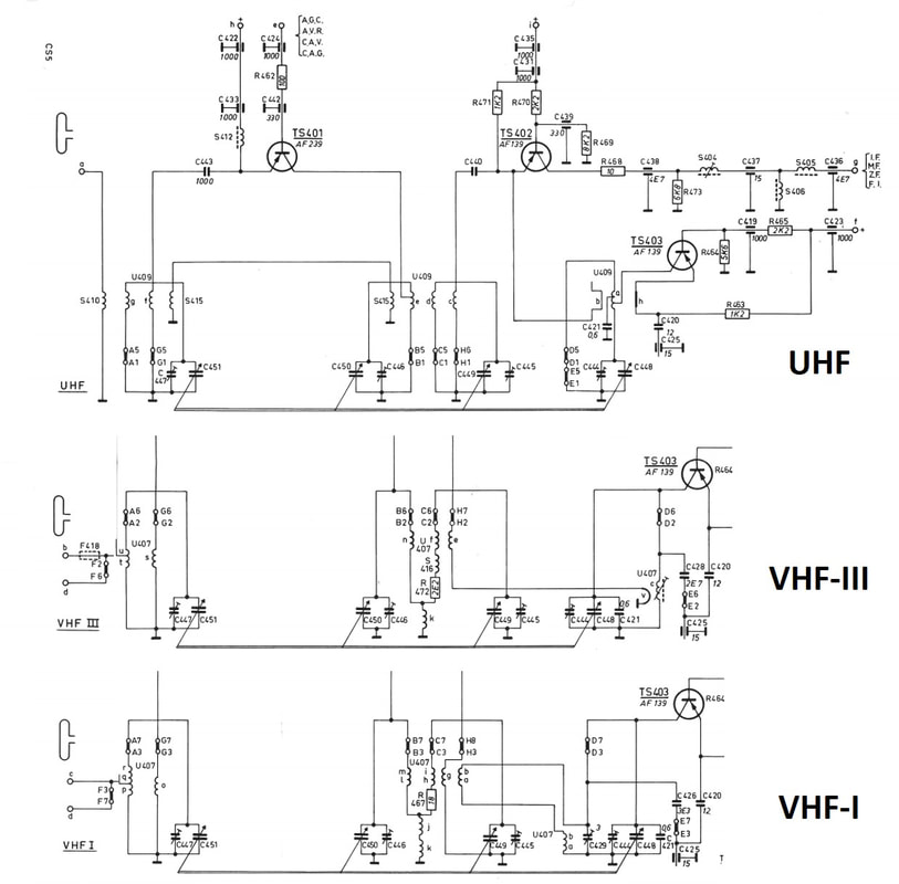
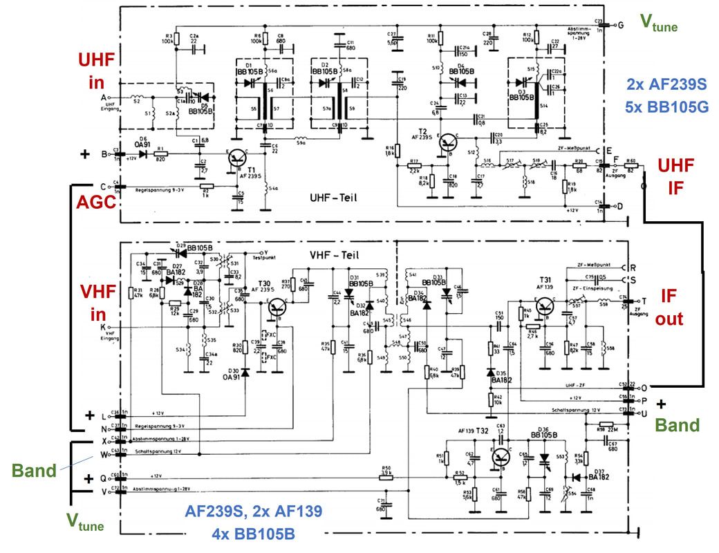
With the varicaps the circuit diagrams became much more straightforward again, especially for UHF. So if we take the earliest AT6370 transistor tuner and replace the mechanical variable capacitors with varicaps, we're already very close. Some remarks as to the UHF tuner:
|
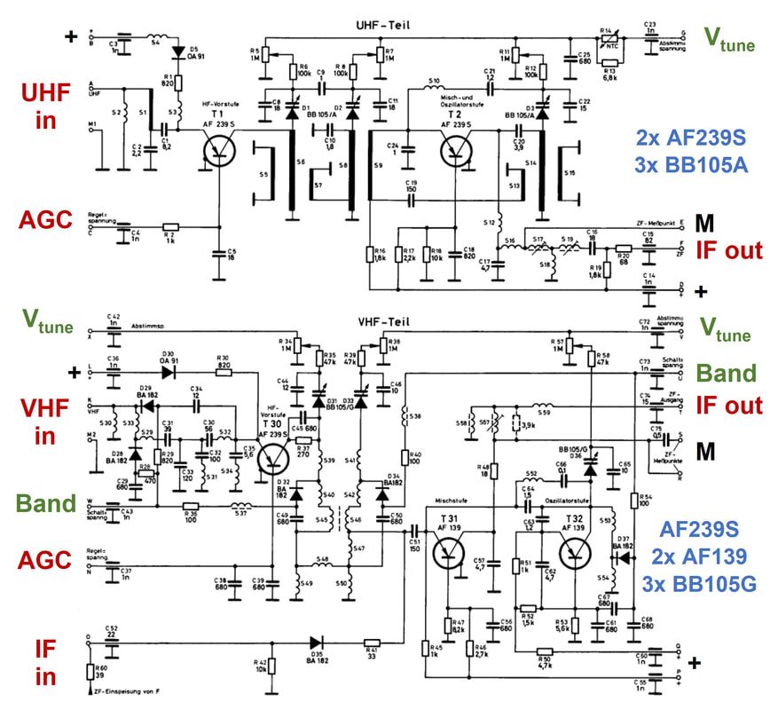
Circuit diagram of the Philips KD1 or 12ET5630 varicap VHF-UHF tuner. [Philips 4812 210 47004 KD1 Service Manual through Radiomuseum.org]
|
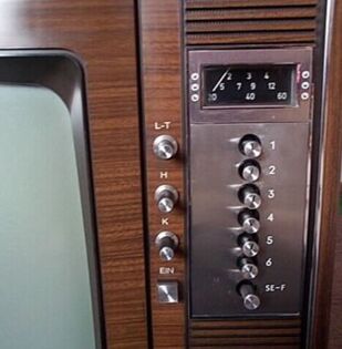
The channel selection front panel of the K6N D25K860 Goya Luxus Color Automatiek. The analogue volt meter tuning voltage indicator is visible above the selection push buttons.[Radiomuseum.org]
|
The KD1 was introduced in the German Philips K6N platform in 1968, an upgrade of the first K6 colour platform, replacing the Pi1 and its complex mechanical 6-button pre-set module. Nevertheless it was just a bit too early for real electronic tuning, so the K6N still used a push-button module for channel selection, albeit much simpler than the complex modules of the Pi1 and UV1. The module is shown below. The 6 channel selection buttons were now only for selecting their individual potentiometer with the pre-set channel tuning voltage (the green signal path shown for channel 6) and the band selection. The 7th button is used for pre-setting the channel voltages and for switching between front panel channel selection of via the (wired) remote control. In VHF mode the red line supplies the VHF pre-stage (L) and oscillator (Q) with 12V. In UHF mode the orange line supplies the UHF module, but note that the VHF mixer annex UHF IF amplifier is always supplied via pin P. In VHF-III the blue line activates the Band Switching lines, while for reasons not entirely clear the same is done in UHF mode. Because there was no longer the need for the complex mechanical memories and the associated mechanical transfer to the tuning axis and band switch, the module was considerably simpler and smaller. This allowed room for two new features, visible on below diagram: 1. when a channel was selected there was a small neon light near the push button for channel indication, and 2. the tuning voltage was indicated on a front panel analogue volt meter, probably as a rough channel/frequency indicator.
|
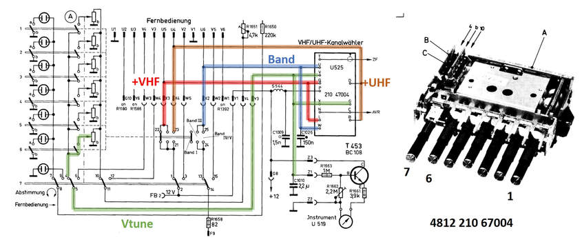
Circuit diagram of the pre-set module and KD1/12ET5630 tuner assembly, with a picture of the push button unit on the right. Note that the TV could also be connected to a wired remote control (Fernbedienung), which contained 4 channel pre-set and selection buttons identical to the ones on the front panel. On the left of the diagram are the 7 small neon lights that would switch on next to the selected channel button. [Philips D25K860 Service Manual through Radiomuseum.org]
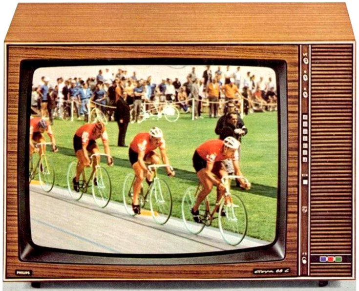
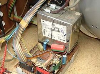
The KD2 tuner was used for German K7 platform (K7D from 1968, K7N 1969) and the first K8D in 1970. Shown here is the K7N D26K964 Goya Luxus 66. [RadioMuseum.org]
|
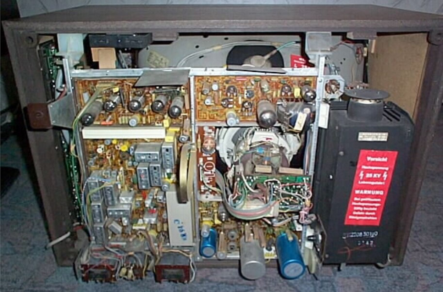
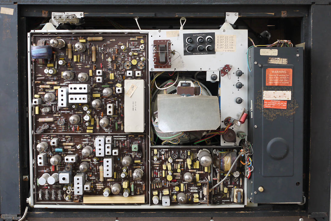
Interior view of the Philips D26K964 Goya Luxus 66. Although the IF panel lower left is fully transitorised, the large signal part still contains 13 valves from the 200, 500 and 800 generations. The KD2 is mounted on the bottom of the cabinet and not visible on this picture. [Radiomuseum.org]
|
|
The KD1 didn't live long and was quickly replaced by the KD2 (or 12ET5631), which essentially omitted the individual potentiometers for all varicaps. But for the same reason that it had been introduced in earlier generations, also the KD2 performance required an upgrade by the introduction of a tuned input matching filter. This was implemented in the "final" KD2, which was the version that was used very successfully for two successive colour TV generations: the K7D (launched in 1968) and the K8D (from 1970). On these chassis the channel selection interface was further improved. It no longer required the heavy mechanical push button assembly of the KD1, but used light PCB-mounted switches. And as a next step, in the K8D the KD2 tuner module finally moved onto the small signal panel.
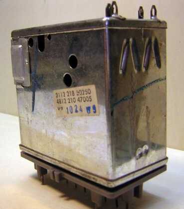
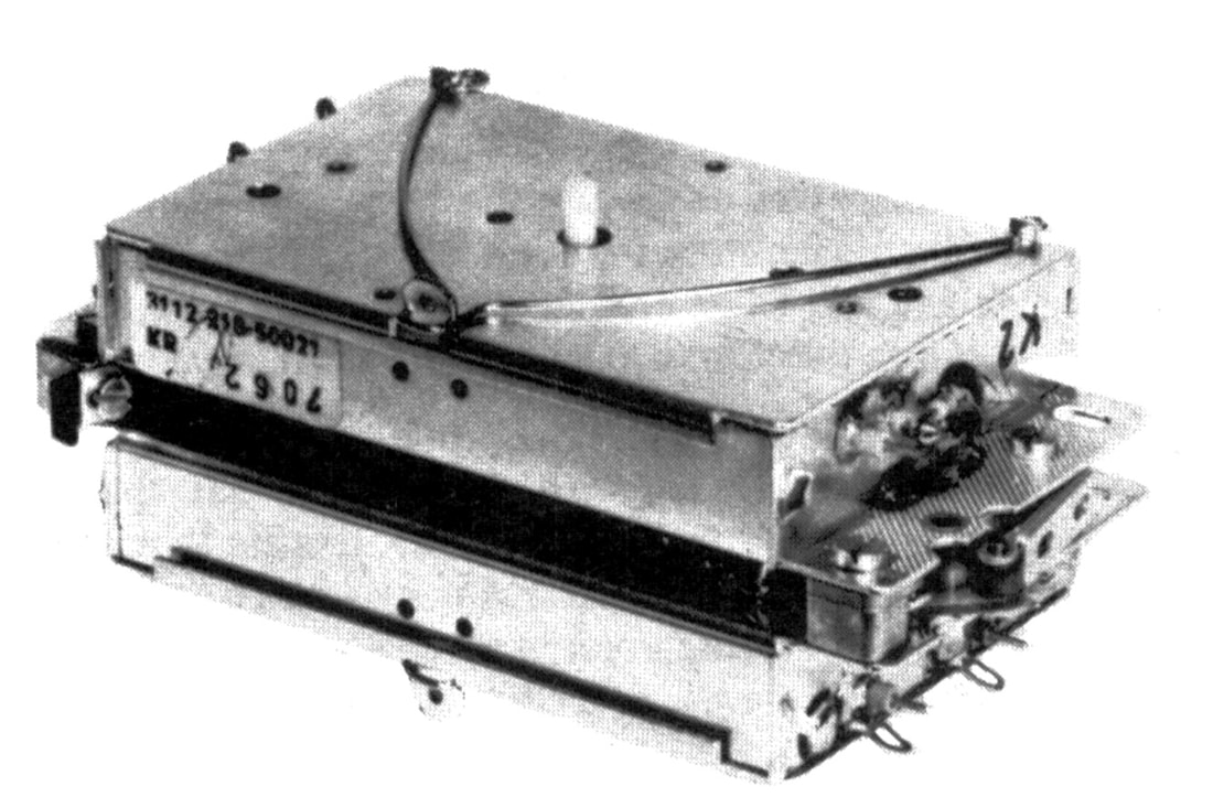
KD2 module built in Krefeld, 12nc 3112 218 50250. [Radiomuseum.org]
|
The KD2 in the K7 chassis D26K965, where the tuner panel is still a separate PCB. [Marcels TV Museum]
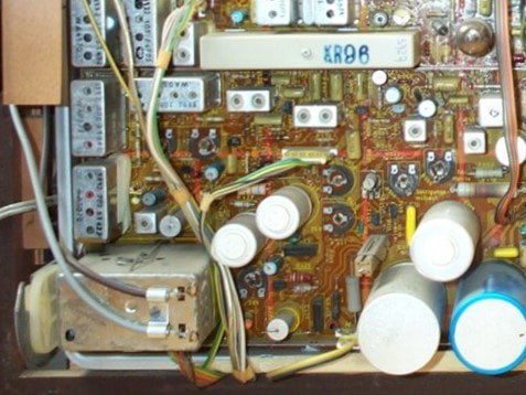
The KD2 tuner below left in the K8D television D26K160 "Goya 110 Luxus" from 1971. This was the first chassis where the tuner was standard mounted on the IF-video board. At the top of the picture the white PAL delay line marked KR96 is visible. [Ekhard Etzold's site]
|
Circuit diagram of the last Philips KD2 version, with additional varicaps in the input matching. [Philips KD2 Service Manual]
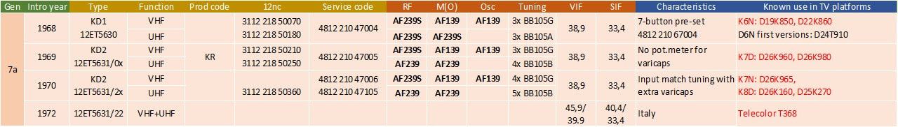
Overview of the KD1 and KD2 combo tuner family. Note that all tuners use PNP transistors exclusively (bold).
Silicon bipolar transistors
By the early 1960s developments in transistor design and manufacturing were accelerating, based mainly on the switch from germanium to silicon as the base material. This allowed for a number of innovations that would lead to increasingly better performing (RF) transistors. Without again going into all details, these were at a high level:
- silicon wafers; all silicon transistor and later integrated circuit (IC) processes were based on so-called wafers, tin slices of silicon cut from a rod of extremely pure silicon. Wafer sizes in this period quickly increased from 1 to 2, 3 and 4inch (25, 50, 75 and 100mm) diameter, allowing many transistors to be made on a single wafer;
- localized doping and implantation; by bombarding the silicon wafer with ions the material content can be modified, by either making it more negative (more electron donors, using e.g. Phosphor or Arsenic) or positive (more electron acceptors, using e.g. Boron, Aluminium or Gallium).
- mask-based lithography; using thin masks (similar to photographic films) areas where implants take place can be selected.
Using the planar silicon technology, the transistors initially offered similar or even lower performance as the germanium transistors; the silicon BF200 and germanium AF239 were roughly equivalent. Of course with the remark that the BF200 was an NPN while the germanium transistors were all PNP. This lower performance was mostly due to the fact that electron mobility in germanium is substantially higher than in silicon, resulting in shorter transit times and higher fT for a certain dimension. It therefore took a while for silicon to achieve RF performance compatible with germanium, when the lithographic dimensions of base-emitter structures were reduced to below 10 um. However, the Si transistors offered more reproducible results due to the better controllable implantation processes, so we see the binned transistors disappear. And although the germanium transistor "fought back" with the AF379 (even better than the 550MHz fT BF197/BF199), silicon definitely took over with the 2GHz fT BF480 introduced in 1974. Within the Philips group Mullard was apparently most aggressive in the use of silicon RF transistors. As can be seen in the family overviews of the U5 and UV1 tuners, Mullard introduced the BF180-family Si transistors in its UK tuners from 1968, two years earlier than the Eindhoven tuner development.
A last interesting development is that towards the mid 70s a series of PNP Si transistors was introduced with characteristics that were in principle identical to the the mainstream AF139 and AF367 Ge RF transistors. These were the BF939 and BF967, accompanied by the BF324 IF transistor. It was only after the introduction of these types that the Krefeld tuner development switched to Si transistors, allowing them to keep their PNP-based designs almost identical.
A last interesting development is that towards the mid 70s a series of PNP Si transistors was introduced with characteristics that were in principle identical to the the mainstream AF139 and AF367 Ge RF transistors. These were the BF939 and BF967, accompanied by the BF324 IF transistor. It was only after the introduction of these types that the Krefeld tuner development switched to Si transistors, allowing them to keep their PNP-based designs almost identical.
|
|
|
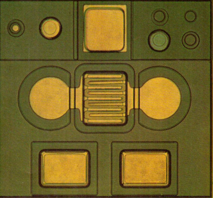
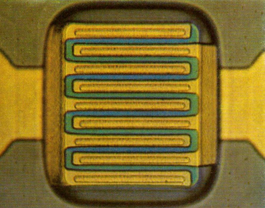
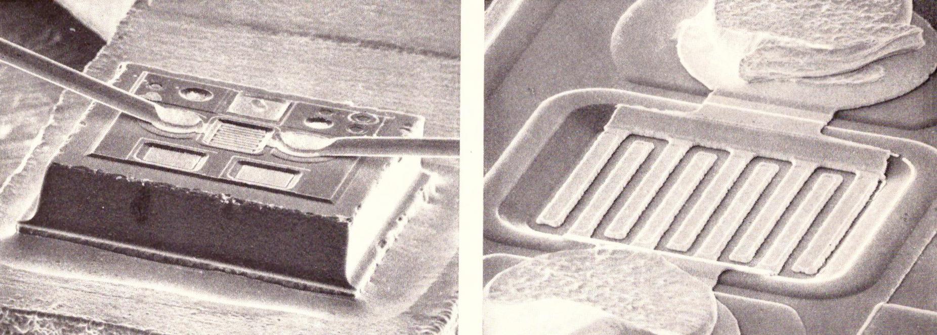
Four pictures of the Philips-Valvo BF979 silicon transistor, which was the one with the highest fT to date by the mid 1970s, and compatible with the germanium AF379. On the left a top view of the die, with the two circular emitter and base bond contacts. The square contacts are for optical alignment during production, the collector is contacted through the substrate. The 2nd picture shows further enlarged the base-emitter finger structure, with typical finger width around 2 um. Picture 3 and 4 show the transistor die after sawing, placement and wedge bonding inside the package. [Philips Valvo Brief "Si-PNP-HF Transistoren für VHF/UHF-Fernsehkanalwähler", December 1978]
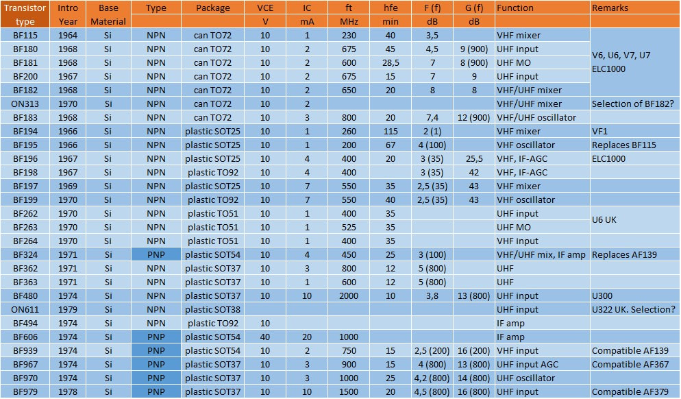
Overview of the silicon transistors used in Philips tuners between 1965 and 1985. ON types are non publicly released products, only used internally Philips. Often these were special selections (e.g. on hfe).
The V6-U6-V7-U7 mystery tuners, 1968
|
While the German tuner organization developed the KD1 and KD2 family of combined VHF-UHF modules, the Dutch development organization in Eindhoven went back - after the one-off AT7672 UV1 - to separate VHF and UHF modules. And these are for several reasons a real mystery! Until around 1964/65 tuners were always presented as integral parts of the television sets, and for each tuner a detailed service manual was available. As long as tuners were the old drum VHF tuners and "bath tub" UHF tuners they were assumed to be repairable, requiring the detailed service documentation. But by that time TV circuit diagrams were becoming increasingly complex due to the growing number of control loops and features, which resulted in the tuner being represented by a simple block drawing. Initially still indicating the valves or transistors used inside the tuner, but later not even that, and just a symbolical representation. At the same time the separate tuner service documentation disappeared. This was replaced, from 1968, by data books of the new Division Elcoma (Electronic Components and Materials), which contained a more classical sales specification of each module. Interestingly, or better frustratingly, one generation of tuners fell between the old and the new approach, the generation tuners that was introduced with the 2nd generation colour TV K7 in 1969. With only one exception, no circuit diagrams are known, only pinning and for the first few models the transistors used. For later models even this data is missing. And apart from 12nc's and service codes not even the names are given for the first versions. Because the 2nd implementation, introduced in 1971, was called V7 (VHF) and U7 (UHF), while the last non-varicap tuners were called V5 and U5, I have simply assumed that the first versions were called V6 and U6. Which I was later told to be correct, while I also discovered that this family had an official name: AT7690, which fits perfectly after the AT7680 UV1 family.
|
A typical appearance of the mystery V6 and U6 tuners: different size modules, mounted on a separate sub-PCB, placed anywhere inside the TV cabinet. This is an Erres RS9595, of the Philips sub-brand. [Marcel's TV Museum]
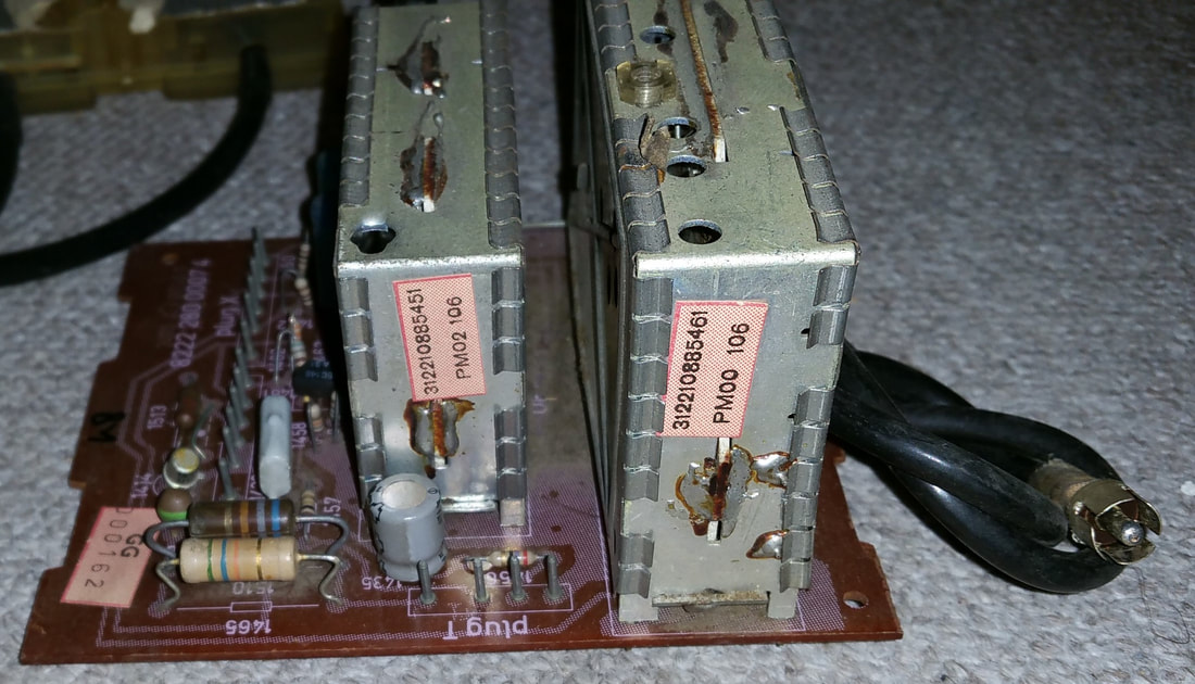
Up to the K8 chassis the tuners were mounted on a separate board. Here two Italian tuners produced in Monza (factory code PM) in 1971 week 6 (106). [Maurice Hamm]
|
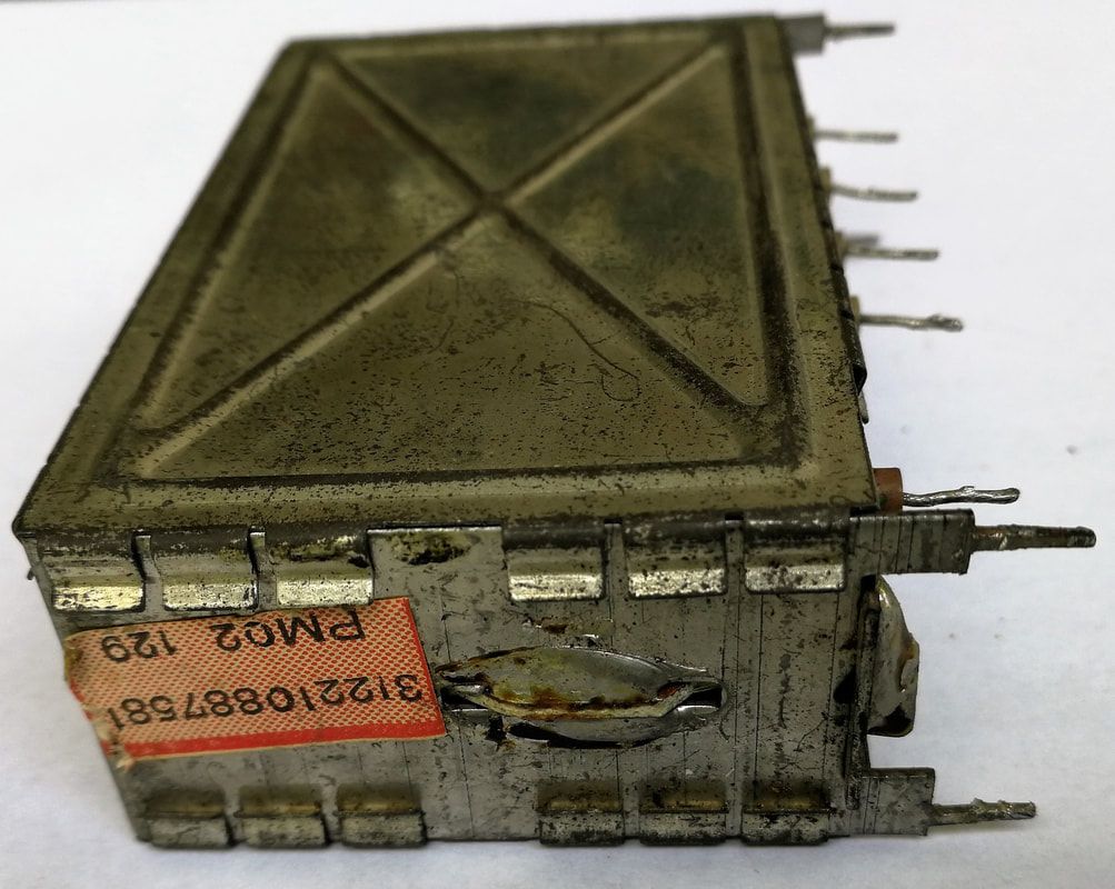
The Philips U6, 12nc 3122 108 87581. Produced in Monza, Italy, with code PM02, date code 129 so 1971 week 29. [Oswald Moonen collection]
|
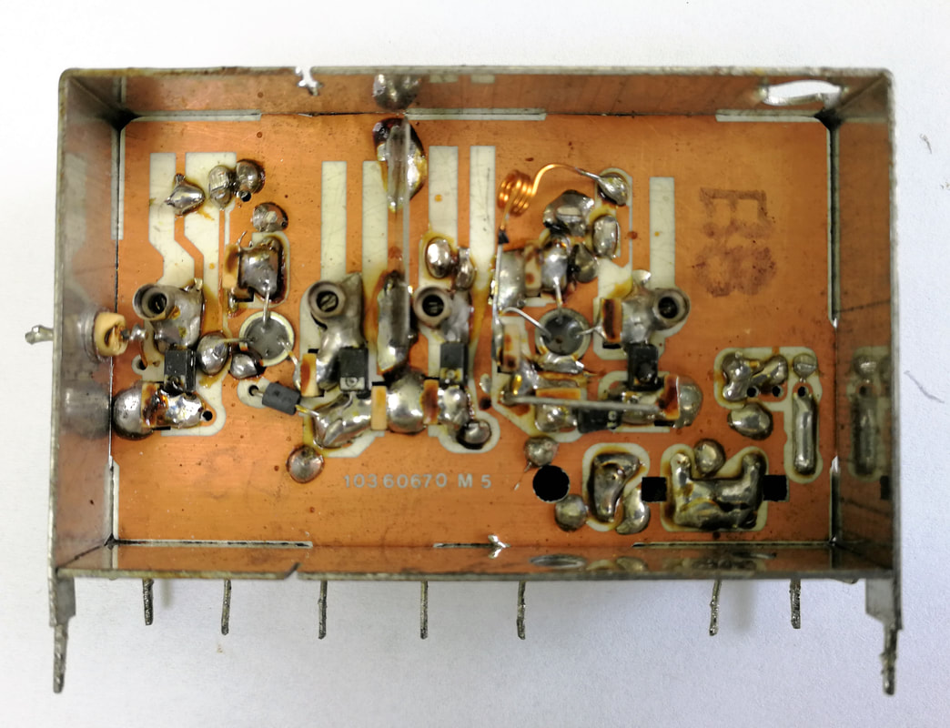
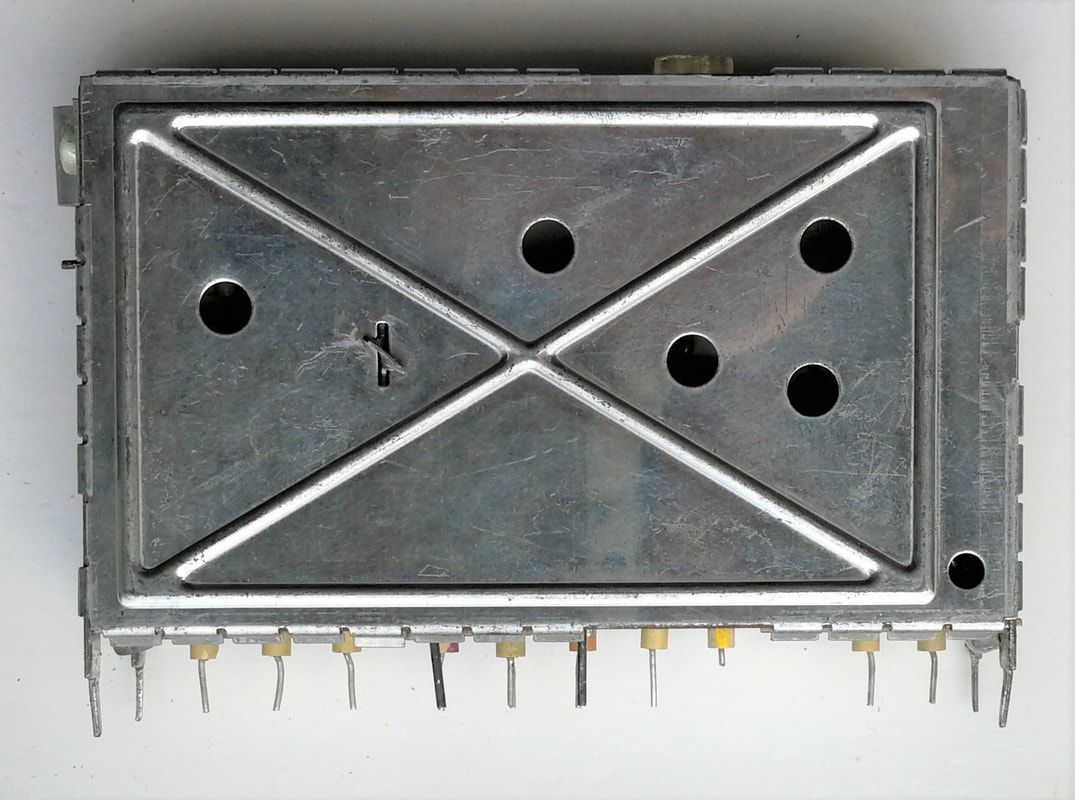
Bottom view of U6 tuner with the contact side of most wired components. The board is 2-sided ceramic, where this bottom side is mainly used for the ground plane apart from the soldering islands. [idem]
|
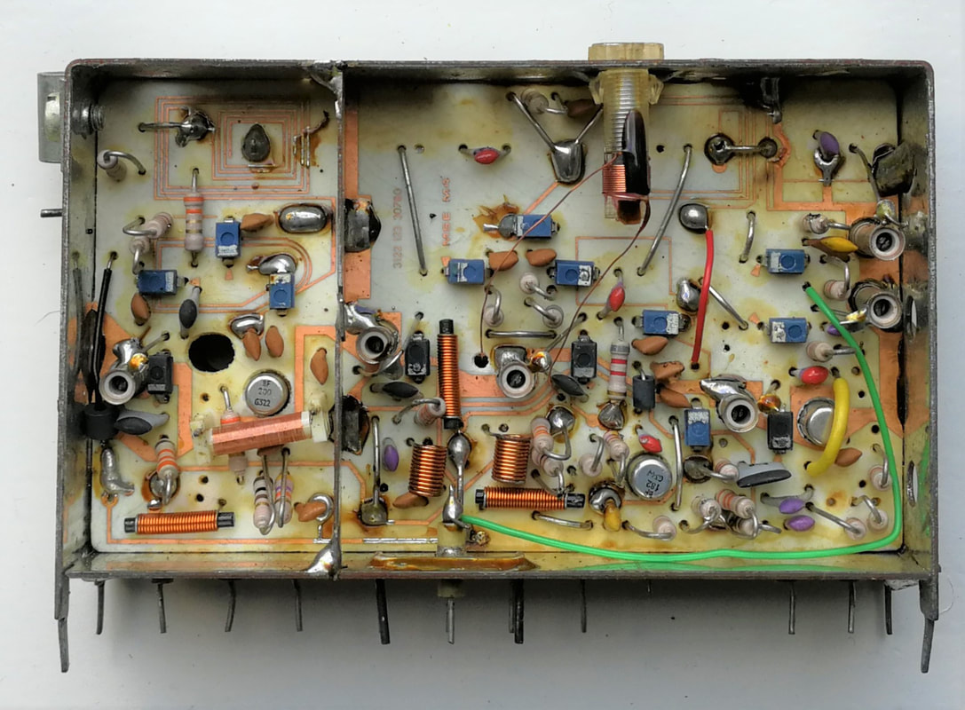
Top side interior view of the Philips U6 tuner. The two TO92 transistor cans are just visible. For alignment extremely thin ceramic trimmers were used and for decoupling ceramic plate capacitors sticking through the board.
|
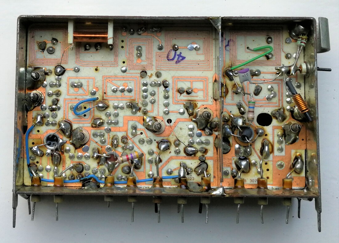
Bottom interior view of the Philips V6 VHF tuner. The printed coils form transformers with secondary coils on the other side of the ceramic board. At the RF input two wired ESD diodes are directly soldered to ground.
|
On the inside of the top cover was a plastic foil to avoid any of the wires touching the metal cover. On all pictures the ceramic feed-through pins are visible, which were not very sturdy!
|
Top interior view of the V6 tuner. The components are all the smallest form factor of wired components, and hand mounting and soldering must have been a nightmare.
|
The Philips V6M, 12nc 3122 127 11401. Note the extra standard-switching pin N in between two grounding pins. [Jac Janssen collection]
|
The main component side of the V6M. PCB lay-out changes are visible compared to the standard V6 above.
|
The primary copper-side of the V6M. Note that the large IF output filter inductor has moved to the upper left side.
|
Fortunately I obtained samples of the U6 and V6, see the pictures above, which reveal a lot about their design.
- these were the first real "tin can tuners", although the metal frame was still very basic. Essentially a U-shaped form soldered on top of the base plate with the capacitive feed-through pins. The V6 had one additional screen soldered inside the frame. The pins were essentially wires sticking out of the tuner, very thin and not rigid at all. Not easy for mounting on a PCB! Two identical covers were placed on both sides, with spring contacts for good electrical connection. No soldering.
- The circuit board is printed circuit board, with patterns on both sides. It had, for the period, very tight specifications, roughly four times tighter than standard CE PCBs: 250um line width and 25um tolerances, including that for the front-to-back alignment. The board had protrusions on the three non-bottom sides, which stuck through the frame and were externally soldered to it on both sides for solid grounding. One of the easier visual characteristics to identify these tuners.
- Inductors were partly wire wound (with or without ferrite cores), but the critical BPF and tank circuit coils were printed on the PCB substrate. Coupled coils were made by putting them on opposite sides of the board, which required the tight PCB alignment spec! Tuner alignment was done with ceramic tube capacitors, with very tiny interior screws for extending the core. Ceramic plate capacitors were used for low-inductance grounding, sticking through the main board.
- All components were discrete, although small form factor, and placing and soldering them must have been a nightmare. Assembling these tuners must have cost at least as much effort as the old mechanical ones!
- The VHF V6 tuner used a classical three-stage approach: a BF200 pre-amplifier, a BF182 oscillator and a BF115 mixer. Note that all three are new planar silicon NPN transistors! The V6 is switched between VHF-I and -III with pin C, which shortens parts of the VHF inductors using switching diodes in the same way as done in the KD1 and 2. A total of 8 switching diodes was used!
- The UHF U6 tuner used a BF180 RF amplifier and BF181 self oscillating mixer, undoubtedly very similar to the previous U5 generation, but with slightly improved performance due to the move from germanium to silicon transistors.
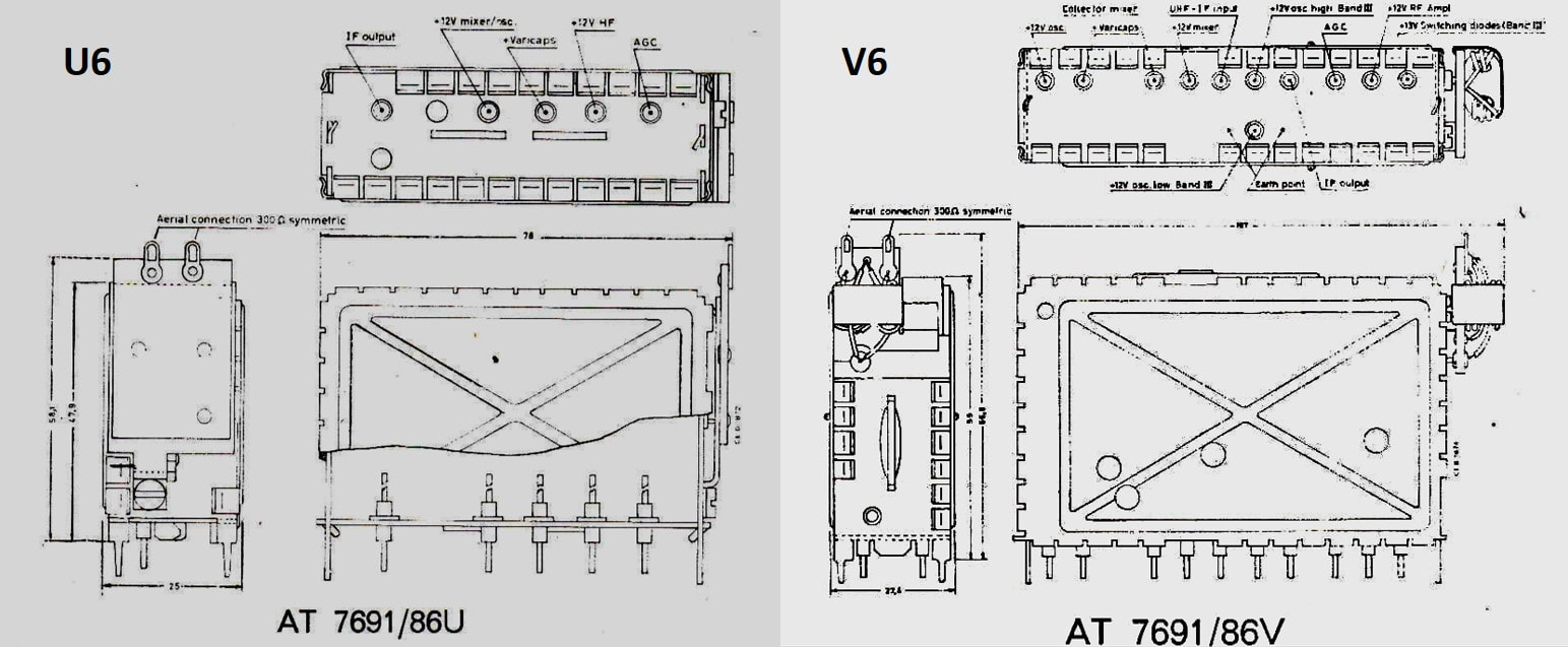
From the 1967 sales folder of the Belgian Philips affiliate MBLE: the - so far - single official drawing of the U6 and V6 tuners, which apparently also still had an AT family name: AT7691. These are the Belgian versions (suffix 86) including small external add-on PCB's with the 300-to-75Ohm baluns. [MBLE sales folder through Ite Weide]
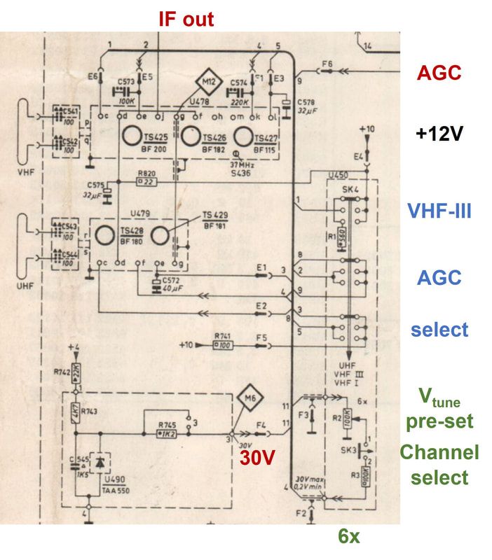
Circuit diagram of the Philips X24T712 black and white TV using the F6 chassis, showing the symbolical representation of the V6 and U6 tuners. The channel pre-sets, indicated in blue, were implemented six-fold, one for each channel. [Philips X24T712 Service Manual]
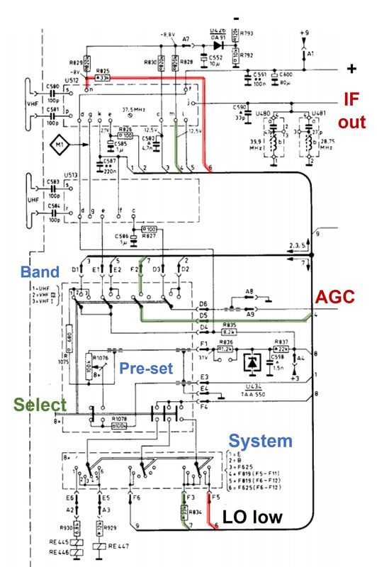
The V6M and U6 tuners in the Philips X24T712 B&W TV set from 1970. This was a multi-norm set covering all French standards and requiring VHF-III LO high/low switching. [Philips X24T712 Service Manual]
|
The picture on the left shows a typical application circuit diagram showing the V6 and U6, from which we can derive the following information:
There was one additional version of the V6 tuner, for the Belgian, Swiss and French multi-norm receivers. In these sets the individual channel pre-settings now comprised of three elements: the frequency band (VHF -I, -III and UHF), the system (standard B/G, the Belgian sound versions, and the French 625 and 819-line standards) and finally the individual channel tuning voltage. The complication here was the French VHF-III band, with the alternating "oscillator high" (for the even-numbered channels) and "oscillator low" (for the odd-numbered channels). For details see here. The channel selection arrangement is thus a bit more complex, as shown left. For VHF-I and UHF the operation is essentially identical to the standard arrangement discussed above, but for VHF-III additional switching took place. In VHF-III that band was selected through pin C on the VHF tuner, and additionally either pin M (odd channels with oscillator low) or pin N (even channels with oscillator high). The signal paths are indicated in green and red, respectively. Note that this chassis had 6 different standard settings:
From the information I have on the "V6-Italy" tuner it seems from the component count that the oscillator tank was switchable (D415 switching C448 parallel to C449), allowing the choice between the Italian 45,5MHz and standard 38,9MHz IF. |
|
One glimpse of the interior of the U6 can be gleaned from the information provided by the service documentation of the British CTV platforms Philips G8 and Pye769 (since 1966 Philips owned 60% of the Pye Company, and Pye sets rapidly became based on Philips components and designs). These sets only used UHF tuners, as shown right. Since the pinning and form factor are identical to the U6 I assume it is the same design, modified to 75Ohm input and using the latest bipolar RF transistors BF262 and BF263. Other than that the design is a classical UHF tuner, using Lecher-line filters.
|
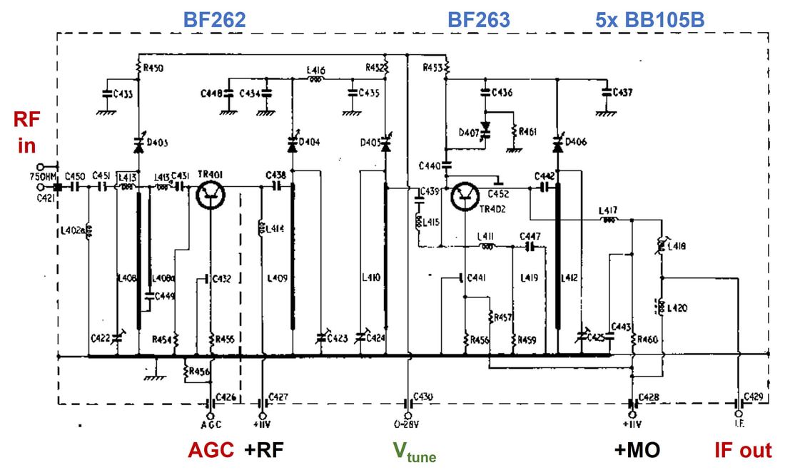
The Philips U6 tuner in the Pye 769 platform. [Trader Service Sheet 3041/T389 through Peter Blackett]
|
|
Although the flagship Philips colour TV set generations K7 (in 1968) and even the K8 (in 1970) were surprisingly both introduced with the UV1 mechanical push button tuner, both platforms switched to the V6 and U6 quickly, while the K8 then introduced the modified V7 and U7 tuners. As with the previous V6M and U6M, also V7M and U7M versions - for all clarity, this is my naming due to the lack of official type numbers - for the Belgian/French/Swiss multi-norm sets were introduced, used in the KM1 and KM2 platforms. Although the V7-U7 had a lot in common with the V6-U6, they introduced some modifications:
The V7 and U7 were widely used in all K8 derivatives for the different areas: the K80 was made in Sweden and Austria but also exported to the UK and occasionally even in the Netherlands. The KM1 and KM2 mentioned earlier were other examples. In all these sets the tuners were placed on a small PCB that could be positioned anywhere in the increasingly crowded CTV cabinets. The K80 Service Manuals are the only ones officially using the V7 and U7 names for the tuners!
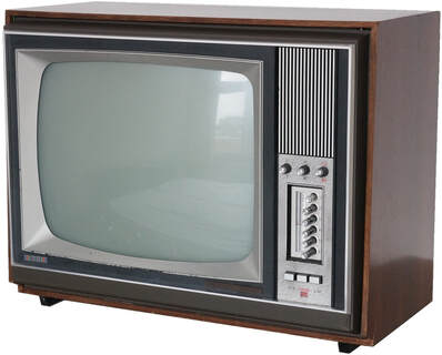
A typical K7 or KM1 chassis from 1969-1970. This an Aristona sub-brand version, the AR48K041. [Technisch Museum.nl]
|
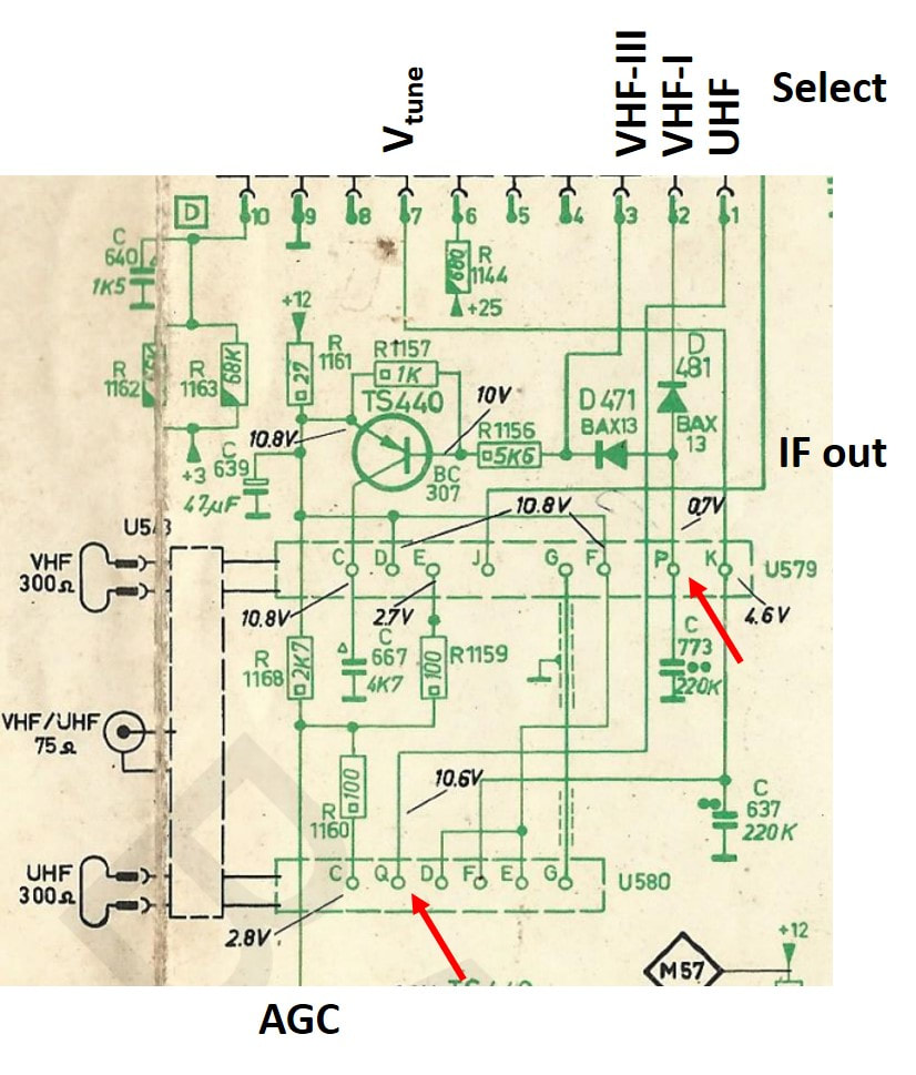
Circuit diagram of the K8 chassis, showing the application of the V7 and U7 tuners. The new Selection pins P and Q are indicated. In VHF-III both pin P (through D471) and pin C (through TS440) are selected. [Philips K8 Service Manual]
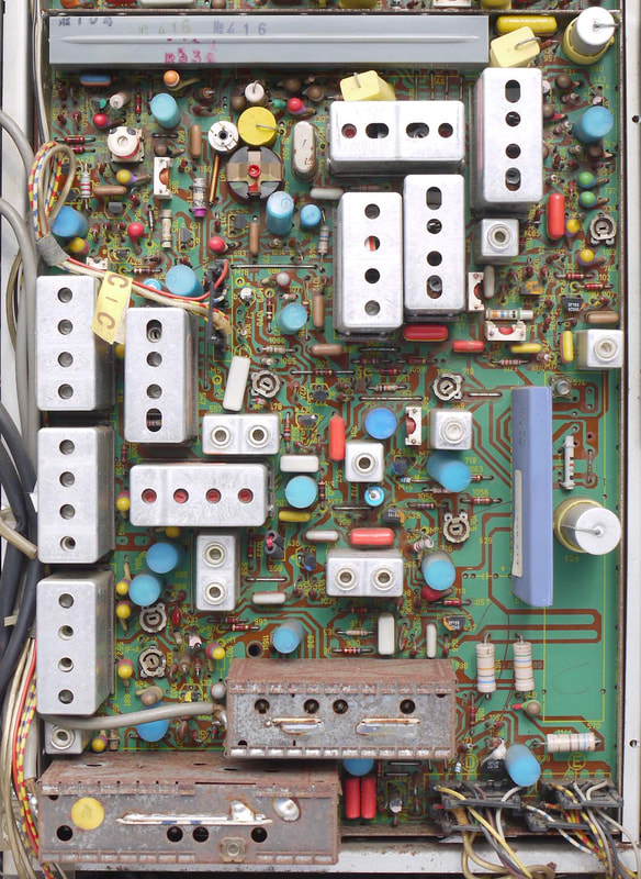
Witht he introduction of the V7 and U7 tuners in the later K8 colour and F6N black-and-white chassis, the modules moved onto the small-signal panel! Here the two modules, rusted after many years in the field, in a Norköping K80 chassis, the S26K624. [Marcel's TV Museum]
|
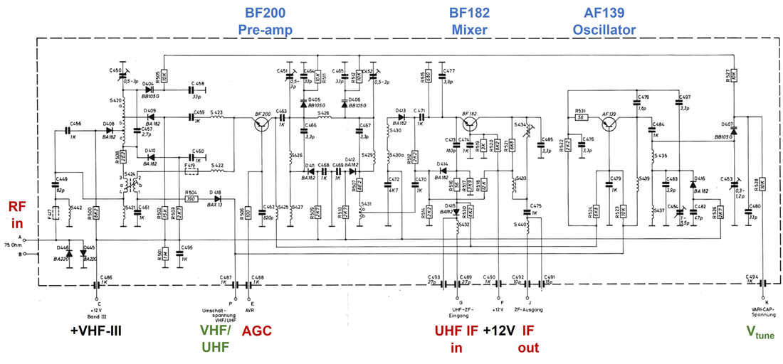
Finally a circuit diagram of the V6-V7 family of VHF tuners! This is the V7, showing the separate pin P for VHF/UHF switching, separated from the MO basic supply. [Philips S26K515 Service Manual via Radiomuseum.org]
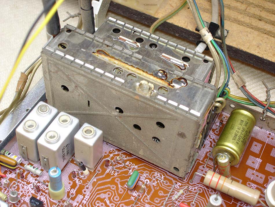
From the outside the V7 and U7, here seen in the X24T753 late version of the F6 B&W platform, looked identical to the V6 and U6. From this time onwards the tuners were also no longer on separate sub-PCB's, but located on the larger IF-panel. [Marcels TV Museum]
|
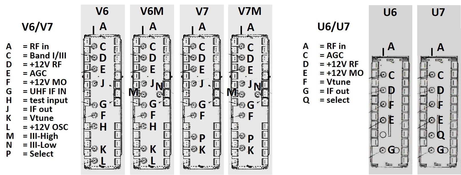
Because of the lack of documentation on the V6/U6 and V7/U7 models, using their pinning and connections was one of the few sources. Which in turn was a nightmare because of the strange naming of the pins and their changing order in the footprint. Above therefore the result of my struggles.
|
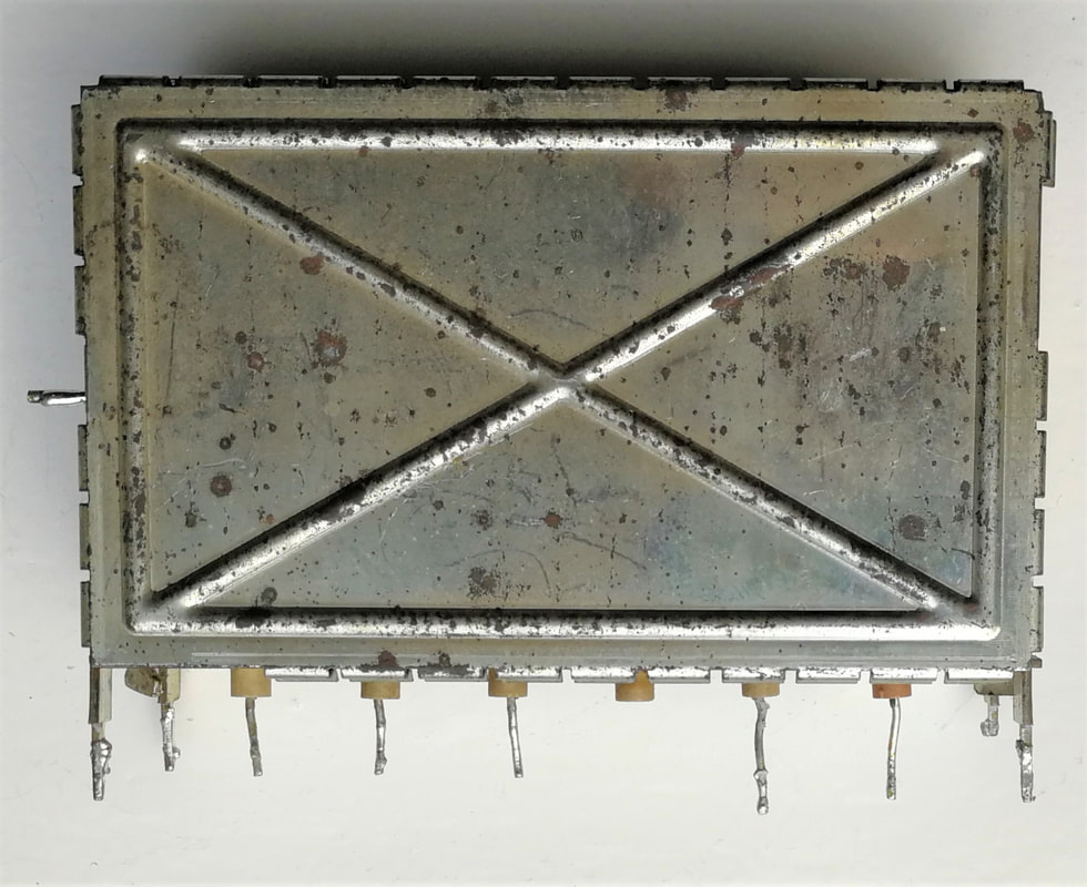
The Philips U7 tuner, recognizable from its 6 pins (the 4th is broken on the picture). [Jac Janssen collection]
|
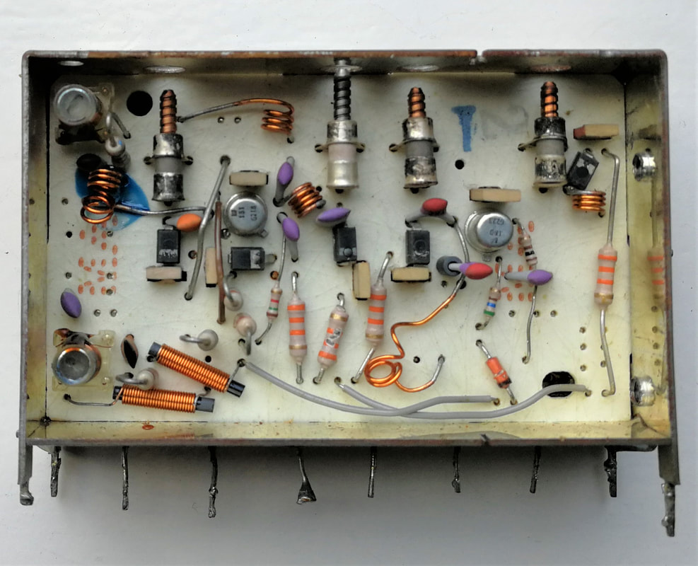
Component side of the U7. Note the single-sided board. Although electrically still very much identical to the U6, the interior was completely re-designed.
|
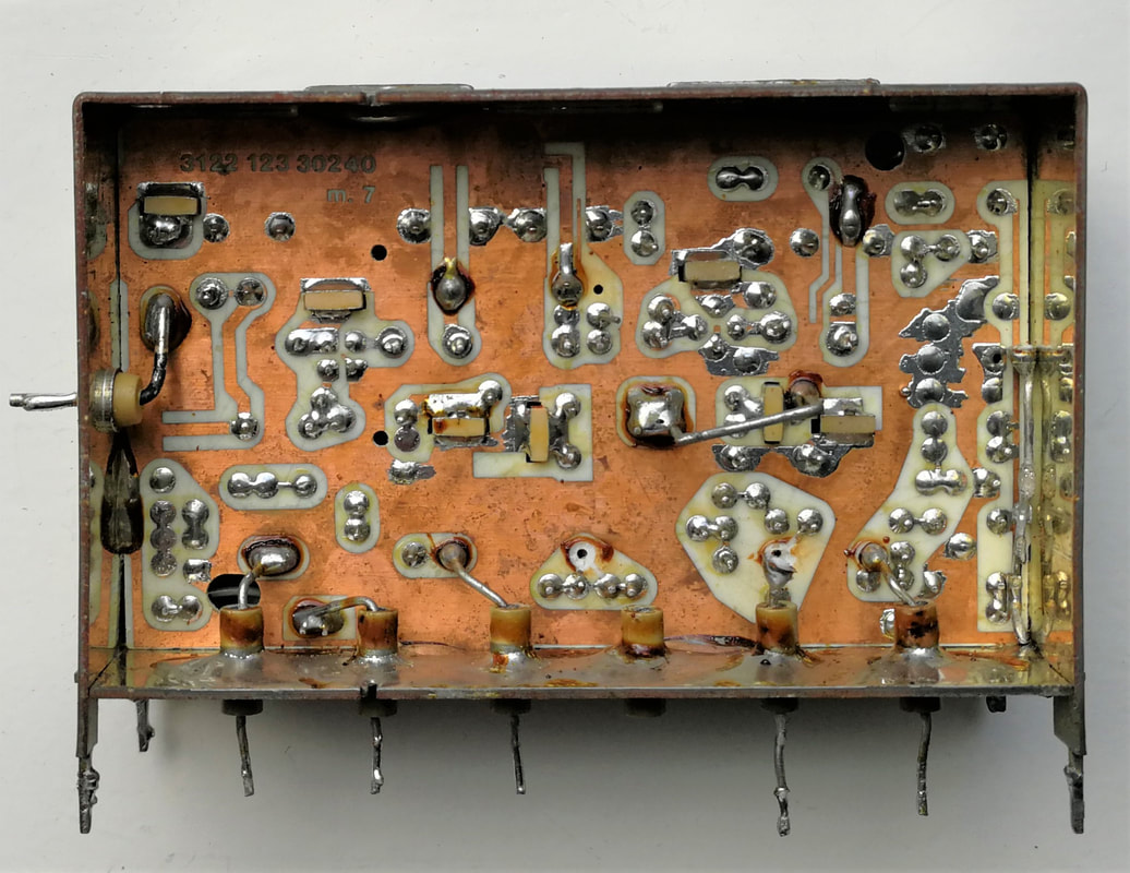
The copper-side of the U7 circuit board.
|
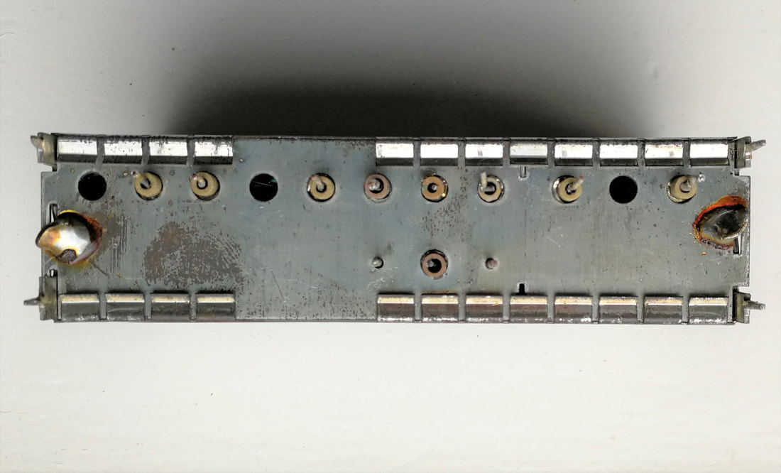
The Philips V7 VHF tuner 3122 127 10351. Despite the 12nc and pinning referring to a standard CCIR-B/G tuner, it carries
the standard-switching pin N on the lower row. This tuner was used in the X26K176 K8 chassis. [Jac Janssen collection]
|
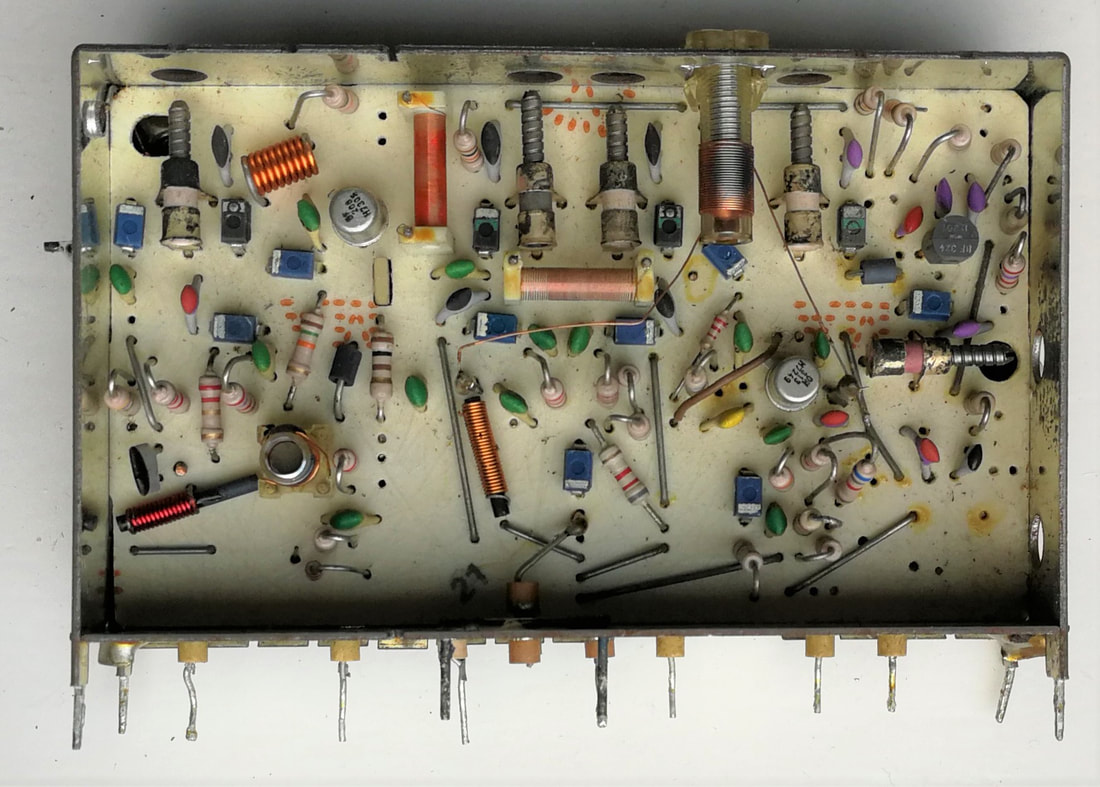
The V7 component side of the now also single-sided PCB. On the far right the PNP transistor BF324.
|
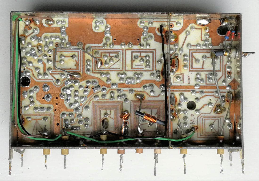
The V7 copper-side. Because of the lack of two levels, routing has become problematic and for DC some wires are required.
|
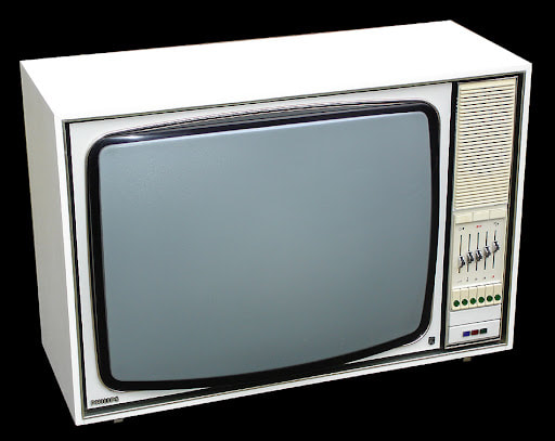
The Philips K8L chassis still used the U7 and U7 tuners on a separate sub-board. Here the X26K176. For the channel selection it used soft switching buttons (six on row) but it introduced the extendable drawer with the channel pre-set (below the buttons). [Marcels TV Museum]
|
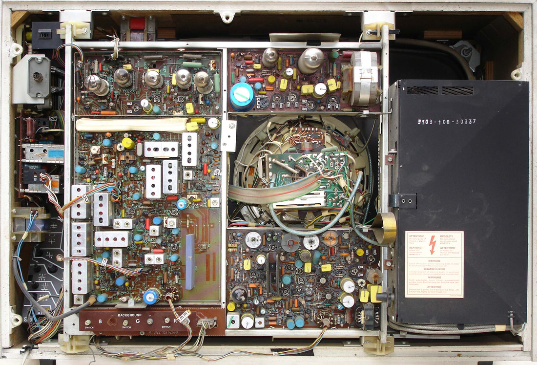
Rear view of the K8L X26K176. The two tuners on their sub board are visible in the gap near the main PCB on the far left. This chassis still used 7 valves, mainly in the deflection circuitry on the upper side of the main board. [Marcel's TV Museum]
|
The last K7 and new K8 CTV chassis was very succesful, produced in many countries including the derivatives K80, G8 and KM1. In parallel the F6 and its derivatives F6B and F6N remained in volume the main chassis for black and white. It is no surprise that also the associated V7 and U7 tuners were produced on multipe locations. In one aspect they seem to have been a milestone in the tuner history: the last generation volume produced in Eindhoven on the Strijp-complex in building SK (production code A). From here on the Eindhoven tuner fab would only produce specialties, new products (like the splitter and modulator modules for the new VCR product) or as pilot line. The Eindhoven volume production in fact moved to Volt in Tilburg (production code V). Other major production sites for V6/U6/V7/U7 were Monza (PM) and Kopenhagen (K), while the U6 British version was produced in Dunfermline (BY). Krefeld and Wesel are missing in this overview because they were producing the locally used KD1 and KD2 tuners.
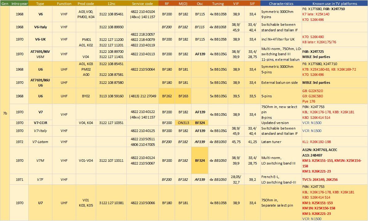
Overview of the Philips V6/U6 and V7/U7 tuner family. Only the type names in bold are confirmed, the others are my interpretation. As always the TV names in red are CTV, black are B&W, bold multi-norm. The V6-U6 and V7-U7 are almost identical apart from the additional VHF/UHF switching pins on the second ones. Note the U6 UK tuner, which was the only one introducing the next generation silicon bipolar transistors. At the same time the oscillator transistors switched back to germanium PNP's.
Channel pre-setting and selection mechanisms, 1966-1972
|
We should not forget that many of the developments of the tuner (introduction of transistors, varicaps, size reduction) were very much driven by the desire to simplify the channel selection process for the TV viewer, primarily to get rid of the manual operation of the tuner rotation knobs. In the valve days this led to such complex constructions as the motor-controlled tuners, but this was way too expensive and bulky and never made it beyond a few of the most high-end sets. It was the UV1 AT7672 transistorized tuner that allowed the first step forward: the 6-button individual preset mechanism, described here. This concept evolved into the ultimate push-button pre-set tuner assembly: the AT7672 for the 4-norm Belgian sets.
Next to the standard AT7672/UV1 tuner that provided per push button band-preset and channel preset, the multi-norm version required additionally standard-preset. This was done with two additional switches: SK3 was added at the bottom of the switch mechanics and operated by the push buttons, selecting the switch associated with the channel SK4 that were mounted at the back of the total assembly. SK4 could be set to CCIR-B/G, CCIR-C/F/H Belgium, CCIR-L France UHF or CCIR-E France VHF. Note that the standard selection didn't influence the tuner settings, only video bandwidth, VIF-SIF distance and sound AM/FM selection. All in all this was the biggest mechanical selection assembly after the HA 353 50 and as such the ultimate effort in this direction. But in the 1966-67 period this was the standard solution for all high end Philips TVs, both Black&White and Colour. So the Dutch K6, K7 and even the first K8 CTV chassis used the AT7672, as well as the Belgian KM1, French TVC4 and British G6 versions. The German D6 chassis was the only exception, using the Pi1 tuner, but in combination with a conceptually identical 6-button mechanical pre-set unit. Four more detailed pictures of the AT7672/84 4-norm tuner with both channel and norm pre-setting buttons. [Oswald Moonen collection]
With the introduction of the U6 and V6 varicap tuners an enormous simplification in the channel selection mechanics was possible, essentially because no mechanical transfer to a variable capacitor tuning axis was required. Switches were still needed to select the appropriate tuning voltage to be connected to the varicap inputs, but this no longer required any mechanical connection. For the first time the tuners could be located at any location within the TV cabinet! Initially the external look and feel was kept as it was, i.e. the 6 well-known pre-set and selection push buttons, but now in a substantially simplified form, shown below. Essentially the module reduced to 6 potentiometers and 6 switches, where the most complex mechanical construction was the one for the channel indicator needle. The electrical circuit is as shown in the U6-V6 section above. This module was used in upgrades of the K7 platform, in combination with the U6 and V6, in the K7D in combination with the KD1, and as standard solution in the K70 and K8 in 1969-70.
|
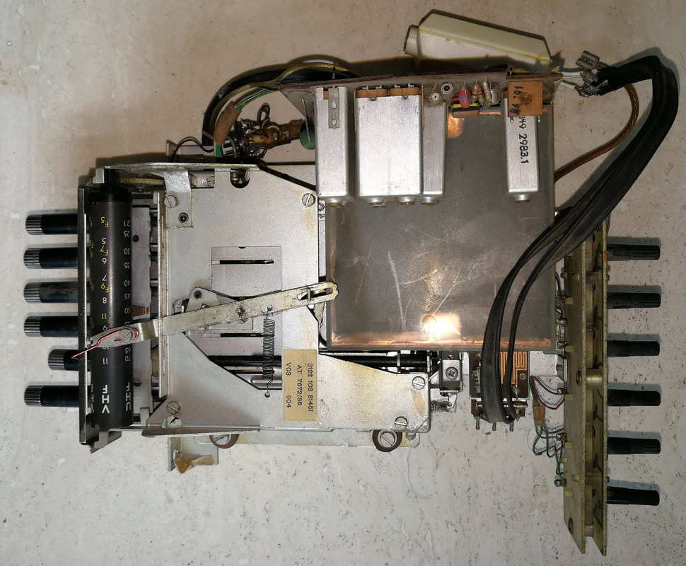
The AT7672/86 4-norm channel selection assembly. On the left the mechanical push-button pre-setting and selection mechanism; in the centre the plastic cover of the UV1 tuner; on the right the standard selection switches for each of the 6 channels; at the top the PCB with the first IF amplifier and BPF, directly soldered to the tuner IF output. [Oswald Moonen collection]
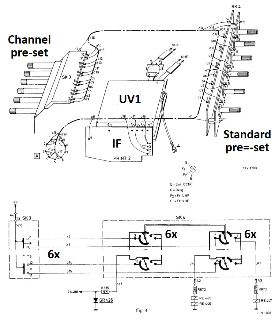
The circuit diagram of the multi-norm pre-set system in the X19T652, using the AT7672/86 assembly. [Philisp X19T652 Service Manual on Radiomuseum.org]
1970 advertisement showing two TV sets with the preset push button channel selectors. The largest set on the right is a K7 chassis. [Philips reclamekunst]
|

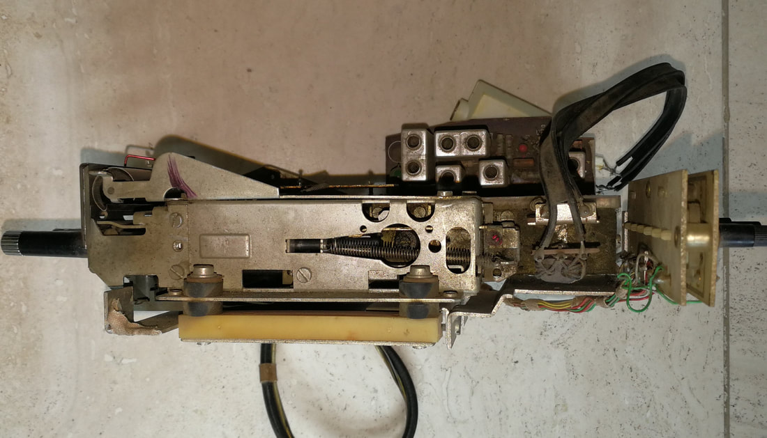
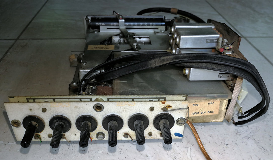

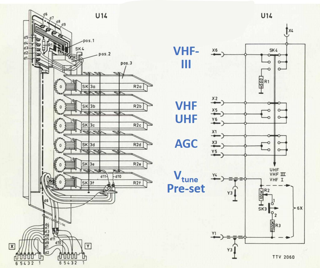
The simplified 6-button channel pre-set and selection module (12nc 3122 108 83381) introduced in the K8 CTV chassis in combination with the U6 and V6 tuners.
[Philips K8 Service Manual at Nostratech.nl]
|
The white gear wheel was mounted directly on the button axis. When rotated it would move the slider of the potentiometer and the upper brass gear wheel visible in the pictures. The latter wheel on its threaded axis would move the spring-operated metal bracket more or less backward, to which the red tuning indicator needle was fixed. [Oswald Moonen collection]
|
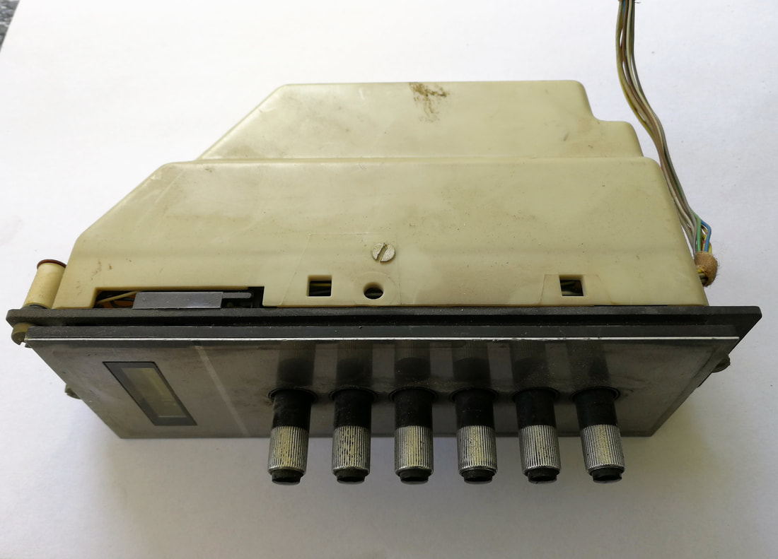
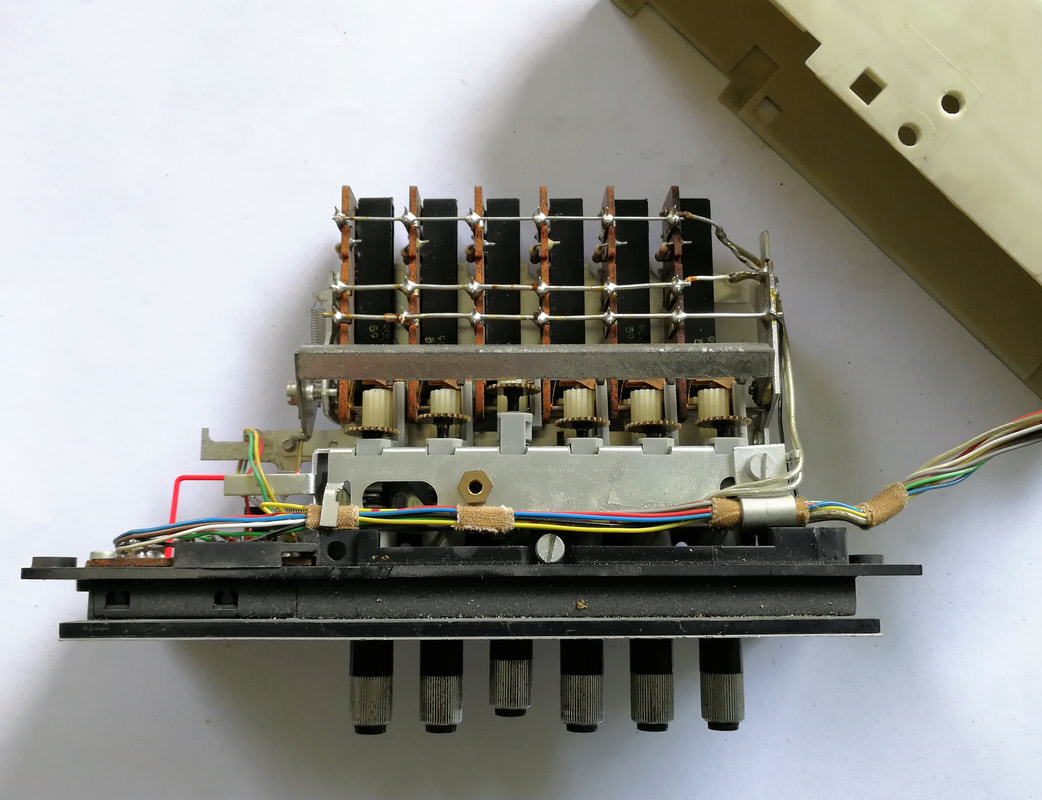
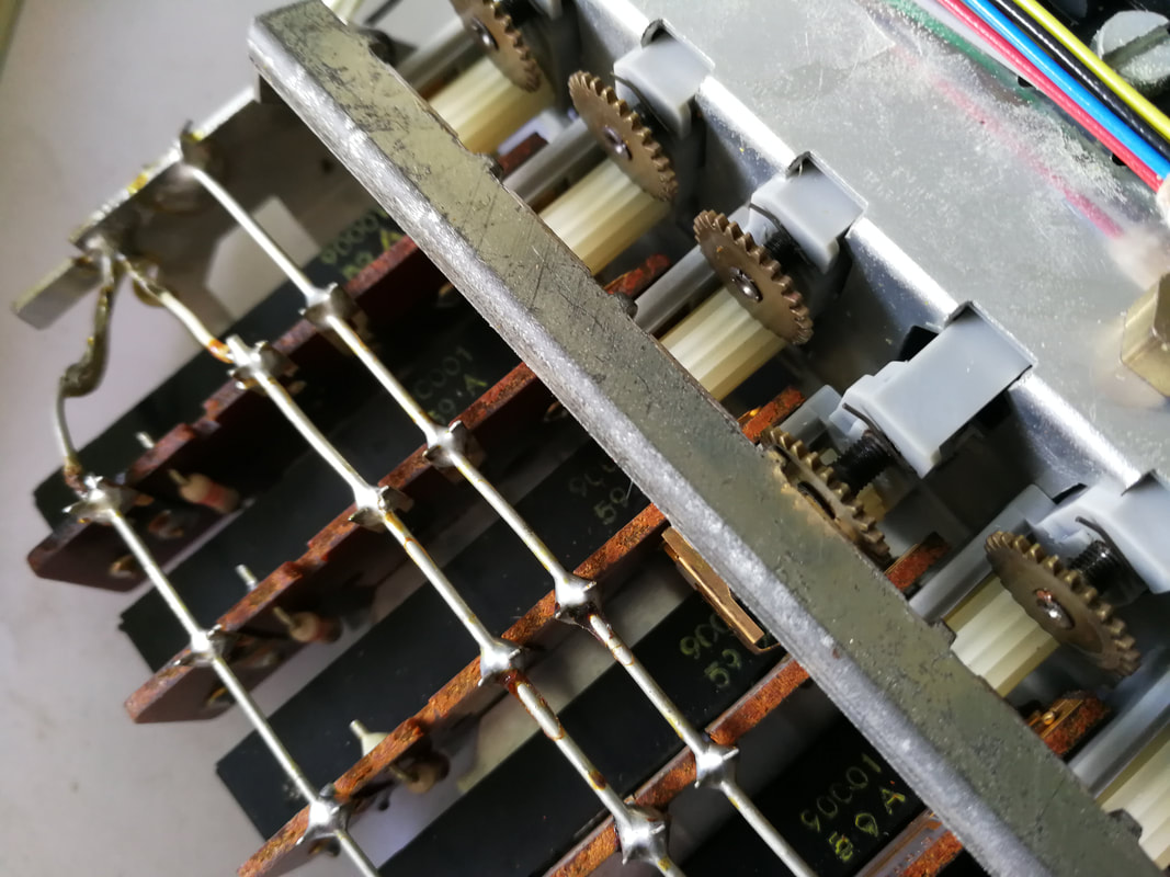
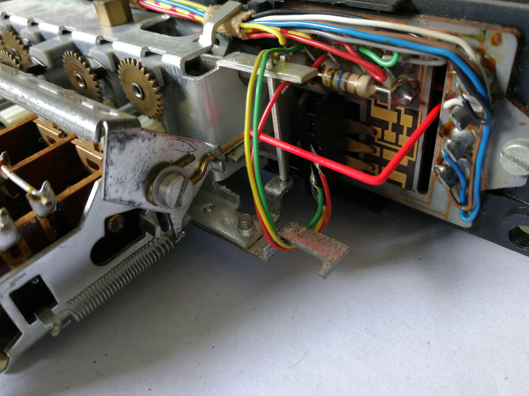
The third, and conceptually most important step, came with the introduction of the pre-set panel, which separated the pre-setting from the actual channel selection. Pre-setting was now done with a small and simple potentiometer (for the channel pre-set) operated through a small thumb-wheel, and a small switch (for the band pre-set). This panel was hidden inside the front panel and could be extended like a small drawer. The actual channel selection was now done by 6 simple push-buttons on the front, or alternatively using an ultra-sonic remote control. These pre-set panels were introduced in the K8L later models of the K8 and K8D in 1971, as well as the KM1L in 1972. However, the latter chassis still had the 6 standard pre-setting switches on the back panel of the TV. On later models the number of channels was increased to 12 by adding a second pre-set panel.
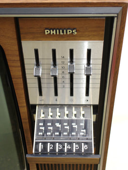
|
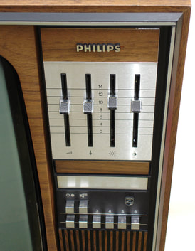
|
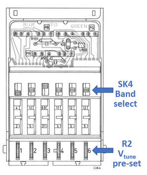
|
The new pre-setting panel on the left in extended position, in the centre in normal closed position. The bottom row are the 6 channel selection buttons, operating just regular switches. [Pictures of the Philips X24T753 on Marcel's TV Museum]
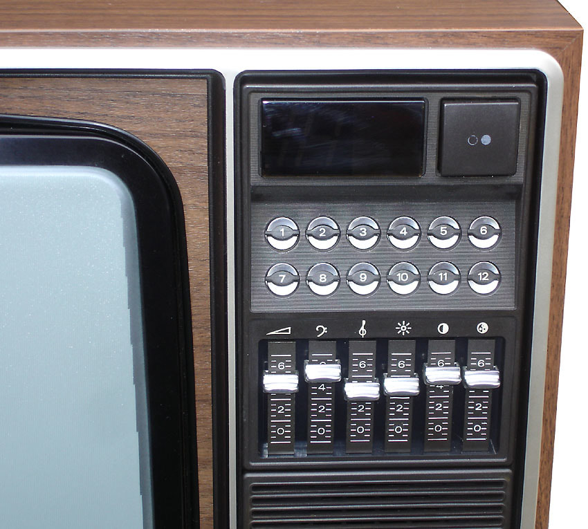
The 26C568 K11 CTV, with twelve tip touch channel pre-sets, LED segment channel number display and 2 pre-set drawers for 6 channels each (below). [Marcels TV Museum]
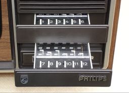
|
The last step towards ease of use before the remote control would take over was the famous Philips "tip touch" button. This was essentially a capacitive sensor, where the human skin, when touching the two contacts, provided a high-ohmic discharge path, thus lowering the voltage across the sensor. Because the sensor was only touched temporarily, a form of memory was required in order to keep the tuner at the selected channel. This was done using the SAS560 4-channel flip-flop (FF) integrated circuit in a 25V bipolar technology, one flip-flop per channel. When switched on, the FF operated activated output switches integrated in the same IC, providing 12V outputs. These outputs drove one reed relay each, acting as a low-ohmic switch for the channel pre-set tuning voltage, and transistor switched for a neon indicator light and the band and mode switches. Again, not a very cheap solution, but, given the direct user benefit, apparently deemed worth the money. The tip touch sensor was introduced in 1972 as an option in the K9 chassis and then standard from the K11 in 1975. In the Super de Luxe K9 chassis the outputs also drove a Nixie-tube channel indicator, in the K11 this became a LED segment display. In general the tip touch was a major feature for all Philips consumer equipment, also used on the audio radio and amplifiers, tape recorders and record players.
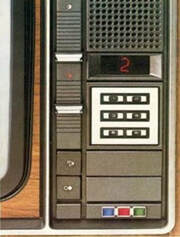
The very first tip touch six channel selector on the K9 X26K206, with a Nixie-tube channel display above it. [Philips 1973 product folder]
|
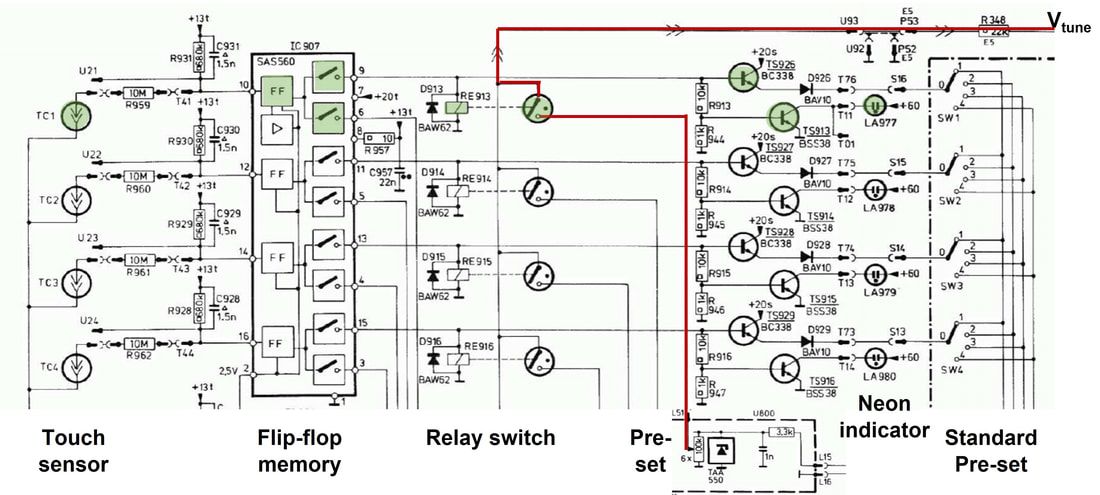
Circuit diagram of the tip touch channel selection in the K9, K11 and KM2 chassis. Only 4 channels are shown. The green blocks are switched on when the channel 1 button TC1 is touched. Red shows the path of the pre-set tuning voltage to the tuner varicaps. [Philips KM2 Service Manual]
In parallel to the touch control, the K11 chassis also saw the introduction of the wireless, ultra-sonic remote control. As mentioned earlier, the ultra-sonic fron-end, although strictly spoken no RF, was developed in the Edens Tuner -lab. For the history of the Philips TV remote controls follow below link.
The Elcoma tuners, 1970-1973
This section has been substantially shortened compared to the original text.
In 1970 a quite exceptional phase started, which has cost me some time to understand. Recent explanations by people directly involved have finally made it clear. As mentioned earlier, the basic agreement between the HIG RGT (responsible for TV and dedicated TV modules like tuners) and HIG Elcoma (responsible for standard components) was that the latter would sell the RGT tuners (and other TV-specific assemblies) to the third market. And at the same time Elcoma would and could sell the components primarily developed for Philips. Where one of the main selling arguments was that if the leading TV player Philips used the components they must obviously be state-of-the-art (which they mostly were!). However, there were some structural issues: firstly the TV organisation only wanted to allow sale of its tuners with a 1-2 year lead time, meaning that Elcoma was never offering the latest tuners. And secondly the RGT tuner organization didn't have the bandwidth for developing customer-specific derivatives requested by Elcoma. But the most important breaking point was the varicap. Mr Edens, the head of the RGT Tuner-lab, stated that with the first varicaps developed by Elcoma he could not make decent tuners. Which was factually true - the varicaps had still too much series resistance as mentioned earlier - but politically undesired, at least by the Elcoma management who wanted to sell their varicaps to the external market. But external customers were usually hesitant to buy components that were not yet used by Philips internally.
By the end of the 1960s this came to the point that Elcoma lost its patience, and it was decided tuner development in this HIG, focussed on external customers. This would allow them to use the latest components developed in the Elcoma semiconductor groups, especially the varicaps, while the tuners could be tuned to the specific customer specifications.
|
In 1970 the Elcoma tuner group was established at the new Beatrix complex on the western limits of Eindhoven. The group was housed on the 4th floor of the main building BE, so BE4, with mechanical development done by the factory automation group on BC-1.
As leader of this activity Philips hired Heinrich Bender, who had been leader of the tuner development at the German company Standard Elektrik Lorenz (SEL) and author of a book on tuner development. His group was initially around 5 engineers, and started working on the ELC1000, based, as we will see, on an entirely new approach of modular printed circuit boards. Tuners developed by Elcoma naturally obtained different 12nc codes than the RGT tuners: 2422 542 1xxxx instead of 3122 127 1xxxx (for Eindhoven) or 3112 218 1xxxx (for Krefeld). One as yet unexplained issue is that also the VD1/UD1 Krefeld tuners changed their 12nc during this period, to 9012 745 xxxxxx. I have the impression the 90-code was a kind of reserve code or "not yet allocated to a HIG"-code, because the Krefeld TV-centric organization did not want to use Elcoma codes. Only speculation! Elcoma tuner manufacturing was done in one of its wired assemblies (deflection coils) factories in Grâce Hollogne, near Liège, Belgium. This activity was stopped in 1972, with ELC1000 production moving exclusively to Valkenswaard, 10km south of Eindhoven, a factory that had so far produced magnetic ring core memories and valve sockets. |
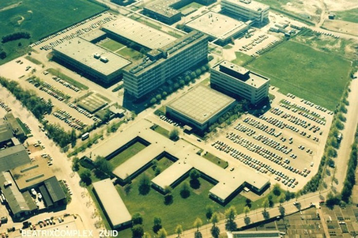
The Philips Elcoma Beatrix-complex which opened in 1967. The Bender-group developing the ELC1000 tuner was located on the 4th floor of the big high-rise building in the centre (BE4).
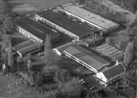
The Philips Elcoma factory in Valkenswaard. From 1970-1975 it produced also ELC1000 tuners. [Heemkundekring Valkenswaard]
|
Elcoma ELC1000 modular tuners, 1970
Looking back at the first twenty years of Philips tuner development up to the new tin can tuners, it must be said that in general developments had been steady and consistent, next generations building on the experience obtained with the previous ones and innovations mainly in the introduction of new components. The only exception to these were the Pi1 and UV1, which radically broke with previous mechanical and electrical concepts, in an effort to design combo VHF-UHF tuners. Both were replaced in the Philips TVs, however, by the new tin can tuners V6/U6, V7/U7 and VD1/UD1, where VHF and UHF were again separate modules. Nevertheless the desire for different and more flexible concepts survived, especially within the rapidly growing Elcoma components division and its desire to grow external business for customers with different requirements than the internal RGT tuners that were offered. The result was a new and different tuner family, the ELC1000, that again combined VHF and UHF in a single can:
- The form factor was new, consisting of multiple, different PCBs (one per frequency band) that were again mounted on a mother board PCB. The tuner could be delivered either as mother board with mounted sub-PCB's for each band, or with the mother board mounted on a base plate and the ensemble covered with a tin can.
- Some bias resistors were mounted outside the can on the base plate, such that customers had a lot of freedom in setting the tuner performance.
- The module could be mounted either horizontally or vertically, facilitating design-in.
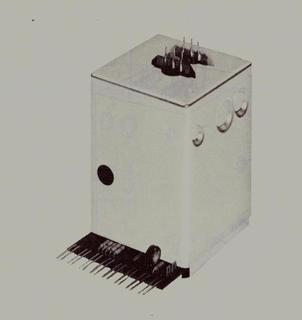
Picture of the Philips ELC1000 family of modular tuners. The RF connectors are on the top, at the bottom the base plate with biasing components. [Philips Elcoma Data Book CM3 February 1972]
|
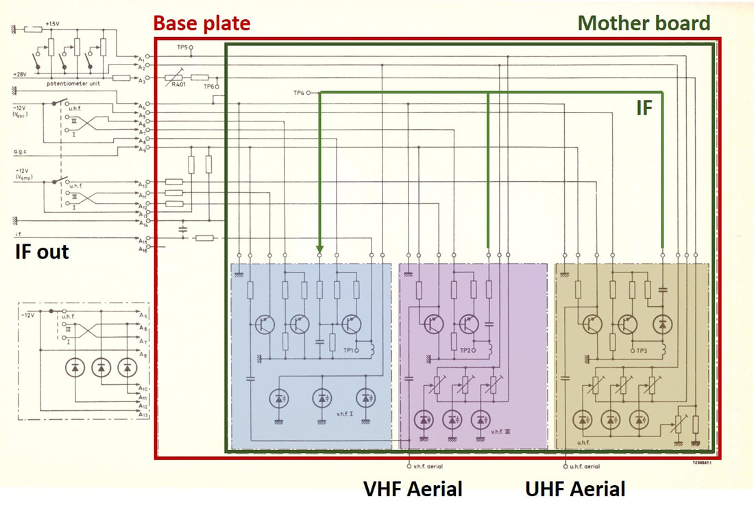
Conceptual circuit diagram of the ELC1000 tuners. Note: not the full circuit diagram; only the transistors and alignment varicaps are indicated. All filtering functions are omitted. The green line indicates the loop back of VHF III and UHF IF to the IF amplifier on the VHF I PCB. [Philips Elcoma Data Book CM3, February 1972]
|
For each of the band modules the design was straightforward: pre-amp, double tuned BPF, oscillator. The VHF I board had an additional BF115 IF amplifier, which was also used in the VHF III and UHF modes. A lot of attention was paid to design-in flexibility, so both the low end (around 3V) and upper end (28V) tuning voltages could be adjusted for each band. Power supply was also flexible and could be higher than 12V, in which case the customer needed to adjust the series emitter resistances on the base plate. The transistors used are the same as those in the V6-U6 contemporary tuners.
Apart from the form factor and the revolutionary modular design, one of the major differences between the ELC1000 and RGT tuners was the alignment procedure. In classical tuners this was mostly done by adjusting the tank circuit or BPF inductors. In the ELC1000 the alignment was also done by changing the DC bias of the varicaps using potmeters. Especially in band III and UHF every varicap had its individual bias correction.
Apart from the form factor and the revolutionary modular design, one of the major differences between the ELC1000 and RGT tuners was the alignment procedure. In classical tuners this was mostly done by adjusting the tank circuit or BPF inductors. In the ELC1000 the alignment was also done by changing the DC bias of the varicaps using potmeters. Especially in band III and UHF every varicap had its individual bias correction.
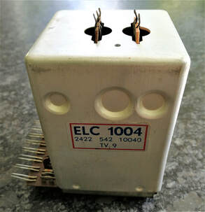
A unique ELC1004 tuner, the standard all-band B/G version. [Oswald Moonen collection]
|
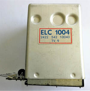
Clearly the Elcoma-specific 12nc is visisble: 2422 542 10040. The code TV9 is probably the Valkenswaard production code.
|
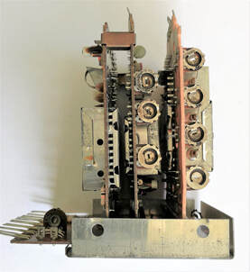
Internal view of the ELC1004 with the protective can removed. From left to right the vHF-I, -III and UHF sub-PCBs. Note that the two VHF panels are clamped together.
|
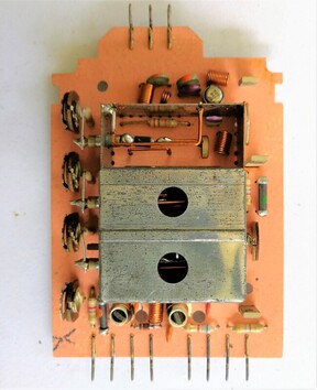
The UHF PCB, two sections covered by metal shielding. On the left side 4 potmeters for varicap pre-setting.
|
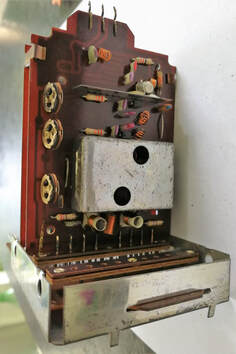
The VHF-III PCB with only two transistors.
|

The VHF-I PCB, which also contained the IF amplifier common to all three bands. Note the external biasing transistors.
|
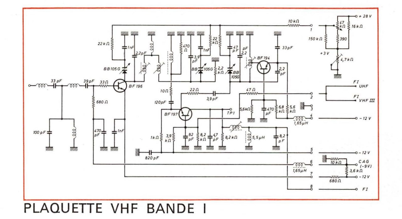
|
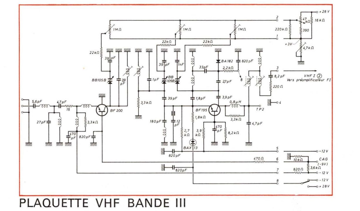
|
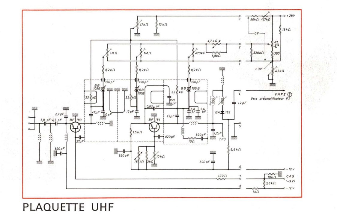
The three circuit diagrams of the French version ELC1054. Note the many alignment potmeters. [Philips RTC (La Radiotechnique-Compelec) - Guide de l'ingenieur - Radio, Télévision-Musique - 1970]
However innovative the concept may have been, as far as I can see it wasn't very successful from a business perspective. TV sets using these tuners are very difficult to find. Despite the fact that they were initially broadly advertised in the Elcoma Data Books, although eventually for only one edition (1971/72). The reason for this can only be guessed, but a likely one is that the 3rd party potential customers were suspicious of tuners that were not used by Philips themselves. "Are you trying to sell us the stuff that Philips itself doesn't want to use?", a reaction heard more often in the TV-related component domain. Additionally, production of the ELC1000 was quite a nightmare. Because of the large varicap spreads alignment was often impossible, requiring replacement of components for a next trial. Typical production levels in the Valkenswaard factory where 100 units per day, insufficient for real volume production. But whatever the reason, the life of the first ELC1000 generation was short, and only one application was actually found: an ELC1034 in a Philips Monza TS7 B&W chassis. However, given that it was produced in at least two factories this suggests it sold in some quantities, most probably to external UK and Latin American set makers.
|
There were 4 basic ELC1000 types: ELC1004 (standard B/G), ELC1024 (Italian channels), ELC1034 (Italian channels and IF) and ELC1054 (French IF). Due to the modular approach each type could then be ordered in multiple versions, I'll use the 1004 as example: VHF I-only (ELC1000), VHF-III-only (ELC1001), VHF I & III with base plate and can (ELC1002), UHF-only (ELC1003), all-band with base plate and can (ELC1004), and VHF I & III without base plate and can (ELC1005). With the four types this made in total 24 versions!
A real 1970 psychedelic style TV components data book of the French Elcoma branch RTC La Radiotechnique-Compelec. It contained quite some details on the ELC1000 family.
|
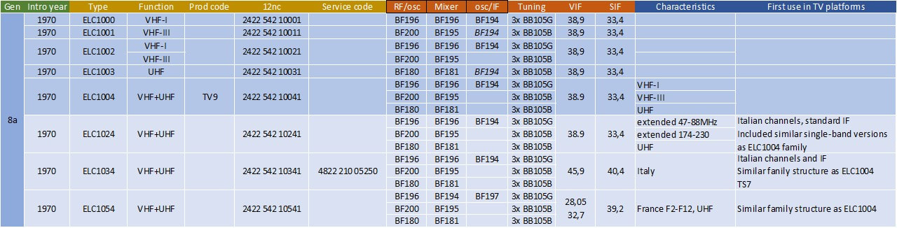
Overview of the Philips ELC1000 family of modular tuners. Each type was available in 6 versions, which have only been detailed for the ELC1004 type. Note the 12nc's: 24= Elcoma, 22= Netherlands, 542= tuner Eindhoven, xxxx1= the ELC type number.
12ET5672-12ET5632 or VD1-UD1, 1972
The next generation tuners, although not as mysterious as the V6-U6 and V7-U7, is still not entirely transparent. It seems that after the two diverging "experiments" of the KD1/KD2 (multiple sub-PCB's inside a single can cover) and the V6-U6 (two separate smaller but not identical tin cans) the company went back to a more aligned approach, combining the lessons from both. In the new concept two separate modules were used like in the V6-U6, but plugged into a common socket and of equal size in comparison with the KD1/KD2 and ELC1000. The new tuners were launched in 1972 together with the introduction of the 3rd generation CTV called K9. They were called 12ET5732 or VD1 (the VHF tuner) and 12ET5632 or UD1 (the UHF tuner). Initially I thought these names only referred to the Krefeld versions of the tuner, and that there were separate Eindhoven versions, but now I'm fairly convinced that there was only one tuner. The main arguments for this are:
- Dimensions, pinning and application of the VD1/UD1 and the supposed "Eindhoven version" are 100% identical;
- While there is ample photographic and sample evidence of the VD1/UD1, I haven't found a trace of a different version;
- Of the VD1/UD1 I have only 12nc's and no Service 12nc's, while for the "Eindhoven tuner" it is the reverse. With multiple codes this can not be a coincidence, and I simply conclude they refer to the same tuner.
|
The names VD1/UD1 (where I suspect the D stands for "Deutschland" (Germany) , like in the KD1/KD2) indicate their German, so Krefeld, origin. Electrically major innovations were implemented in the VD1 and UD1:
VHF
|
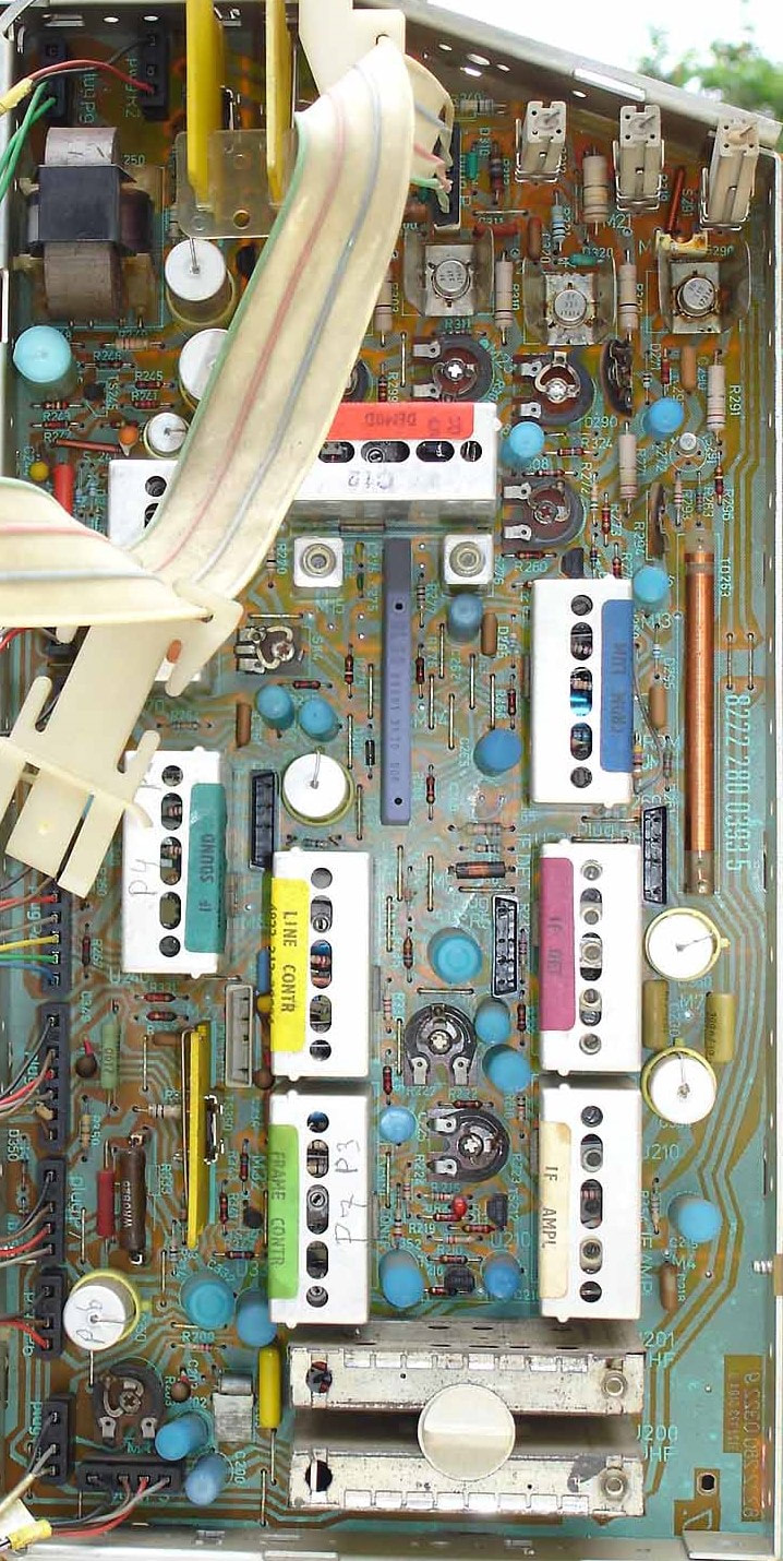
This is how the VD1 and UD1 appeared in TV sets: for the first time no longer on a separate sub board, but mounted directly on the small signal panel, with the two tuners fixed in the socket using a large plastic screw. The VD1 above, the UD1 below. The tuners are directly next to the IF amplifier and detector module on the right. This is the very first K9 set X26K201, from 1972. The modules with coloured labels for IF, sound and chroma, often contained the first ICs used in this set, from the TBA500, 600 and 700 range (and TCA for Secam). [Marcel's TV Museum]
|
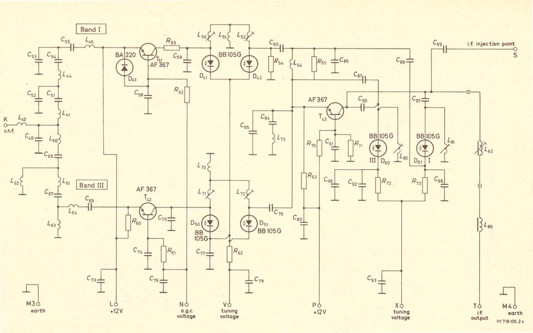
The Philips 12ET5732 VD1 VHF tuner.
[Elcoma Data Book CM3, June 1973]
|
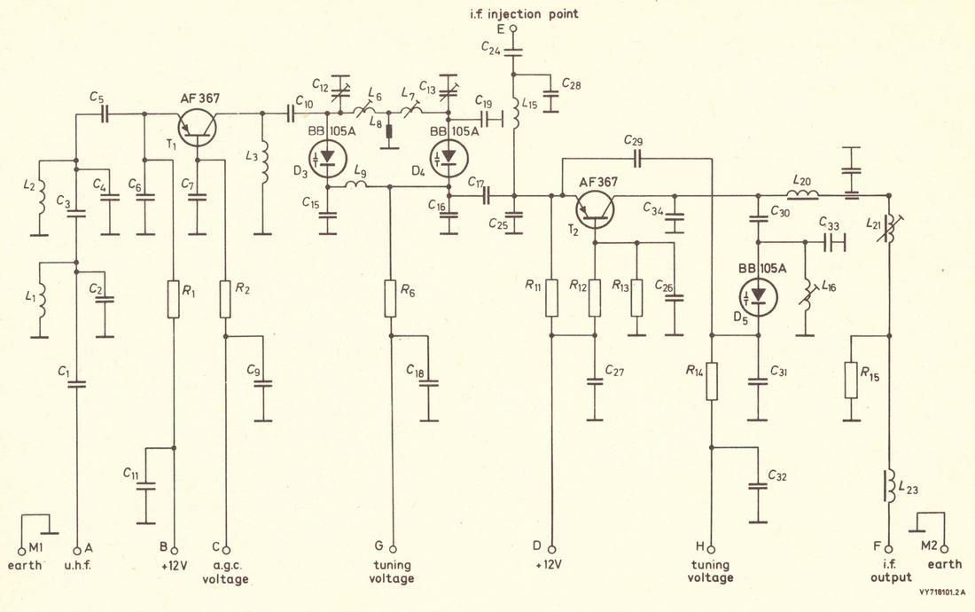
The Philips 12ET5632 UD1 UHF tuner [Elcoma Data Book CM3, June 1973]
|
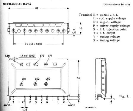
Mechanical drawing of the VD1. The RF input is on the right (pin K), the IF output on the left (pin T).
|
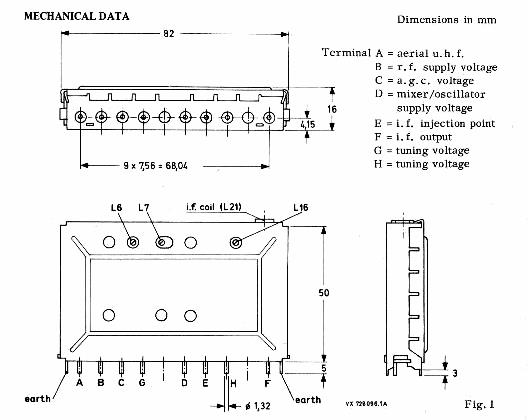
Mechanical drawing of the UD1. The RF input is on the left (pin A) and the IF output on the right (pin F).
|
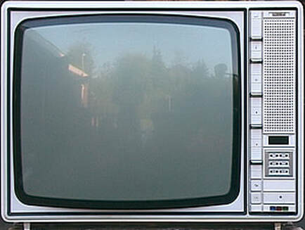
The television chassis that introduced the VD1 and UD1, the K9 from 1972. This is the X26K206. Lower right the 6 tip touch channel select buttons with above it the Nixie-tube channel indicator display. [Marcels TV Museum]
|
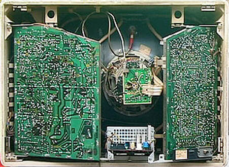
The rear view of the same K9 X26K206. Almost all electronic components have now been mounted on two separate panels that swivel out for easy access. Left the high voltage and convergence panel, right he small signal panel with lower right the antenna connector opposite the VD1 and UD1 tuner modules on the other side. [Marcels TV Museum]
|
|
The mechanics of these tuners introduced a number of new features, as already introduced above.
The VD1 and UD1 tuners were introduced in the Eindhoven-designed K9 CTV platform, as well as the portable and smaller screen size KT1 and KT2 chassis. It was last used in the high-end Super de Luxe version of the next K11 CTV chassis. The Krefeld TV factory used the VD1/UD1 in the German chassis K9D, K9i and K11 as well as the E1 B&W portable TV platform. It seems that the UK G8 and G9 chassis stuck with the U6 tuner and never migrated to the UD1, while the French organisation developed its own tuner. 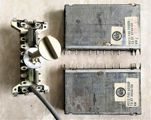
The Philips 12ET5632/02 or UD1 (bottom) and 12ET5732/02 VD1, both of them proeduced in Krefeld (code KR). Note the mirrored construction, e.g. the position of the IF alignment coils on the right sides. On the left the socket for both tuners, with the RF antenna cable and the fixating screw. These samples were produced in the Elcoma period of tuner manufacturing, when the German products received 12nc's 9012 74 followed by the product name. [Ite Weide collection]
|
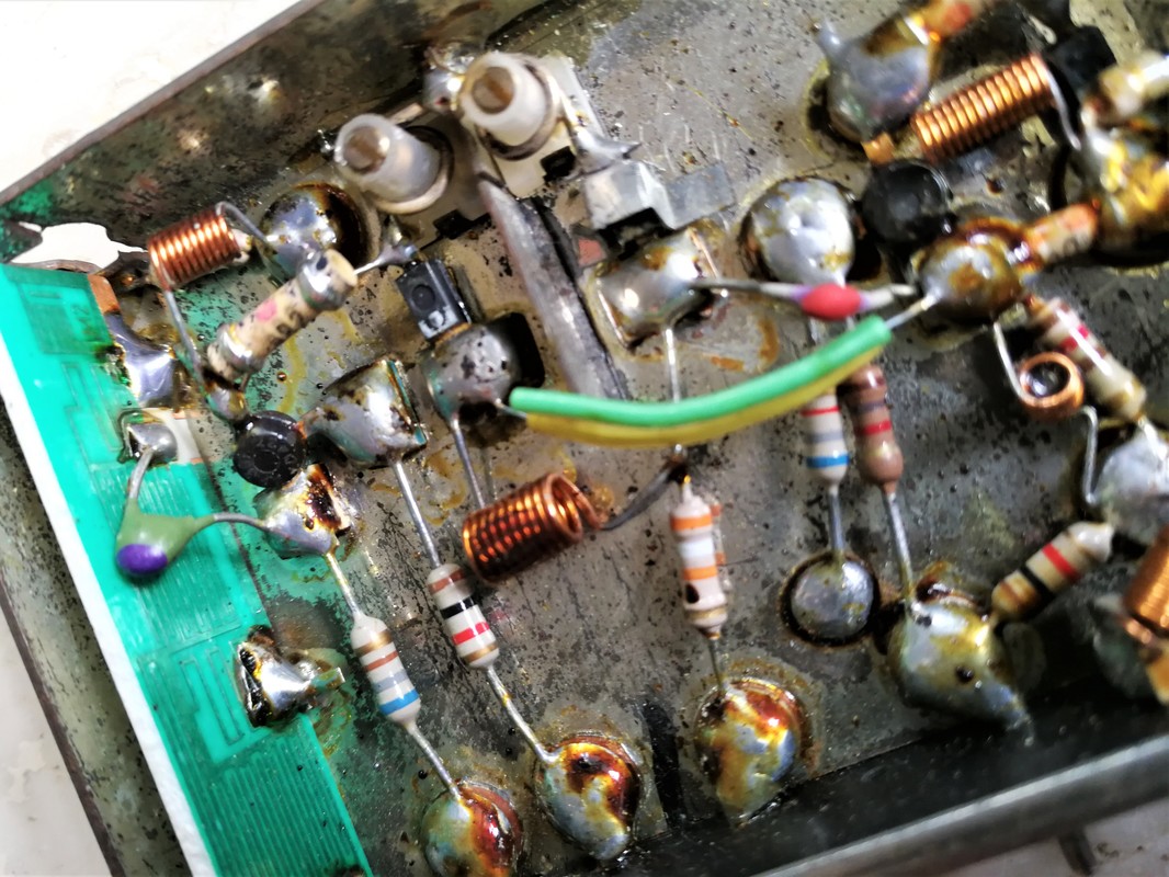
Interior view of the UD1 12ET5732/02, showing the isolated soldering "islands", and on the left the (probably) ceramic input filter board. [Tuner Ite Weide]
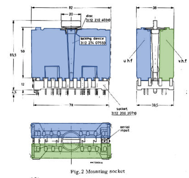
Drawing of the mechanical assembly of the two tuners on their common socket. [Philips Elcoma Data book CM-3, June 1973]
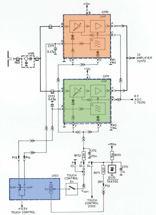
Typical application diagram of the VD1 (green) and UD1 (orange) in a KT2 chassis. Because there is no longer need for selection between VHF-I and -III the blue channel pre-set module (blue) has been substantially simplified. [Philips 14C825 Service Manual on Radiomuseum.org]
|
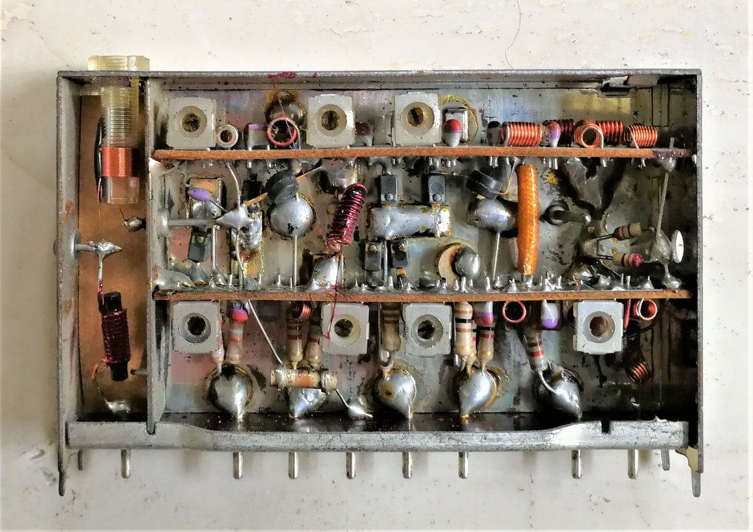
Interior view of the Philips VD1 12ET5732/2 VHF tuner. Note the 2 sub-PCBs, one for each VHF band. [All pictures Ite Weide collection]
|
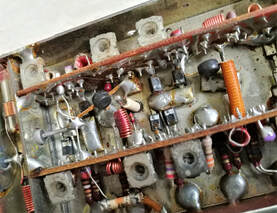
Close-up of the internal construction of the VD1. Note the "free-hanging" MO transistor.
|
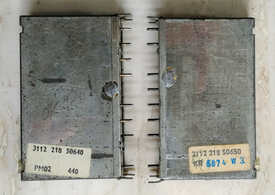
A pair of Philps UD1 (left) and VD1 (right) tuners. These were produced in 1974, the post-Elcoma period, when the products received Video-codes again (3112). Note that the UD1 is produced in Monza (PM), the VD1 in Krefeld (KR).
|
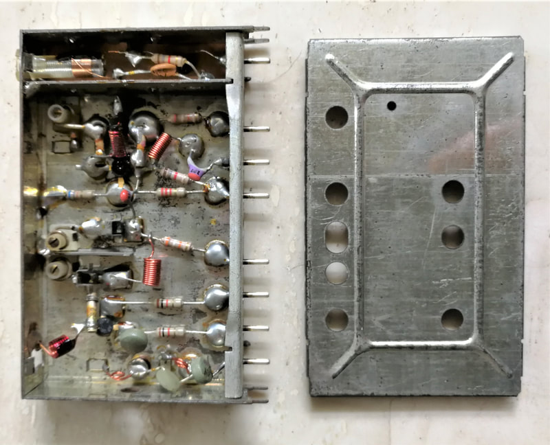
The Philips UD1 (3112 218 56440) UHF tuner with cover taken off. The cover could be used for both VD1 and UD1, with the alignment trafos properly aligned to the cover holes. [Ite Weide collection]
|
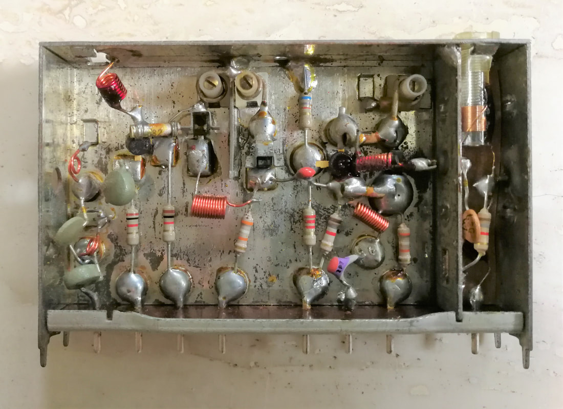
Detailed interior view of the UD1. The two transistors and the soldering islands are clearly visible.
|
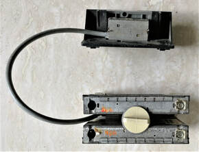
A set of Philips VD-UD1 mounted on their common socket, including the RF cable to the antenna connector assembly.
|
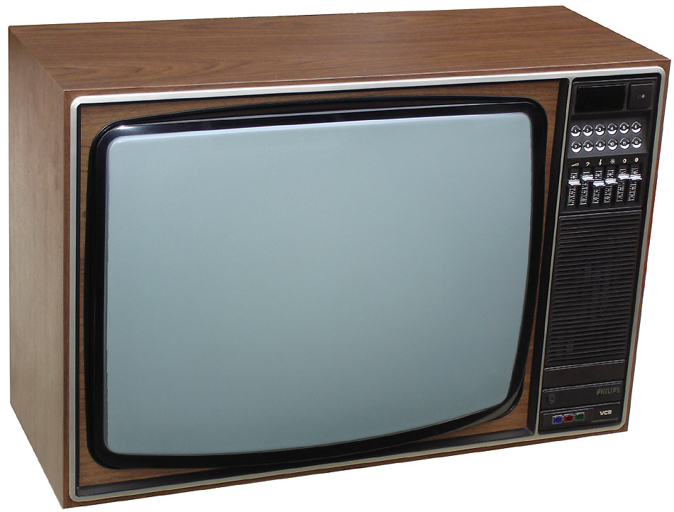
The Philips K11 colour TV chassis. This is the 26C565 from 1975, the first K11 model. It still used the VD1-UD1 tuners. Note the new 12 tip touch channel selection buttons. [Marcels TV Museum]
|
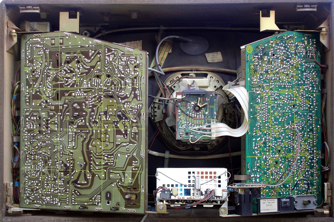
Rear view of the Philips K11 26C568 from 1976. The general construction is identical to the predecessor K9. [Marcels TV Museum]
|
The next tuner to be introduced is a typical intermediary type, the V311. It introduced the new frame and technology of the next generation V300/U300, but was pinning-wise backward compatible with the VD1. I will thus treat the V311 as part of the VD1/UD1 generation. From 1975 we thus see the V311 replacing the VD1 in the later K11 chassis, still in combination with the UD1 and mounted on the common block with the large screw. The V311 re-introduced the VHF-I/III band switching. Probably the concept of the single tuning voltage for band I and III as used in the VD1, each using only a portion of the tuning voltage range, was integrally not better or cheaper than the more classical switched band concept. Also because the smaller tuning voltage range per band made the tuning steepness higher, and the tuner thus more prone to non-linear behaviour. So essentially the V311 went back to the BPF and oscillator tank switching concept used in the KD2, with switching diodes increasing or decreasing the inductor values. The two-transistor architecture with a single RF pre-amp and self-oscillating MO was maintained from the VD1.
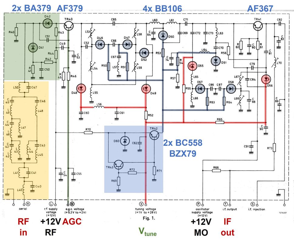
Circuit diagram of the Philips V311 VHF tuner from 1975. Yellow is the PCB input filter module, green the AGC function, red the regular varicap tuning circuit and blue the automatic band I-III switching block and control. [Philips Elcoma Data Book CM3a, September 1978]
|
The V311 contained two interesting new circuits.
|
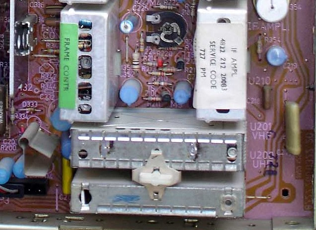
The first appearance of the V311, here seen in the Philips K11 26C568. The lower UD1 still has the original soldered back side, the V311 shows the two spring-clamped new covers. [Marcel's TV Museum]
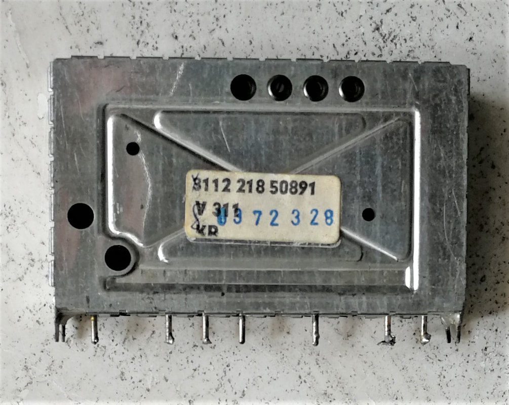
The V311 also introduced a new cover design, with a different position of the alignment holes. Pinning was compatible with the VD1. [Collection Oswald Moonen]
|
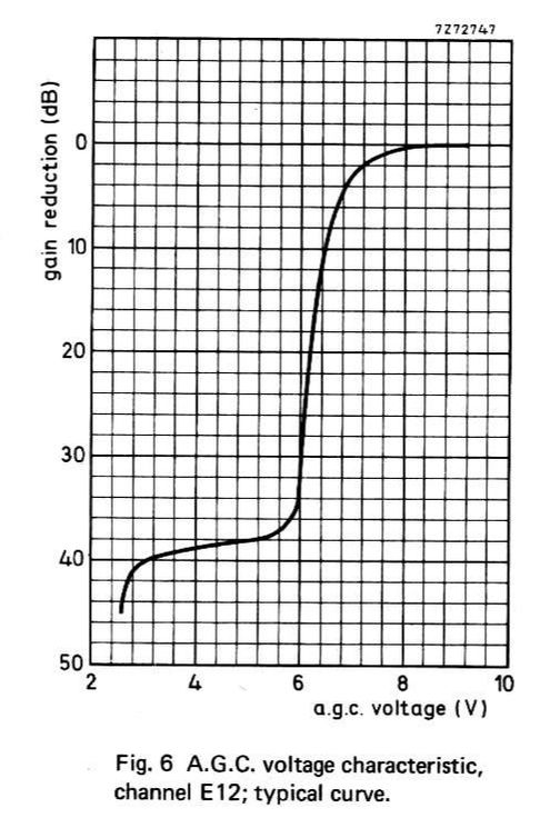
The typical voltage-driven AGC curve of the V311. The first part between 9,2 and 6V is probably due to the PIN diodes, the lower part due to the reducing emitter current. [Philips Elcoma Data Book CM3a, September 1978]
|
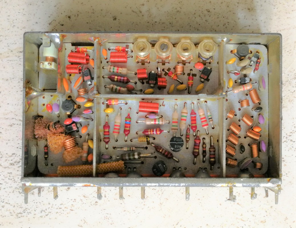
Top interior view of the V311. On the right the input chamber with the filter and matching. At the top the pre-amp with the two PIN diodes nearby. In the lower central chamber the biasing, including the 2 BC558 transistors for the band switching. At the top the BPF, in the left chamber the LO. [Collection Oswald Moonen]
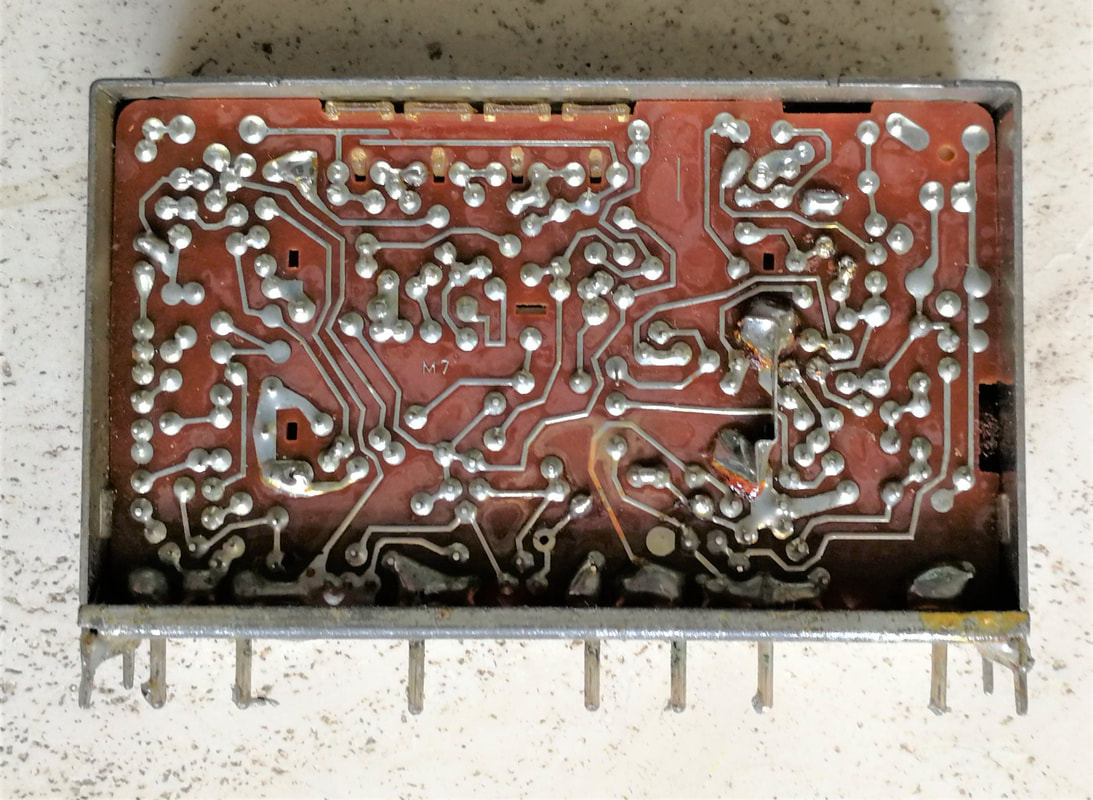
The bottom view of the V311, showing the PCB soldering side.
|
As can be seen from the pictures, the V311 also introduced a number of not insignificant mechanical and constructive innovations:
- a single printed circuit board (PCB) for the entire tuner, with all soldering on one side (the back) and all components on the upper side;
- all components wired, and inserted properly into the PCB holes. No more components hanging in the air;
- the majority of inductors are now small wire-wound air coils. Only four remaining alignment inductors are small trafos;
- solid internal shielding walls, providing mechanical stability, good shielding and solid electrical grounding. This divided the tuner into clear functional chambers: input-BPF-DC and control-LO-IF output;
- a separate pin-holding PCB at the bottom, so no longer feed-through capacitors. Therefore thicker and more robust pins were allowed.
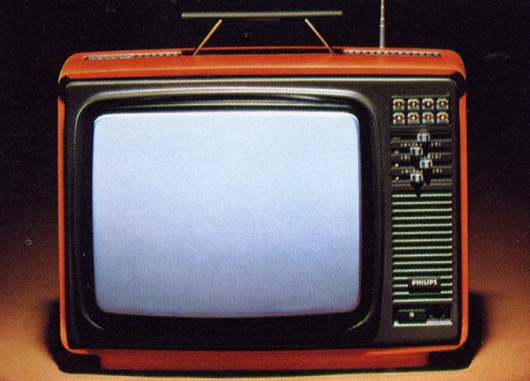
The VD1-UD1 tuners were also used in the portable CTV chassis KT2. This is the Philips 14C625 Philetta Color 625 from 1976. [RadioMuseum.org]
|
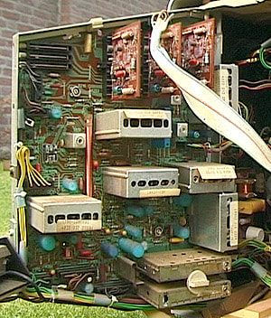
The KT2 portable CTV chassis re-used most technologies from the larger K11. The VD1 and UD1 are clearly visible lower right. [Marcels TV Museum]
|
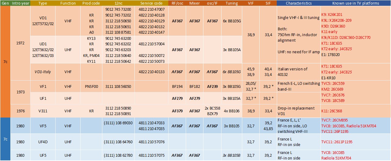
Overview of the VD1-UD1 family of Philips varicap tuners, mostly used in CTV chassis (red, black is B&W). Initially they were under the Elcoma division (indicated by 12nc starting with 90), later they moved back to Video (12nc 31). All transistors are PNP (bold). The V311 is included because of its pin-compatibility with the VD1. The blue part of the table covers the French versions of the tuners.
French tuners 1965-1985
Due to the quite different French TV standard (CCIR system-E), French tuners have always been different too. In this context we will not look at the Belgian multi-mode sets, essentially standard Western Europe sets that were modified to receive the French standards and the associated Belgian derived standards (CCCIR-C for Flanders, CCIR-F for Wallonie). These have been covered as part of the regular tuner families. French TV's and tuners were designed primarily to receive the French standards, with the possibility to receive RTL Luxembourg (system F), German/Swiss/Italian (system B) channels in the border areas. In practice the latter was seen much less, but in the entire north of France reception of Luxembourg - which used a very powerful transmitter - was standard. Most French sets up to the mid 1960s thus received standards E and F. In these sets the reference was the sound IF of 39,2MHz, resulting in picture carriers at 28,05MHz (E) and 33,7MHz (F). This was the standard French tuner arrangement. I know of one French TV (the TF2370/120) for the Elzas/Swiss border area, with the capability for CCIR-B reception. This used 37,7MHz for the Vision IF, almost certainly because in this case the N+1 sound-IF notch filter appeared at 39,2MHz, the standard E SIF.
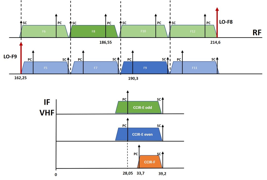
|
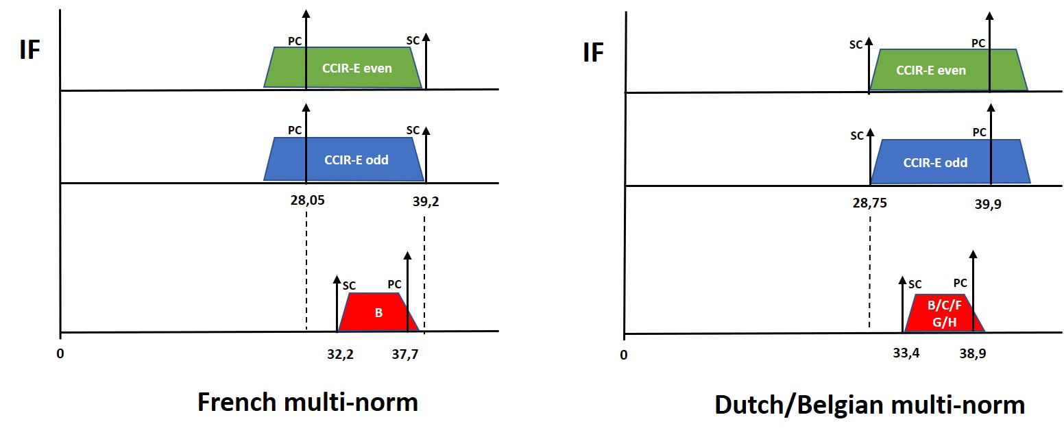
Left, the standard French IF arrangement for standards E and F reception. Above the comparison between French multi-norm arrangement, on the right the typical Belgian multi-norm set-up.
|
With the emergence of UHF it all became more complicated. Although France continued to go its own way with SECAM colour, on channel arrangement it started to comply with the wider European approach. So French system-L on UHF used the same 8MHz channel width, albeit with 6,5MHz VIF-SIF distance vs. the normal 5,5MHz. The SIF of 39,2MHz continued to be the reference, such that the new system-L VIF became 32,7MHz, a modest modification of the 33,7MHz of Luxembourg. Despite the different and inverted IF arrangement of system L (32,7-39,2MHz) vs. the standard European system G/H (38,9-33,4MHz) the UHF tuner could be re-used because of the identical 8MHz channel width and the relatively wide UHF bandpass characteristics. Quite quickly after the start of system L on UHF it was also introduced on VHF-III odd channels, with exactly identical characteristics. Which meant, as opposed to the "standard" solution in Europe, 8MHz channels in VHF, oscillator-low arrangement and SIF-above-VIF. In practice many receivers received L-on-VHF in the system E mode without modifications, other than the adapted SIF. Despite the much wider filtering this apparently gave acceptable images.
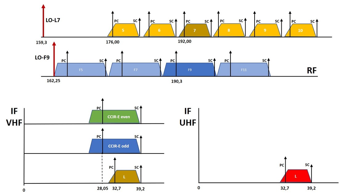
|
On the left the arrangement as the French tuners were by the early 1970s, with the new system-L being rolled out in UHF and VHF. This was also the concept in use when Colour TV was introduced in 1966 with the TVC3 chassis, which still used a drum valve-based VHF tuner (V5B) and the first transistor UHF tuner (U5P). It was replaced by the UV1 tuner with unchanged IF settings in the TVC4.
These settings remained unchanged on the TVC5, a platform that used French-modified versions of the V7-U7 first, later moving to the VF1-UF1 French versions of the VD1-UD1. Of these tuners the mechanics were identical to the VD1/UD1, using the same base plate and antenna connection via a pin. The UF1 was 95% identical to the UD1 design, with probably slightly larger bandwidth for system L. The VF1 required special provisioning for switching between the odd/even VHF-III channels, which will be explained further down for the VF5 successor. |
Of course all first generations French CTV chassis (TVC3-4-5) were SECAM-only, and the associated tuners were also uniquely specified for the French standards. Gradually, however, PAL seeped in for the reasons given above, and French CTV chassis gradually became multi-norm. Interestingly, this had no real effect on the tuners, because the L channel bandwidth was equal to the G/H channel width and the VIF-SIF distance higher (6,5 vs. 5,5MHz). In other words, a system-L tuner could always receive systems B/G/H and no special tuner was required; LO high/low and IF setting would be taken care of in the software. At the same time the French tuners remained specified for the French norms only, although they were used for B/G/H too.
|
The next thing that happened was the introduction of SAW filters for IF filtering. This meant that no longer the sound IF was the reference, but instead the Vision IF, which had to match with the SAW vestigial side band filter flank. Starting from the V5F tuner for both E and L systems the VIF became 32,7MHz, which meant the system-E SIF extended to 43,85MHz. For UHF this had no effect.
In the meantime the use of system E and its Belgian/Luxembourg version F was steadily declining. Belgium/Wallonie switched off F in 1968, moving to 625 lines PAL, as did Luxembourg RTL in 1971. But even in France TF1, the main broadcaster on VHF-E, increasingly moved to system L 625 lines on UHF, albeit using SECAM (of course). |
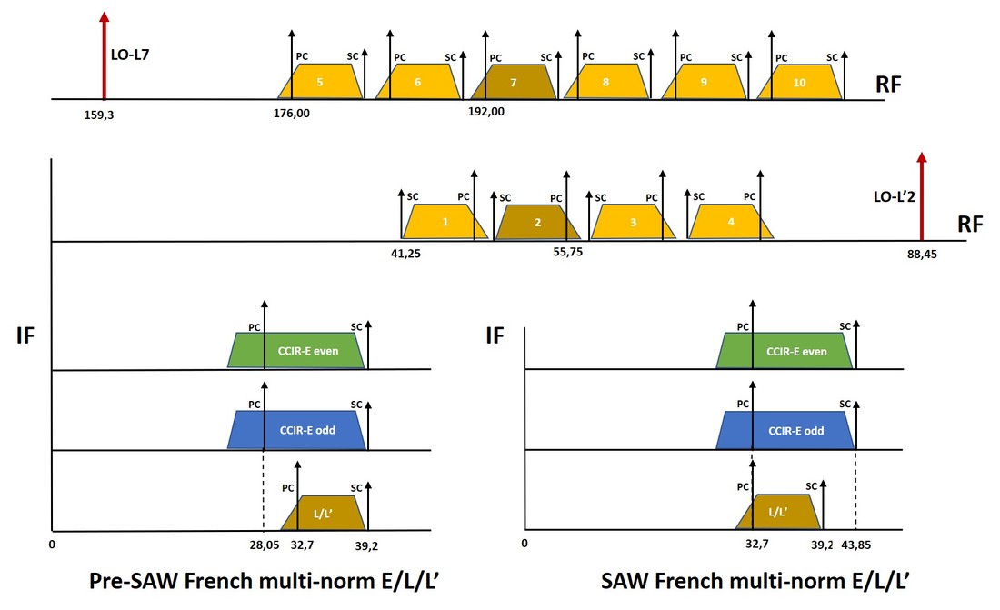
French channel arrangements in the period from system E 819-lines to system L/L' 625-lines only transition. From top to bottom: VHF-III L channels, VHF-I L' channels, IF arrangements (left pre SAW filters, right with SAW filters).
|
|
December 1979 the French government issued a decree that all TV's required a mandatory SCART connector (in French Péritel for Périferie de Télévision) to connect TV's to other devices like Video Recorders or satellite decoders. In parallel it mandated the extension of system L into VHF-I. Since all French CTV's used oscillator low and thus VIF-below-SIF, this didn't work in VHF-I. (The LO-frequency for channel 1 would have been 41,25-32,7=8,55MHz). As a consequence, in this band the channels were inverted, with PC high and oscillator high. Since all other parameters remained identical to system L this was referred to as system L' (L-prime). From 1980 all French sets and tuners were thus L/L', in case of multi-mode extended with B/G/H without influence on the tuner. Then, March 1981, the French government of Président Miterrand - the same who as minister of economic affairs had pushed through the 819-line standard in 1951 - issued a décret that TV sets were no longer required to support system E, thus effectively killing it. Set makers like Philips immediately dropped all 819-line capability on most of their sets as a measure of cost reduction. This happened in the midst of the TVC7 and TVC8 chassis life, both of which nevertheless immediate switched to 625 lines-only, although mostly SECAM/PAL multi-mode.
|
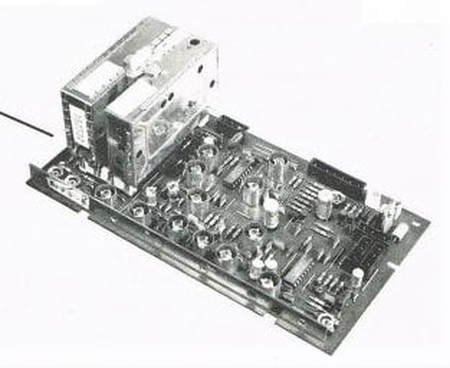
The UF5 and VF5, seen here on the official picture of the TVC8 chassis IF panel. These tuners were the first to introduce the fixed picture carrier IF at 32,7MHz. Note the continuing use of the common ground plate with fixation screw on top. [Philips TVC8 Service Manual]
|
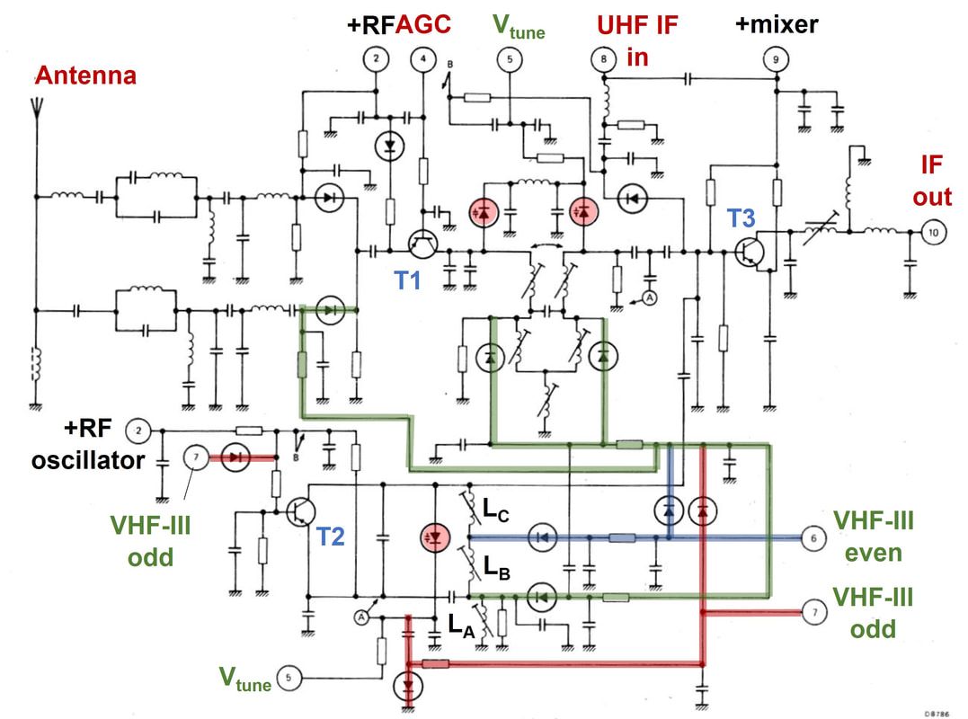
Circuit diagram of the Philips VF5 VHF tuner with VHF-III odd/even-switching for the 819-line System E. Green switching paths are for both VHF-III modes, red for the odd channels and blue for the even channels. [Philips Elcoma Data Book CM-2, December 1982]
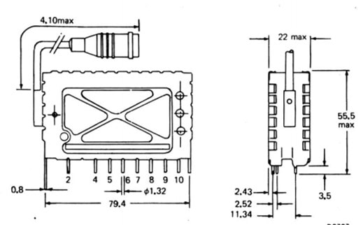
The VF5 and UF5 were the first tuners in this family where the RF input pin was moved to the side. For these French tuners the coaxial 75Ohm cable and connector were factory-mounted. [Philips Elcoma Data Book CM-2, December 1982]
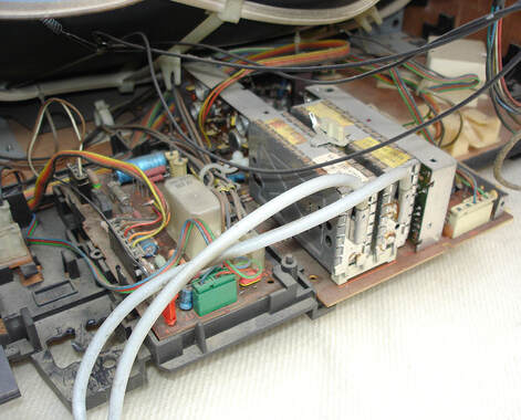
The Philips VF5 and UF5 inside a 1981 Philips-produced Radiola multi-norm set, the 51KM704, based on the TVC8 chassis. Note the pre-mounted RF cables. Both the tuners and the set were produced in Dreux, France. [Marcel's TV Museum]
Subsequent generations, UVF10 and UVF14 followed the U300/V300 and UV400 form factors. One specific characteristic was that they were delivered with the RF cable and connector already attached, see the mechanical drawing.
Another interesting tuner-related feature of he French SECAM televisions was the "Ligne magique" or Magic Line tuning indicator. On the one hand this was probably required to allow the required accurate tuning of especially the AM sound IF within its narrow BPF, given that AM is more sensitive to de-tuning than FM. At the same time it offered a nice feature for the user when installing channels. When the drawer with the channel pre-set switches and pot-meters was opened, the AM sound AGC peak detector output was translated into a white vertical line superimposed on the picture. The better the reception, the more the line moved to the right. This feature was introduced with the first TVC3 and remained standard as long as SECAM was used till the early 1980's. |
Just before the end of the 819-line norm the VF5 anf UF5 tuners were introduced, the French versions of the new 300-family. They were the first versions to introduce the RF input on the side of the tuner, no longer on one of the pins. To guarantee good RF performance and input matching a length of coaxial cable with phono connector were pre-soldered to the tuner. Again the UF5 is roughly identical to the UF1 and the UD1. Most interestingly is the VF5, the last system E 819-line tuner. It is a typical French tuner with the picture carrier IF low at 32,7MHz (resulting in sound IF at 39,2MHz for B-G-H-L and 43.85MHz for System E). This meant that for the odd channels (RF Picture low) the LO had to be below the channel, while for the even channels the LO had to be above the channel. To this end the tuner had separate VHF-III odd and even selection pins, which switched the oscillator arrangement. In VHF-I the tank circuit inductor was highest, formed by La, Lb and Lc in series. For VHF-III odd (LO below the channel) La was by-passed using a switching diode (green connections). When receiving VHF-III even channels (blue connections) also Lb was by-passed, thus reducing the tank inductor to only Lc. All in all this tuner required 3 transistors, 3 varicaps and 12 switching diodes!
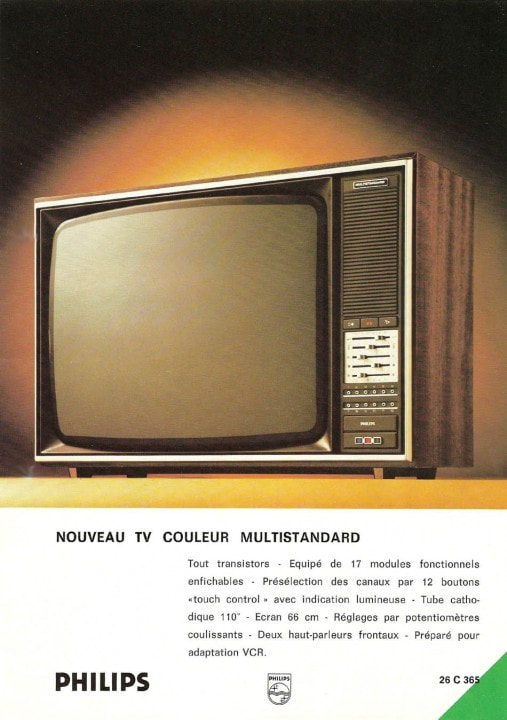
The Philips 26C365 TV from the KM2 multi-mode chassis around 1975. It still supported seven different 625/819-line and PAL/SECSM norms. It used the V7M and U7 tuners.
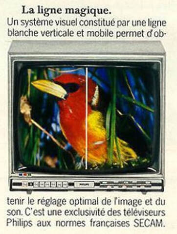
|
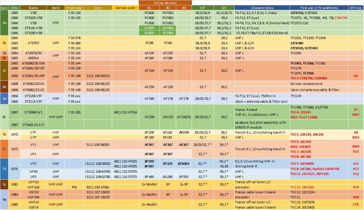
Overview of the tuners used in French TV chassis, from the introduction of UHF and CTV mid 1960s to the last tuner that was not part of the normal Philips tuner families. Although in the formal documentation all tuners are specified for French standards only, all tuners marked with an asterisk (*) in the VIF and SIF column were capable of receiving PAL B/G/H too. Although due to the SECAM system all French chassis had a lot of local development in Suresnes/Dreux, the last column gives a rough indication of the Eindhoven chassis on which they were based from a technology and key component perspective.
UK Tuners 1964-1984
Like France the UK was suffering from its old, UK-only B&W TV standard: the 405-line CCIR standard A. It is thus no surprise that the UK eagerly jumped on the opportunities offered by the availability of the UHF band. Probably having learned its lessons on a total standard-Alleingang, there was now much more willingness to align with the larger European and CCIR standardization: 625-lines, negative video, FM sound, 8MHz channel width and later PAL colour. But whereas the countries that had been using VHF CCIR-B (the good old "Gerber-norm") for compatibility reasons more or less had to stick with 5MHz video bandwidth and 5,5MHz picture-sound carrier distance, the UK - as was France - was not hindered by such history and chose to optimize its UHF parameter settings. For the highest picture quality thus 5,5MHz video bandwidth was selected, in combination with a vestigial side band of 0,75MHz. This gave a similar picture quality as the French (CCIR-L) and Eastern European (CCIR-K) solution of 6MHz video bandwidth and 6,5MHz picture-sound distance. These differences were technically modest, allowing essentially the use of tuners and other RF hardware identical to that used in the wider Europe too. The main consequences were found in the intermediate frequencies. The move to UHF was stimulated by transmitting the new channel BBC2 only on UHF. More importantly, the UK broadcasting authorities in 1969 decided that the country would move to a UHF-only system, making the old 405-line standard obsolescent although it took till 1985 to switch off the last 405-line transmitter.
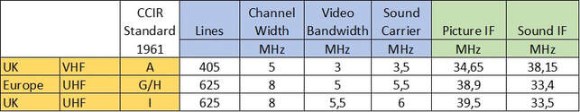
The old (CCIR-A) and new (I) UK TV standards, as compared to the standard European CCIR-G/H.
Because of the fundamentally different IF parameters for VHF 405 lines and UHF 625 lines, from 1964 British TV receivers in principle had to be dual standard. Initially this meant, like on the continent, that sets were still VHF-only but "UHF-ready", with retrofitting sets being offered. It seems two levels of upgrade sets were provided: sets that had already the multi-norm IF, video and sound processing built-in only required the AT7530 set containing the AT6320 UHF tuner and the control knobs; NT2050 sets additionally provided a 6-valve IF panel as well as FM sound board.
Since multi-norm reception was new to the UK it mostly had to be re-invented. An interesting solution for the norm switch was the one from Decca, a Philips affiliate, which put a disk on the back end of the VHF drum tuner axis which, in the channel 13 position, operated the VHF-UHF switch on top of the tuner, which in turn operated a set of relays that drove the main system switch. Apparently it was not very reliable.
Since multi-norm reception was new to the UK it mostly had to be re-invented. An interesting solution for the norm switch was the one from Decca, a Philips affiliate, which put a disk on the back end of the VHF drum tuner axis which, in the channel 13 position, operated the VHF-UHF switch on top of the tuner, which in turn operated a set of relays that drove the main system switch. Apparently it was not very reliable.
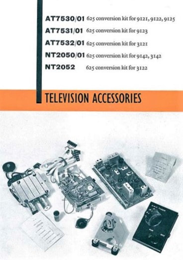
AT753x an NT250x UHF upgrade sets for British Philips TV's from the 1963/64 collection. On the far left the AT630 tuner with its PC88 and PC86 valves. [Philips UK 1963 catalogue via TVNT.net]
|
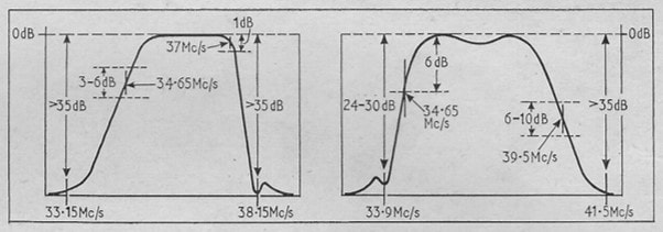
Real 405/625 multi-mode TVs didn't live for long, quickly being replaced by 625 lines only sets. These are the IF curves of the Philips B&W G23T210, using the AT7672/20 UV1 tuner. [Philips G23T210 Trader Sheet 1868/T350]
|
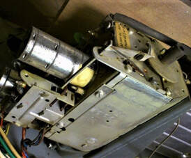
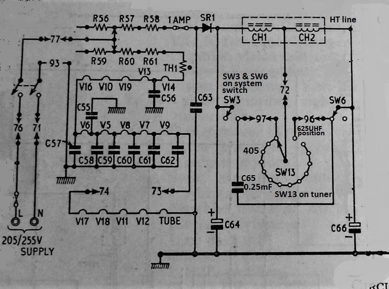
The new UK IF for CCIR-I
|
One of the consequences of the still UK-only situation with UHF system I was that a dedicated IF was selected: 39,2MHz picture carrier, 33,5MHz sound IF. Because CCIR-I uses a larger PC-SC distance as opposed to the continental B/G/H norms (6 vs. 5,5MHz) the distance of N-1 SC to N PC is smaller (1,5 in stead of 2,5MHz). Apparently it is better for overall system performance to have the LO closer to the N+5 PC than the N+4 SC. (B/G/H with 38,9MHz has the LO 1,1MHz from the PC and 1,4MHz from the SC). So the CCIR-I LO was placed 0,5MHz from the PC and 1,0MHz from the SC, resulting in a VIF of 39,5MHz. It was almost certainly no coincidence that now the unwanted N-1 SIF fell exactly on the channel A1 sound carrier. The steep sound filter would thus also filter this major interferer in the larger London area.
|
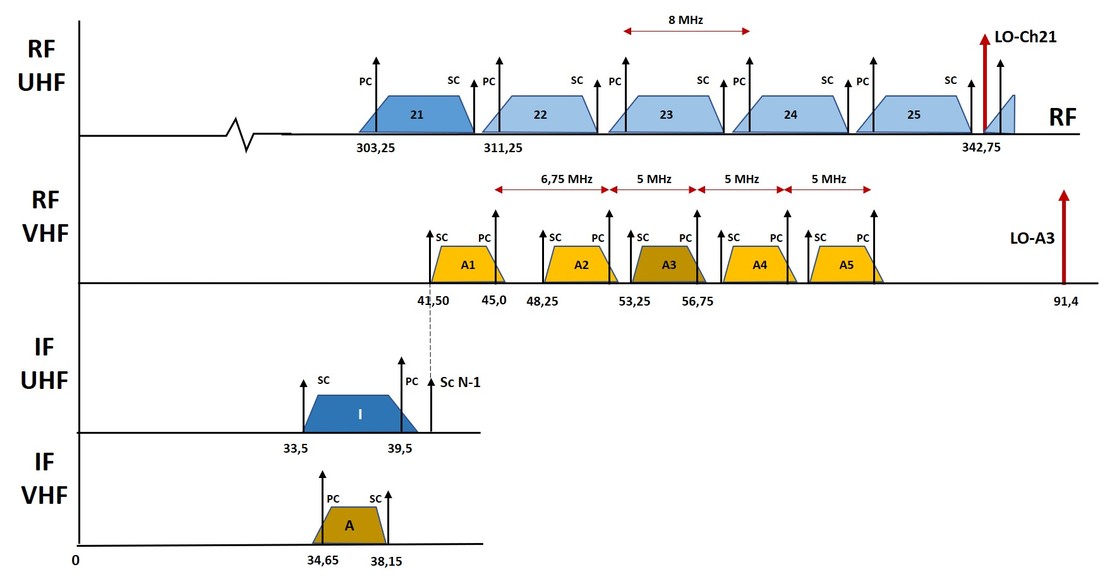
The RF, LO and IF arrangements for the old 405-line CCIR-A (yellow) and new 625-line CCIR-I UK TV broadcast norms. Note the unique location of channel A1 (Alexandra Palace) as opposed to the other A-channels (6,75MHz channel spacing vs. 5MHz); the fact that the UHF LO is exactly in between channels; and the fact that UHF N-1 sound is exactly on the A1 sound carrier.
|
|
Most tuners used in British Philips sets were in principle the tuners coming from Eindhoven. Unlike the French organisation in Suresnes/Dreux, the Mitcham/Croydon tuner group did not change the mechanics nor the principal naming. The main changes implemented were of course related to the different IF, while the most noticeable design influence was the use of different transistors. So whereas the Eindhoven and especially the closely linked Krefeld design teams continued to rely on germanium transistors and later their silicon equivalent PNP successors, the UK group was a leading user of silicon bipolar NPN transistors. In 1968 they introduced the BF180 to BF183 as UHF pre-amplifier and mixer-oscillator and VHF mixer and oscillator, respectively. The UHF AT6381/20 U5 and VHF/UHF AT7672/20 UV1 were the first to use them in the G6, the first Croydon-developed CTV platform derived from the Eindhoven K6. The U6 tuner was introduced together with the next generation BF262 and BF263 silicon RF transistors in the G8, the first CTV platform to no longer support the legacy 405-line norm. From now on all UK sets would be UHF-only! The U6 tuner was very successful and lived for two complete CTV generations, the G8 and G9.
Because of the standards harmonization the differences between continental chassis and UK chassis became very small, the G11 was the last chassis to be developed in Croydon. From now on also the UK market would use versions of the centrally designed chassis, which became increasingly flexible towards multi-norm reception due to the growing use of ICs. The G11 introduced the U321, the last one of which there is a Croydon-designed version; all tuner designs now came from Eindhoven. In parallel Philips Elcoma sold the ELC1043 on the UK market, but only to third parties (and often Philips affiliates) Decca, Thorn and Pye, while the ELC2003 UHF-only version was used in the KT3. |
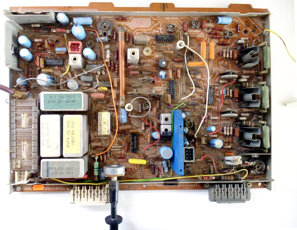
The Philips U6 tuner on the IF panel of the UK G8 chassis, model G26K536. [VRAT2 Forum]
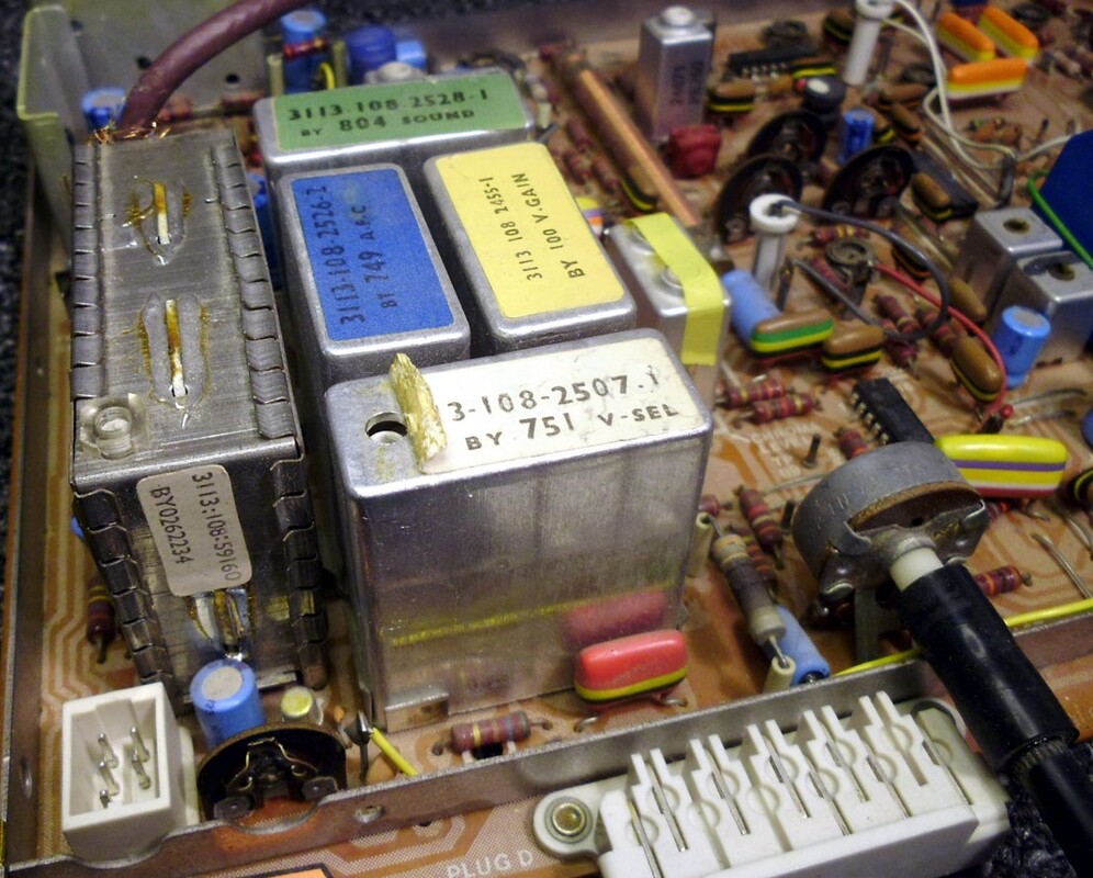
The same U6 tuner on the G8 IF panel seen from the side. The 12nc starting with 3113 indicates a Croydon design, the production code BY02 indicates production Dunfirmline. [UK Vintage Radio Forum]
|
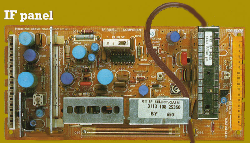
The Philips V321 UK UHF tuner on the IF panel of the G11 colour TV chassis. Dunfirmline production 1976, week 51. [VRAT2 Forum]
|
In the U300 family dedicated "UK tuners" continued to be developed, e.g. the U321, U341 and U343. Initially this meant current-driven AGC as opposed to the voltage-driven AGC of the standard tuners. (In the U321 a current reduction from 9 to 5,6mA provided minimally 26dB gain reduction, in the continental U322 a voltage reduction from 9 to 1,5V provided 30dB). The U321 also introduced the RF input on the side of the tuner, as in France, which would only be introduced in the standard tuners in the UV400 generation. Other than that the specifications seem to have been almost identical, so it is not clear yet whether there were any other items that made a tuner fulfil the (unknown) "UK requirements". A fact was, however, that like for the French CCIR-L UHF tuners the IF characteristics for CCIR-I were a super-set of the CCIR-G/H requirements; the 33,4-38,9MHz and 33,5-39,5MHz are identical from a UHF tuner bandpass perspective. The difference between continental and UK UHF tuners was thus rapidly disappearing towards 1980, and effectively the same tuner could be used for both, which is visible in the specifications in below table.
|
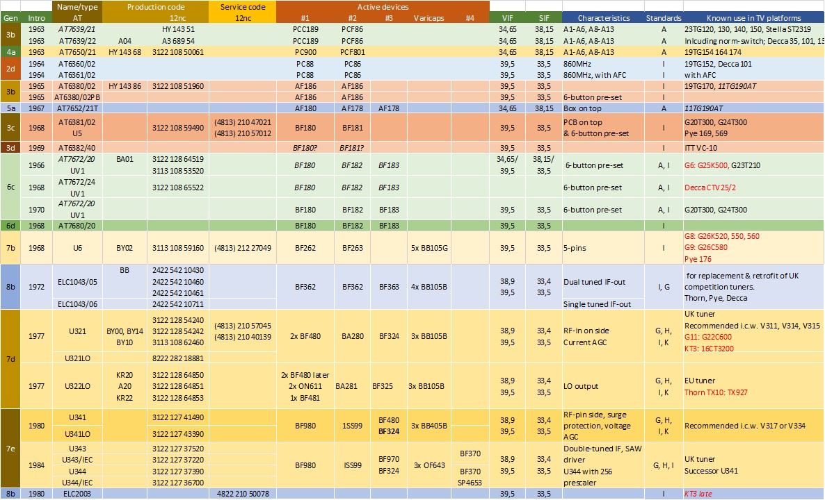
Overview of the Philips tuners used in UK TV sets between 1963 and 1984, showing the migration from VHF CCIR-A to UHF CCIR-I and the introduction of CTV.
The Tuner factories, 1965-1975
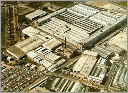
|
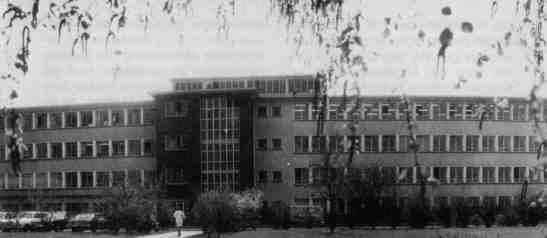
Two of the biggest Philips CTV factories; on the left Croydon, south of London, on the right the main administrative building of Fernsehwerk Krefeld. In both factories more than 3000 people worked, in at least two shifts. [Radiomuseum.org]
|
|
The tuner organisation essentially grew with its TV mother organisation and its factories. Still the principle structure was that every TV factory had its own tuner manufacturing. Krefeld remained one of the biggest tuner production centres, to the extent that in 1971/72 a dedicated production hall (Halle 4) was erected across from the already massive three TV production halls. Around 1966, with the introduction of CTV and the UV1 push-button tuner, production in the UK was shifted from Mitcham to the main TV fab in Croydon, while in 1972 a dedicated TV module fab was established in Dunfermline (Scotland, across the Firth of Forth near Edinburgh) that would produce the U6, U7 and U300 families for many years. In this period the Monza fab, focussing on low end CTV chassis, grew so much that the tuner production was pushed out, moving to a dedicated tuner fab in San Angelo, south of Milano in 1973. French tuner manufacturing continued in Rambouillet as before, while the Swedisch Norrköping TV factory obtained its tuners from Kopenhagen (Denmark). The Elcoma period also had its effect on tuner manufacturing, adding a new pool of factories. So between 1971 and 1973 we see tuner production in the Elcoma fabs Grâce-Hollogne (Belgium), Valkenswaard (Netherlands) and Stockton-on-Tees (UK).
The single exception to this trend was Eindhoven, still the central tuner development centre. TV production, however, had completely moved away from Eindhoven, mainly to Krefeld and Brugge, and tuners were increasingly feeling the same pressure to clear space. With the introduction of the UV1 production moved from Eindhoven-Strijp SKp (building SK ground floor) to the Volt factories in Tilburg, otherwise the central site for wire-wound components and assemblies (e.g. deflection coils). Eindhoven only kept some limited pilot line and small series production capabilities till at least 1978 (I have a U322LO with production code A20 803, so March 1978). During this period tuner development only took place on four sites: Eindhoven and Krefeld as main development centres, Suresnes for French tuners - which remained completely different - and Croydon for UK versions, although the need for the latter rapidly decreased after the switch to CCIR-I UHF-only. The last UK-coded tuner, a U321 version, is from 1977, so I assume that around this time tuner development in Croydon came to an end. |
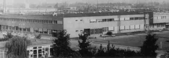
The new Halle 4 in Krefeld, especially for tuner and other modules manufacturing. Tuner development was on the first floor around two sides of the hall, and would remain there for the next 30 years. [Radiomuseum.org]
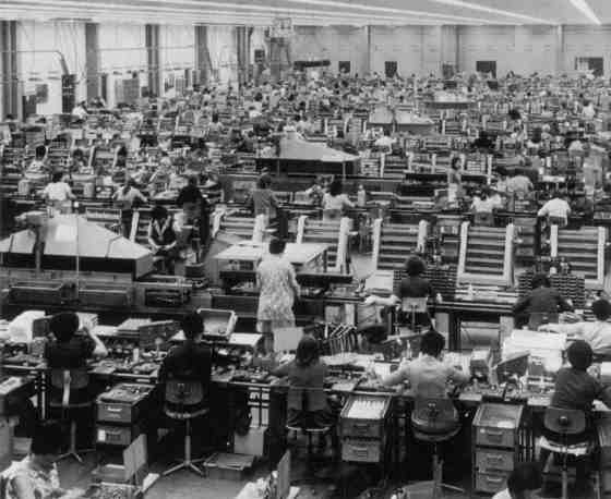
The interior of Krefeld Halle 4, completely filled with module assembly and alignment lines, including those for tuners. [Radiomuseum.org]
|
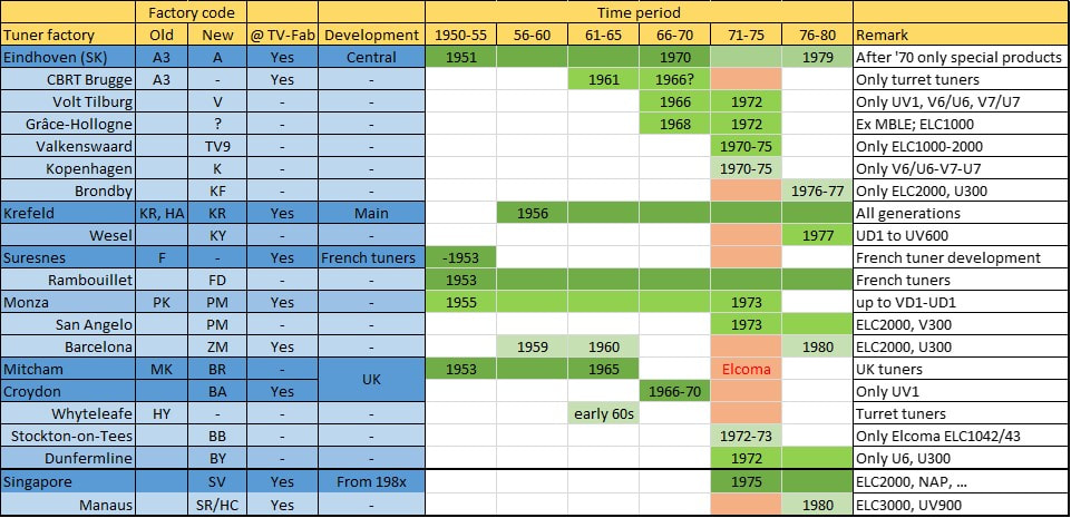
Overview of the (known!) Philips tuner manufacturing sites up to 1980. The darker the green colour, the more important the fab. The Elcoma period is also indicated. Especially on the smaller factories this data is mainly based on the production labels on tuners, where the factory codes indicate the tuner origin and time of production. See the columns "Factory code", where the new codes were mostly introduced together with the 12nc coding scheme.
Cable reception
This section has been substantially shortened compared to the original text.
The book also contains new sections on the early antenna amplifiers, cable amflifiers, and central antenna installations
To standardize cable transmissions a number of channels was defined by the CCIR, although they were strictly spoken no "radio" channels. These were coded S1-S41, with the S probably from German Sonderkanal (Special Channel). Channels S1-S10 were the Mid Band, between FM radio and VHF-III, channels S11-S20 the Super Band between VHF-III and the upper limit of VHF, while the Hyper Band (S21-S41) filled the UHF up to the edge of terrestrial channel E21 at 470MHz. Especially the Mid Band was a welcome bandwidth extension and initially widely used in the emerging cable networks that often didn't have a bandwidth much higher than 250MHz. However, as we will see, the first cable tuners of Philips, like the V415, covered immediately both the Mid and Super Band cable channels. Hyper Band tuners were only introduced towards the late 1980s (e.g. the UV616).
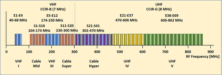
The Europaen CCIR TV channel allocation for both off-air (E1-E69) and cable (S1-S41) channels. Note that for all VHF channels (up to 300MHz) channel bandwidth is 7MHz, for UHF 8MHz, both for terrestrial and cable.
The V300-U300 family, 1975
|
After almost ten years of mysterious or at least less transparent tuners V6/U6-V7/U7-VD1/UD1-V311, the mist pulled up and the "real" V300-U300 family emerged. This is largely due to the data books that Philips Elcoma started to publish from 1968 onwards, which ended the period when often not more than the 12nc or service 12nc were known. The V314, U321 and U322, being the first members of the new generation, were introduced in 1978 together with the new K12 CTV chassis. The tuners were characterized by the following elements, some carried over from the previous generation, some newly introduced:
|
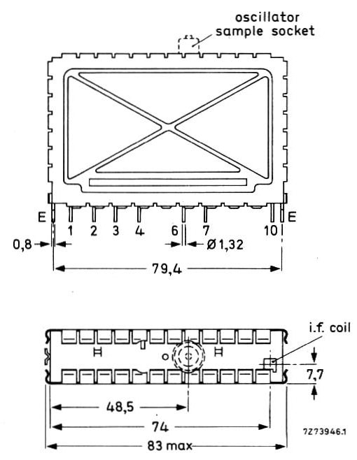
Mechanical drawing of the Philips V300-U300 tuner family. This is the U322 with the RF input on pin1 on the left. VHF tuners had the input on the right side.
Note the optional LO RF connector on the top. [Philips Elcoma Data Book CM3a, September 1978]
|
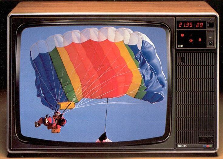
The new Philips K12 CTV chassis from 1978. This is the 26C790. It introduced the new V314 and U322 tuners, infrared remote control and storage of 29 channel pre-sets. [Philips product catalogue 1979]
|
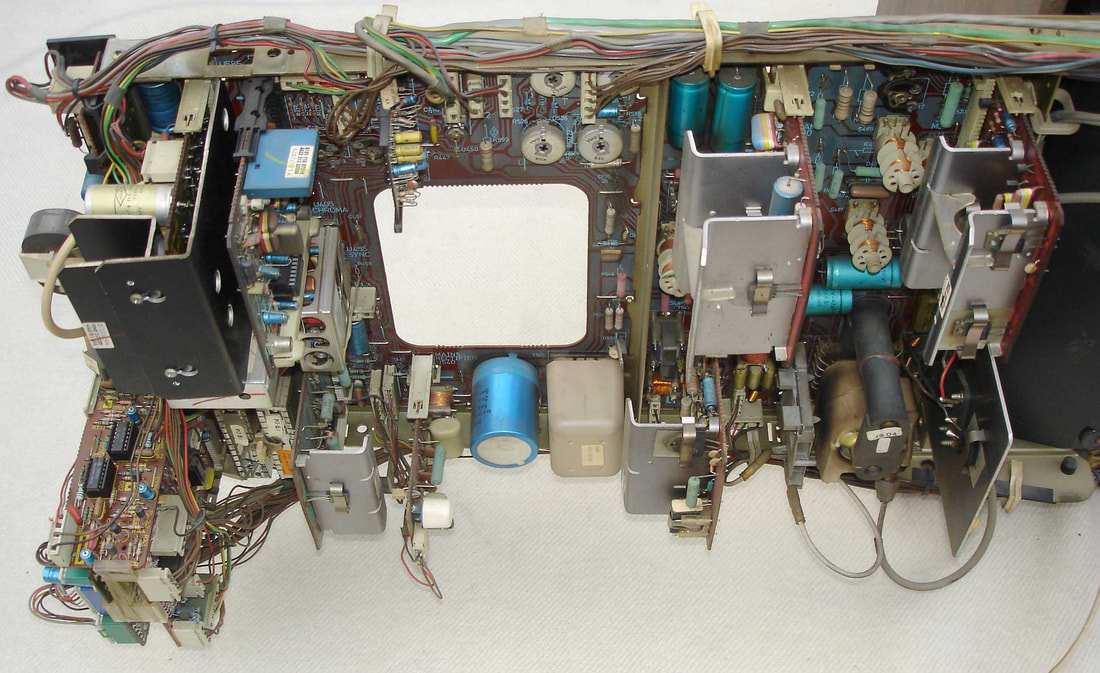
Front view of the Philips K12 26C790 TV set. Because of the increasing number of features the main board received quite a few plug-in sub boards. The two tuners became completely built-in and barely be seen lower left. [Marcels TV Museum]
|
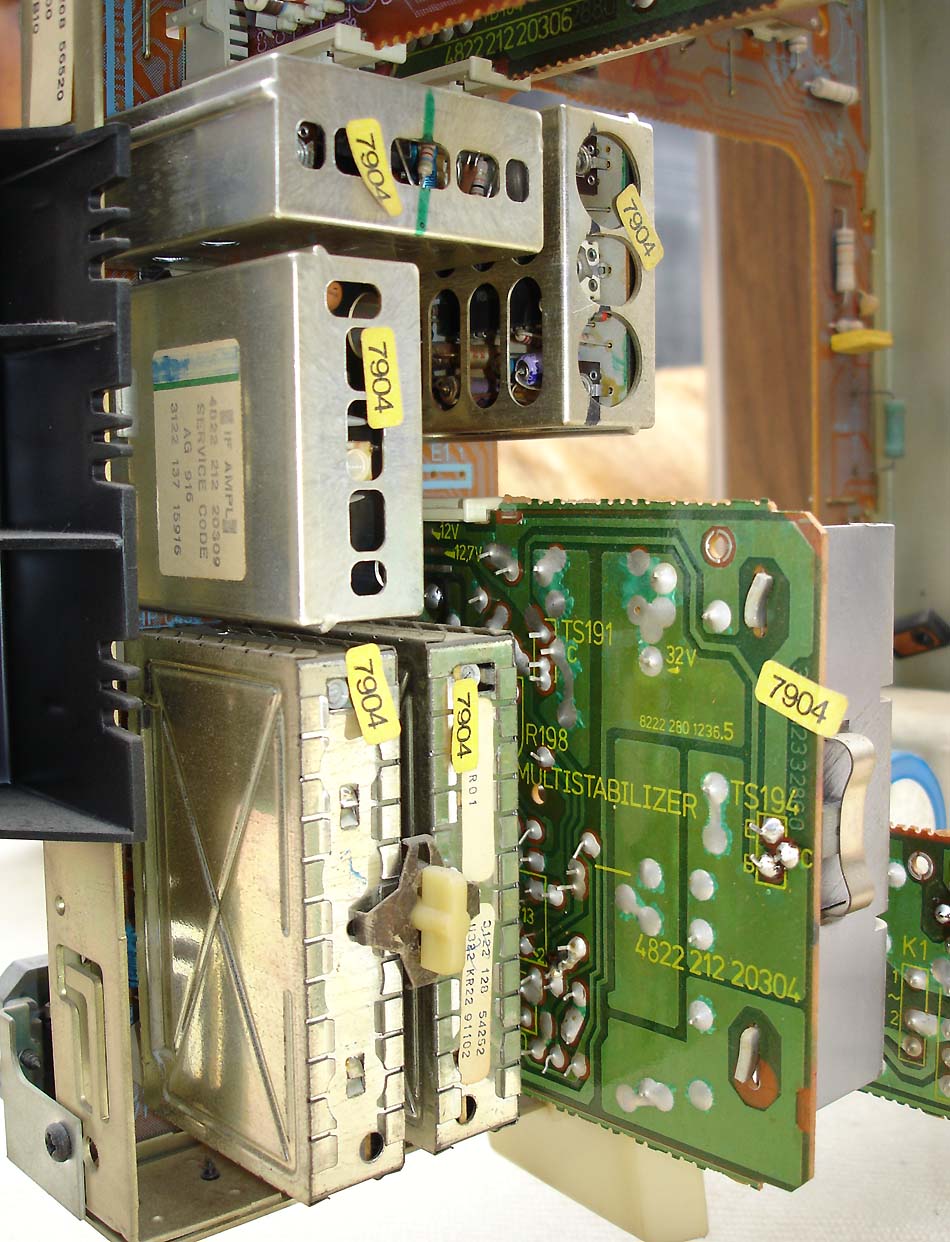
The V314 (right) and U322 (left), jointly fixed by the characteristic large plastic screw, in the KT2 chassis 20C841/50Z. [Marcels TV Museum]
|
The V314 successor of the V311 was a kind of intermediate step, and it could equally well be seen as part of the previous generation. Essentially it was a V311 with two modifications:
|
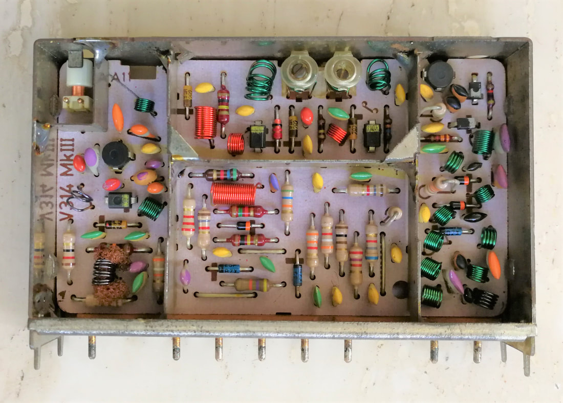
The Philips UV314, very similar to the V311 except for the simplified tuning voltage control in the central section. [Oswald Moonen collection]
|
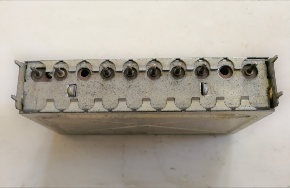
The pinning side of the V314, clearly showing the off-centre pin block mounting. Pins have become much thicker and are solidly fixed inside the PCB strip.
|
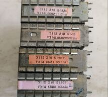
Coding labels of two Philips V314 and two V314LO samples. [Oswald Moonen collection]
|
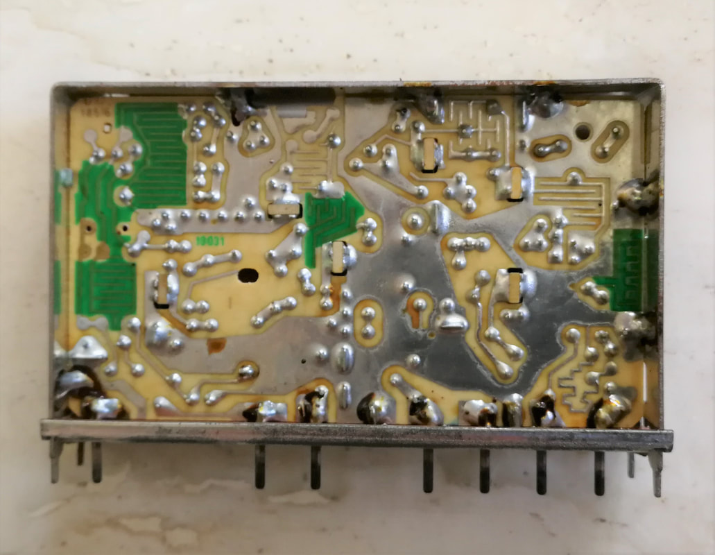
The back side of the Philips U322 UHF tuner. Note the use of inter-digital printed-board capacitors. [Oswald Moonen collection]
|
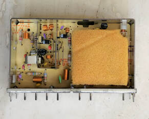
Early version of the U322. Probably for damping parasitic oscillations a piece of foam covers the oscillator section. On the left is the BF480 pre-amp transistor.
|
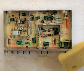
A later version of the U322, with now an ON611 as pre-amp transistor. In the centre just above the oscillator compartment with the orange marking is the BA280 mixer diode.
|
The first really new design of the second 300-series was the V315, based on an architecture that went back to the VD1 tuner of the previous generation. The main characteristics and innovations were:
- from now on all 300-family tuners would be based on silicon transistors. In this context it is interesting to note that these transistors became predominantly PNP again, like for the germanium transistors, whereas the first generations silicon bipolar transistors were all NPN. As explained earlier, this was probably on request of the tuner organization to maintain backward compatibility with the germanium transistor designs;
- it re-introduced tuned input matching filters;
- the UV315 used separate branches for VHF-I and VHF-III, that were switched right after the input filter (but before the pre-amplifiers) and after the BPF before connecting to the mixer. There remained a single oscillator with switched tank circuit inductors;
- the UV315 introduced cable channel coverage. To this end the two VHF bands were substantially extended compared to classical off-air tuners up to now:
VHF-I covered Channel E2 (PC 48,25MHz) to S1 (PC 105,25MHz)
VHF-III covered channel S2 (PC 112,25MHz) to S17 (PC 237,25MHz), which included off-air channels E5-E12 between 175,25 and 224,25MHz.
|
The V315 was introduced shortly after the V314, and both were used in parallel for at least 3 years, depending on whether the set required cable tuners of not.
In 1980 the V317 appeared, which introduced surge protection of the RF input, but was otherwise almost identical to the V315. The protection was made using a fast switching BA220 diode in reverse bias of a few Volt. In case a large RF voltage surge appears at the antenna (e.g. due to a lightning strike at the aerial) the diode switches on (in principle within 4ns) to connect the sensitive RF inputs to ground and protect the two pre-amplifier transistors. |
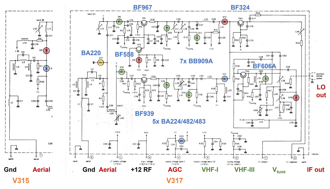
Circuit diagram of the Philips V317 VHF tuner (right) and the input circuit of the V315 (left) which is otherwise identical to the V317. Green diodes are varicaps, blue diodes switch VHF-I, red diodes VHF-III, while the yellow diode is the surge protection. [Philips Elcoma Data Book CM3a, 9-1978 and CM2, 12-1982]
|
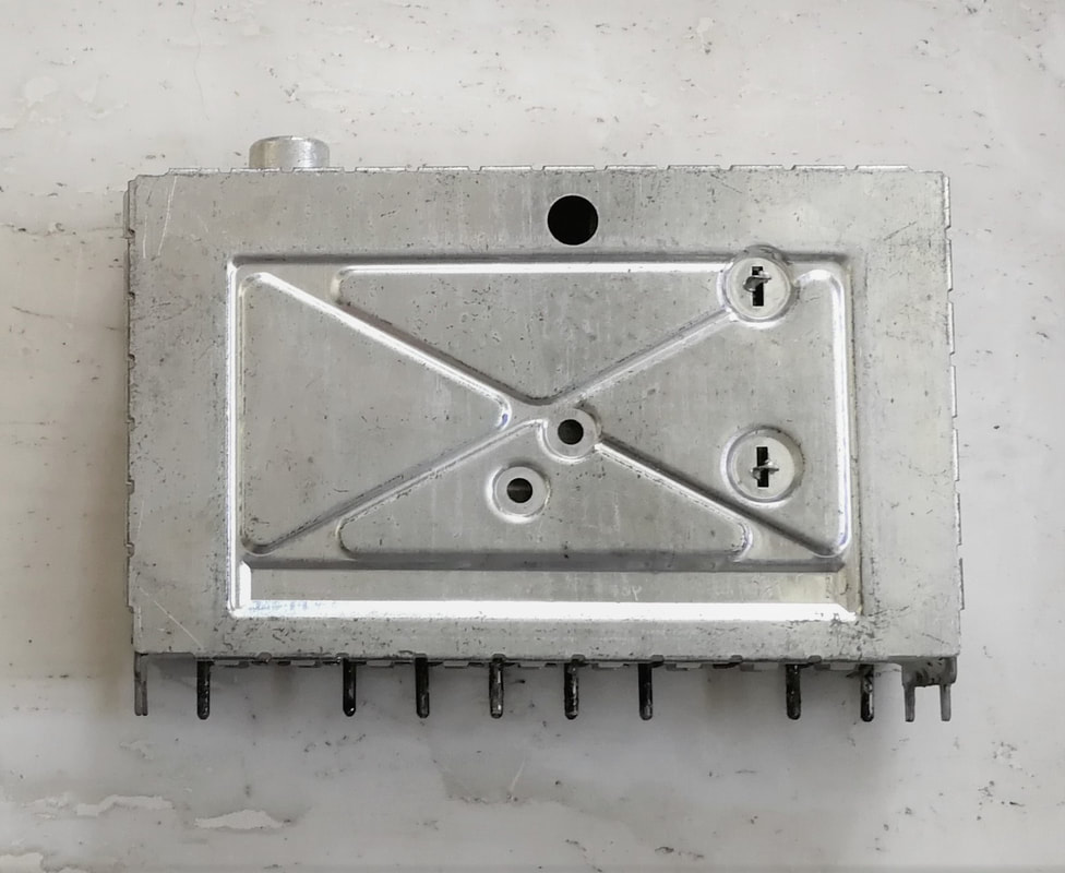
The Philips V315 introduced a cover modification, with on the front 2 extra holes for securing the cover with twisted pins. On the backside one hole was used to solder the cover. [Oswald Moonen collection]
|
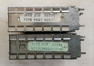
Coding labels of a V315 and V315LO, both Krefeld-produced. [Oswald Moonen]
|
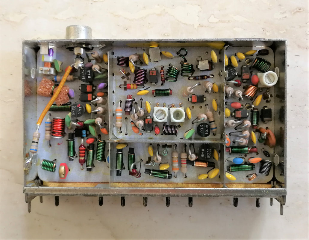
Linked to its new circuit concept the Philips V315 VHF tuner had a re-designed partitioning. Note the LO output, which picks up the signal through the lead of a long 68 Ohm resistor (covered by an orange socket).
|
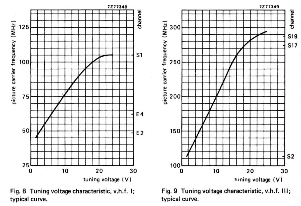
The tuing characteristics of the V315 tuner, showing the extended tuning ranges compared to the classical VHF-I and -III terrestrial-only tuners.
A typical label of a late 1970s Philips tuner, in this case the U322: 3122 128 54252 is the 12nc, U322 the type, KY22 the Wesel factory code, indicating two product upgrades since the KY20 introduction, and 829 the year (1978) and week (29) production date.
|
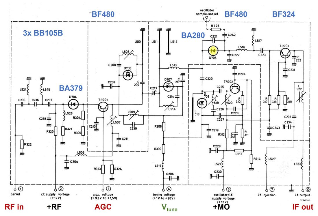
Circuit diagram of the Philips U322 UHF tuner. In yellow is the mixer diode. In later versions the pre-amp BF480 was replaced by the ON611, which was non-commercial Philips internal-only transistor type, likely a slightly improved BF480. [Philips Elcoma Data Book CM3a, September 1978]
|
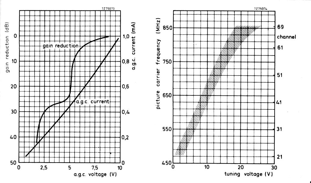
The U322 gain (AGC) and frequency (tuning) control characteristics.
|
The UHF counterparts of the V315 and V317 were the U321 and U322. The first one was the UK version, with the traditional current-driven AGC and the new RF input on the side, like the French VF5 and UF5 discussed earlier. The U322 was the standard European UHF tuner, based mostly on a traditional UHF varicap tuner concept. What was new in the U322, however, was the introduction of a mixer diode, the BA280 Schottky diode, skipping the self-oscillating mixer concept. The oscillator was built around a dedicated BF480 transistor, while the mixer diode with its obvious signal reduction (it had a specified Noise Figure of 8dB at 900MHz) was followed by a third transistor, the BF324 IF amplifier. Apparently the integral performance of a diode followed by an amplifier was better than that of a single self-oscillating mixer. Also note that the mixer diode was not forward biased, both sides were DC grounded.
|
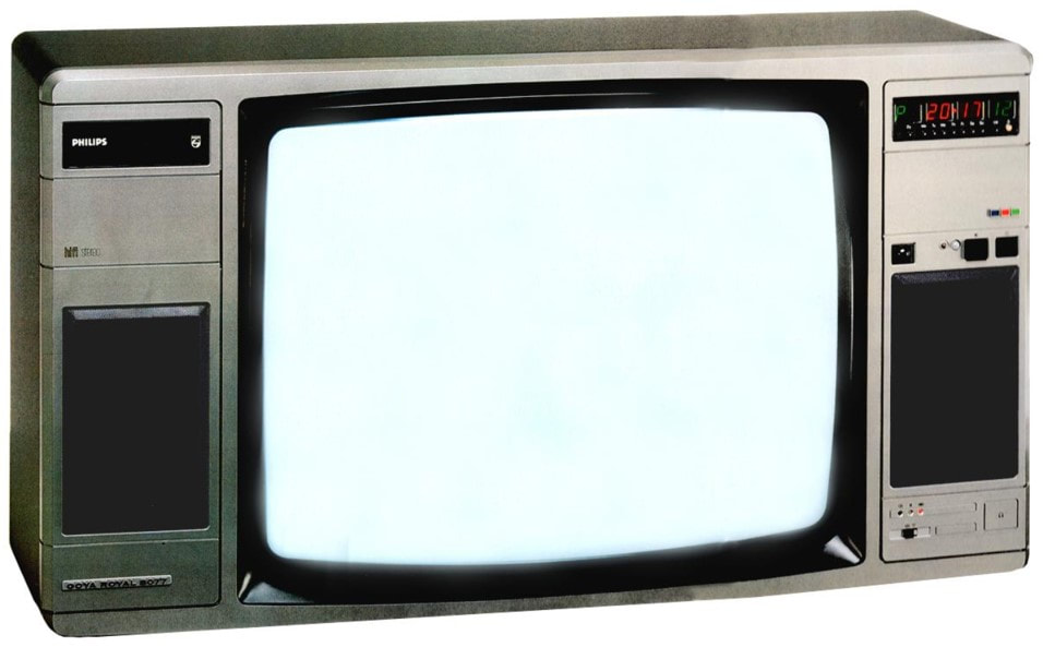
One of the last K12 versions, the K12Z from 1981. This is the 1982 model 26CP2501 Goya Royal Stereo 8077 with two full HiFi sound channels. It was one of the last models produced in the Krefeld fab before that converted to VCR production. [RadioMuseum.org]
|
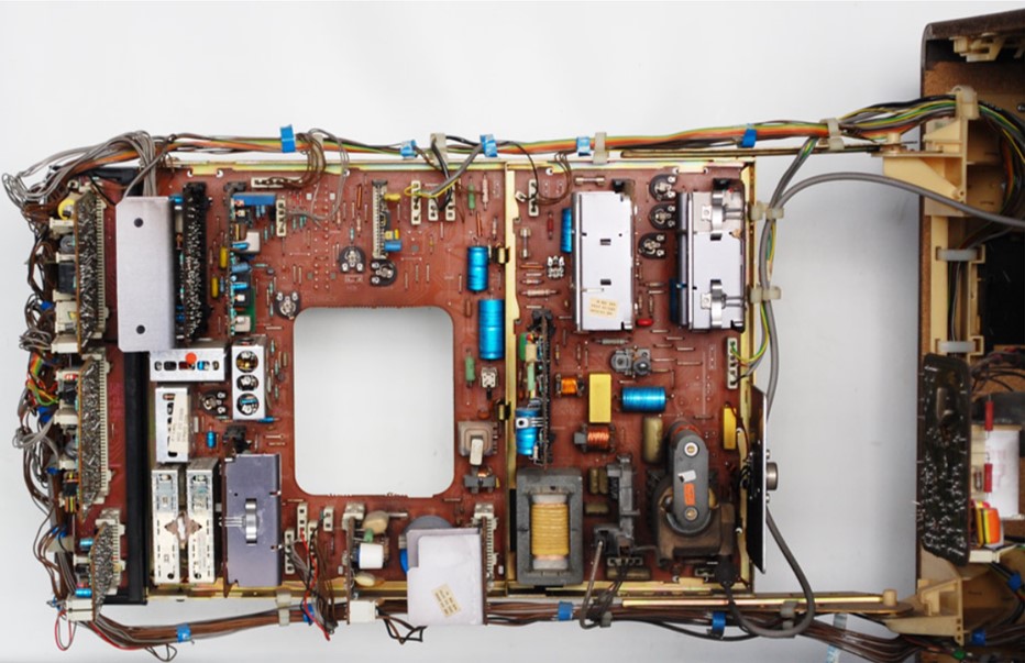
Nice view on the swung out main panel of the K12Z, in this case the 26CP2313 Goya Automatic 8065. Lower left the V315 and U322 tuners. [RadioMuseum.org]
|
The Philips K30 platform was the successor of the K12Z. Its main innovation was the introduction of Teletext, where the Teletext decoder was still a complete PCB full of ICs. This set is the Goya 8146. [RadioMuseum.org]
|
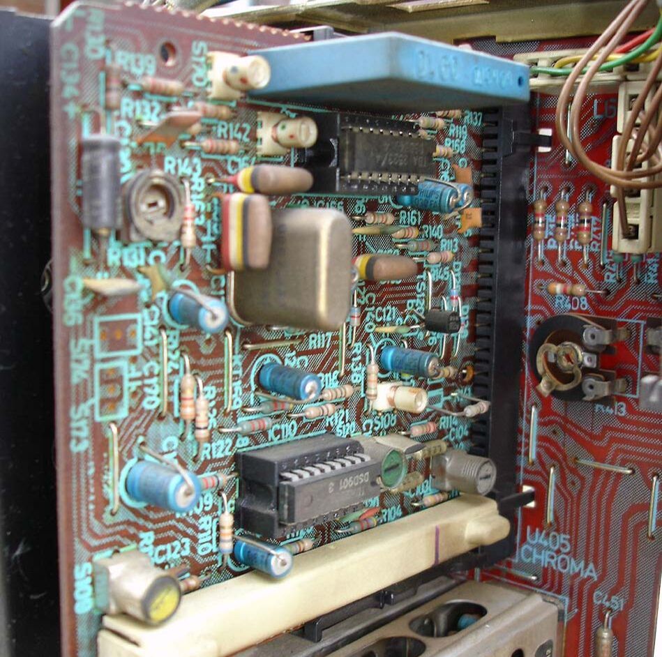
The K12 and K30 were the first platforms to use serious numbers of ICs, which were mostly placed on sub-boards. This is the chroma board of the K12, with the Philips TDA2523 and TDA2560. [Marcels TV Museum]
|
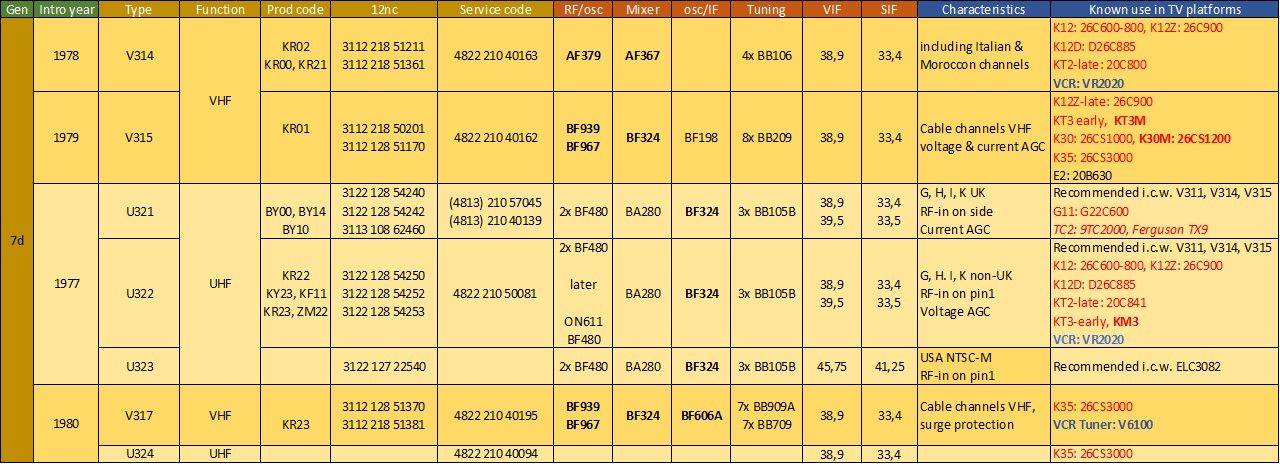
Overview of the V310-U320 Philips tuner family. For transistors bold= PNP, normal= NPN. From the last column it is clear these were the standard tuners in the K12 and its successor CTV chassis KT3, K30 and K35. Bold red = Belgian/French multi-norm.
300-LO tuners, TRD and the first FLL, 1977
|
In the course of the K12 platform life a number of innovations were introduced, based on the emerging digital processing ICs: infrared remote controls and microcontroller-based digital displays, automatic tuning and on-screen displays. Although there were multiple versions, the most advanced sub-system was usually referred to as Digital Channel Select (DiCS) system by Elcoma, or Tuning-Remote-Digital (TRD) by Video. It was introduced in the K12Z platform in 1981, which also introduced the isolated ("cold") chassis to allow the connection to Video Cassette Recorders (VCR) through SCART connectors. Although it goes too far to present the TRD system in all its aspects, I'll discuss the automatic tuning system around the tuner.
Part of the TRD system was the automatic scanning and channel storage loop, which required measurement of the actual tuner LO frequency. Therefore the LO-versions of the 300-series tuners were introduced: every member of the V300-U300 tuner family had a derived versions with a phono RF connector on the top of the frame, providing an output of the local oscillator signal. The V314LO, V315LO, V317LO and U322LO were most widely used, but there were more, including regional versions. The centre of the automatic tuning system was the Philips Elcoma SAB2024 integrated circuit (IC), a 24-pin DIL 1-micron MOS-IC with embedded EEPROM (Electrically Erasable Programmable Read-Only Memory) in which the standard LO frequencies of 100 channels were stored. The operation of the system is most easily explained using below circuit diagram. |
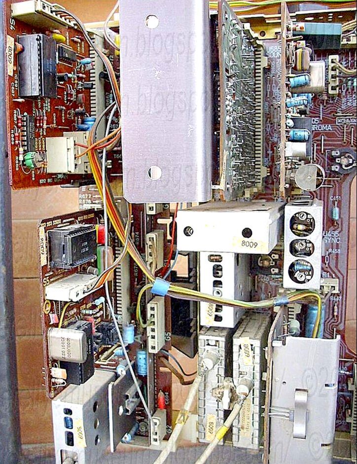
The V315LO and U322LO tuners with their top phono-connectors in a Philips K12Z set. Clearly visible are the two coaxial cables connecting the LO-signals to the TRD module (lower left corner). [Obsolete Telly]
|
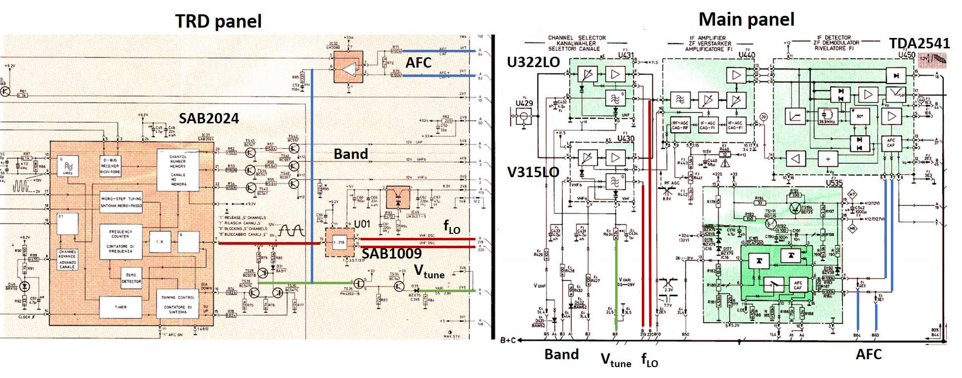
Circuit diagram of the TRD system in a Philips K12Z chassis. On the main panel (right) we see the V315LO and U322LO tuners, connected to the IF amplifier module U440 and from there the IF detector based on the TDA2541 IC, which includes the AFC frequency discriminator. The LO frequency samples from the tuner top contacts are connected (red lines) to an SAB1009 1/256 pre-scaler, that connects the LO/256 signal to the SAB2024. The balanced AFC signals are buffered by an LM3040 and added to the tuning signal coming out of the SAB2024 (green), which is connected back to the varicap voltages of the tuners. [Philips K12Z Service Manual and Philips Elcoma Data Book Part 6B, August 1979]
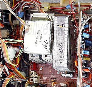
The TRD4 pre-scaler module PREM-4 directly mounted on top of the V334LO and U342LO tuners in the K35 chassis 26CS3270 from 1982. [Obsolete Telly]
|
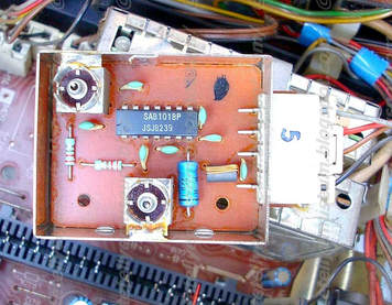
The SAB1018 1GHz 1/256 pre-scaler IC inside the PREM-4 module. The two phono connectors for the LO inputs from the two tuners are clearly visible. By mounting the PREM-4 directly on top of the tuners long RF cable could be eliminated. [Obsolete Telly]
|
|
In the SAB2024 the LO frequencies of each VHF and UHF channel are stored in the EEPROM, rounded to integer frequencies. (The SAB2034 did the same for Italian channel frequencies). When selecting a to-be-received channel, the frequency of the wanted channel is stored as a digital number in a 10-bit Frequency Up/Down Counter, which will start counting down with every pulse of the pre-scaled signal from the LO (256x frequency divided in the external pre-scaler, 8x inside the SAB2024). This is done during 2048us. If the actual LO-frequency of the tuner is lower than the wanted LO-frequency, the counter will not be at zero at the end of the 2048us period, and the UP output (pin 15) will give a pulse with a duration proportional to the remaining number in the counter. This pulse will charge an integrator (TS28-TS30) that drives the tuning voltage (green lines) up in voltage, driving the LO to a higher and roughly correct frequency. Similarly, when the LO frequency is higher than desired the counter will count to zero and then up again. A zero-crossing detector interprets this as a higher frequency, driving the DOWN pulse instead (pin 16) and forcing the integrator and tuning voltage to lower voltages. When the difference between wanted and measured frequency has become less than roughly 0,5MHz the digitally controlled tuning will stop, the pin AFCON (pin 11) goes high, and the AFC loop (blue lines) will be closed and take over.
The SAB2024 could be set to include CATV (S-channels) through pin 2, see also the table on the right. The channel frequencies were also driving three separate outputs for the band selection (pin 20-22 for UHF, VHFb, VHFa). 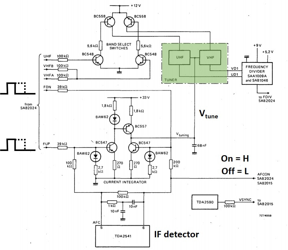
Reference design of the FLL circuits between the tuners and the SAB2024. [Philips Elcoma SAB2024 Data Sheet]
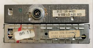
Top view of a U322 (bottom) and U322LO (top). Note that in the UHF tuners the LO phono connector was more to the centre of the tuner than the VHF phono. The first is Krefeld produced in 1977, the LO-version in Eindhoven in 1978. [Collection Oswald Moonen]
|
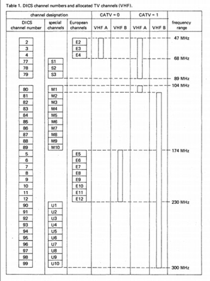
Overview of the VHF channels as stored in the SAB2024 memory. Depending on the bit line CATV the S-channels (here coded M and U) were included. [Philips Elcoma SAB2024 Data Sheet]
The last feature of the SAB2024 that needs mentioning is the search tuning. In this mode the IC is put in micro-tuning mode, with frequency steps equal to 1/7th of the channel width. In this way it will step through a frequency band.
It is interesting to note that the reference application of the IC and the one used in the chassis are not identical. On the left the first, which is a nice addition for understanding the basic operation. The main differences in the K12Z implementation are the buffering of the AFC control signals, as well as the Vtune output, using a MOSFET. The successor of the SAB2024 was the SAB3024, which no longer had the programs stored internally but received them from the micro-controller, used a twice longer counting window (4096us) and offered a much smaller frequency inaccuracy of only 96kHz, allowing AFC-less systems. The SAB3024 was introduced as the TRD4 system in the K35 chassis, together with the SAB1018 pre-scaler, that was now in a small module mounted directly on top of the two LO-tuners. |
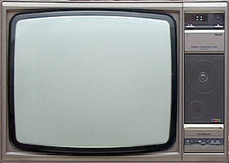
The K35 was a very advanced platform, with a few new features based on digital technologies: teletext (introduced in the K30), a thermal printer for Teletext data, and the TRD control system. This is the 26CS3890. [Marcels TV Museum]
|
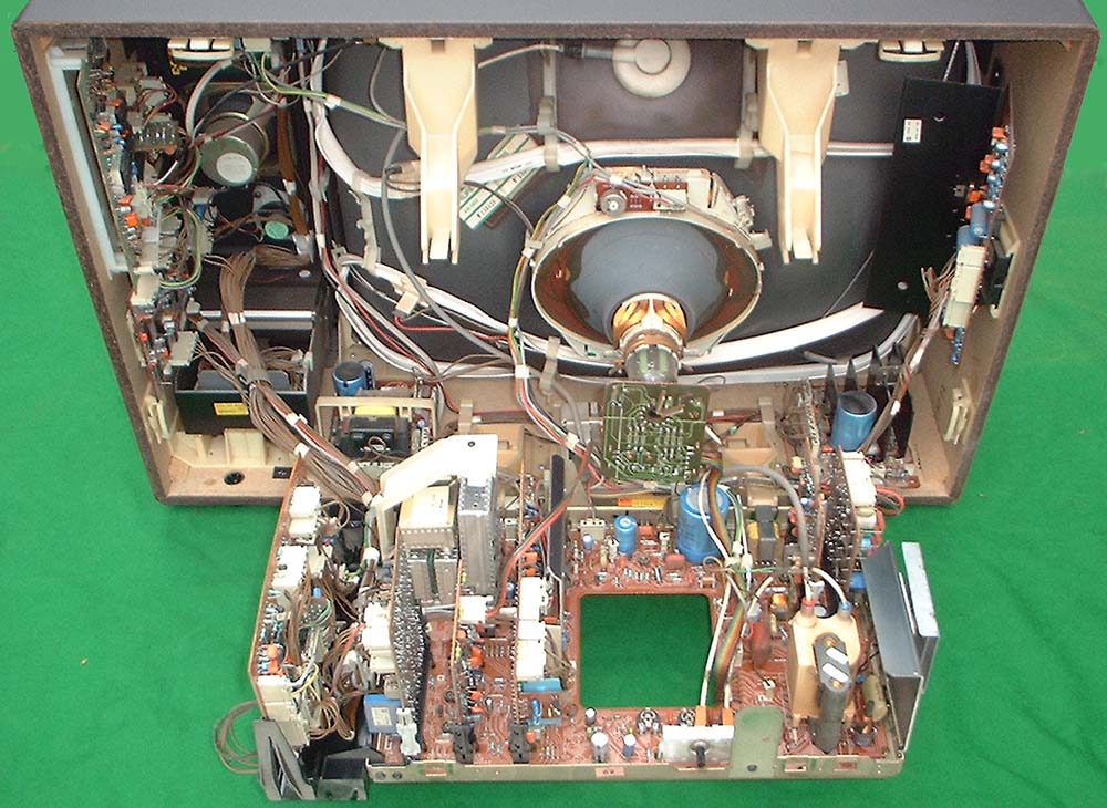
Interior view of the Philips 26CS3890. The V300LO and U300LO tuners with the prescaler can on top are visible next to the big IF can on the main board. On the left interior wall is the Teletext board, below left the thermal printer. [Marcels TV Museum]
|
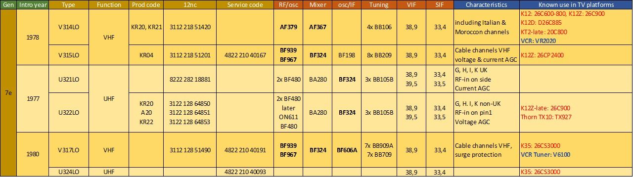
Overview of the Philips V310-U320 tuners with LO output for the TRD system.
The last 300-tuners, introducing the MOSFET, 1980
|
At the end of the family life time of the V300/U300 one more innovation was introduced: the MOSFET (Metal-Oxide-Semiconductor Field Effect Transistor). With the MOSFET replacing the bipolar transistor the equivalent (not the real!) circuit resembled the good old triode again, with very high input resistance (and thus effectively only an input capacitor) and a Vg-Ids characteristic that has the same form as a triode. But more importantly, with the dual-gate MOSFET concept the feedback capacitor from drain to input gate became very small, in the order of 50fF, an order smaller than in the bipolar transistor of the period. This effectively led to a serious input Noise Figure reduction: the NF improvement in UHF from the U322 to the U342 was 1dB at channel E21 (470MHz, from 7 to 6dB) and 1,5dB at E69 (860MHz, from 8 to 6,5dB). A considerable improvement! The second improvement associated with the MOSFET was the gain control, which was directly performed through the bias voltage of gate-2. Due to the enhancement mode construction of the device at Vg1-s=0V the drain current is already maximal at 10mA, where the source is typically biased at 5V. By driving Vg2 down from 9,2 (so nominally 4V above the source)to 1V (or Vg2-S=-4V) a minimal gain reduction of 30dB is achievable.
The MOSFET proved to be a major improvement, which was no surprise because it was used for almost ten years already in US tuners, with Texas Instruments and Motorola as main suppliers. In Europe Siemens was also several years ahead of Elcoma, and Philips was thus definitely not a leading player in the use of MOSFETs. But once introduced the MOSFET would remain the standard RF pre-amplifier in Philips tuners for the next 30 years, only to be replaced by the fully integrated silicon tuner! 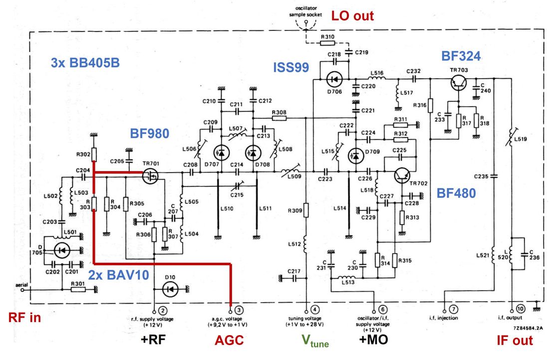
Schematic diagram of the Philips U341 and U342 tuners, introducing the MOSFET pre-amplifier. In red the AGC control connection to the MOSFET Gate2. [Philips Elcoma Data Book CM2, December 1982]
|
MOSFET principles
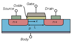
In contrast to the bipolar transistor, see earlier in this chapter, the emitter-to-collector current (here source-to-drain current) does not flow through the base control electrode. Instead the current flows through a channel between source and drain, which is modulated by the gate electrode overhead this channel. By making the gate-to-source voltage lower the channel width will be reduced until it is pinched off.
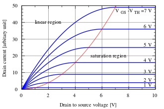
In dual gate MOSFETs the channel is effectively split in two, each section modulated with a separate control gate, making it a tetrode device. Gate 1 is used as RF input, and is shielded from the Drain by Gate 2, which is only used for DC gain control voltages. This substantially reduces the Miller drain-gate1 feedback capacitance, giving higher gain and lower Noise Figure.
|
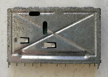
The U342 introduced the MOSFET pre-amplifier and at the same time also a new cover, with additional spring contacts for grounding. [Ite Weide]
|
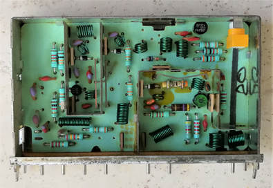
Interior view of the U342 with centre-left the BF980 MOSFET. Note the 4 pins. Bottom right the oscillator around the BF480, top-right the BF324 IF amplifier. [Ite Weide]
|
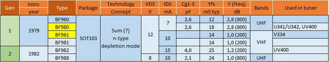
Overview of the first generations Philips RF MOSFETs used in the tuners.
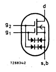
|
The first MOSFET used, in the V334 VHF tuner, was the BF961, a 200MHz device. The BF980, an 800MHz device, was introduced in the U411 and U412 the same year. Both were n-channel MOSFETs with gate protection diodes, to avoid the sensitive gates being damaged by voltage surges. For further surge protection both the antenna input as well as the +12V pre-amplifier supply pin received a BAV10 surge protection diode. There is one more interesting aspects of these two transistors, which both seem to have been type numbers only used by Philips internally, since neither the BF861 nor the BF860 can be found in the public data books. To further enhance the confusion, the public version of the VHF transistor BF961 is most likely the BF981, and similarly for the UHF BF980 the BF960.
|
In 1984 the last versions of the 300-family were released: the UHF-only U343 and U344. These were adapted for directly driving a Surface Acoustic Wave (SAW) IF filter. To this end the tuner included a full dual-tuned IF filter as well as an additional IF amplifier to compensate for the SAW losses. And secondly the U344 was the first and last 300-tuner to introduce a pre-scaler IC. The same was done with the UVF10 French tuner. Both these innovations were in principle rolled out as part of the next generation UV400 family, but for several reasons the UK and French organisations preferred to stay with the 300 tuner longer.
The 300-family of tuners had a long life, albeit with a number of technology upgrades. If we take the pin-compatible VD1/UD1 as the starting point of the 300-family, it lasted from 1972 to 1984. The platform supported the introduction of MOSFET pre-amplifiers as well as the electronic TRD tuning system, and as such was a major element in the very successful roll-out of the K12 and K35 CTV platforms that gave Philips a leading position in the CTV market.
The 300-family of tuners had a long life, albeit with a number of technology upgrades. If we take the pin-compatible VD1/UD1 as the starting point of the 300-family, it lasted from 1972 to 1984. The platform supported the introduction of MOSFET pre-amplifiers as well as the electronic TRD tuning system, and as such was a major element in the very successful roll-out of the K12 and K35 CTV platforms that gave Philips a leading position in the CTV market.
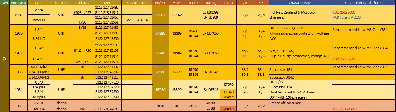
The last version of the Philips 300 tuner family, the V330 and U340 which introduced the MOSFET variable gain amplifier. For the other transistors it is still bold= PNP, normal= NPN.
ELC2000 Tuners, 1972
As explained earlier, after a brief period from 1970 to 1973, the independent Elcoma and RGT/Video tuner developments were integrated into a single tuner development organization on the Strijp complex (building SK3). When the Elcoma team, lead by Heinrich Bender, arrived there it probably had already started the development of its second generation tuner, the ELC2000. After the modest and probably disappointingly low success of the ELC1000 this next tuner was more traditional: no longer modular and a single folded metal frame. Most importantly, the ELC2000 family was the first to introduce the compact, integrated combined VHF-UHF tuner, albeit still based on separate tuners per domain. The main characteristics were:
- A single folded tin can box, with RF inputs at the opposite short sides of the can. There were still separate RF inputs for VHF and UHF.
- Internally a single PCB, although the VHF and UHF were galvanically separated by a heavily grounded screen. Only two lines were needed for interconnecting these two sections: the common Vtune line and the connection of the UHF mixer output to the VHF mixer, acting as IF amplifier. The PCB was made from polyester-glass, which had much better hygroscopic characteristics than the brown pressed paper PCB's used in RGT, which gave a lot of quality problems in the field, especially in humid areas.
- Compared to the combined V300 and U300 the ELC2000 was longer (110 vs 80mm) and higher (65 vs 52mm) but thinner (26 vs. 2x18=36mm), giving an integrally 10% smaller footprint.
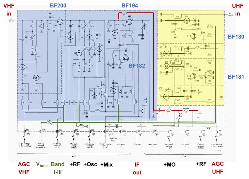
Circuit diagram of the Philips ELC2000S VHF-UHF tuner. Blue is the VHF section, yellow UHF. Both sections are of classical design: a switched VHF and a 2-transistor UHF tuner. The two inter-connecting lines are highlighted: red the UHF IF, green Vtune. [Philips Elcoma Data Book CM3 February 1972]
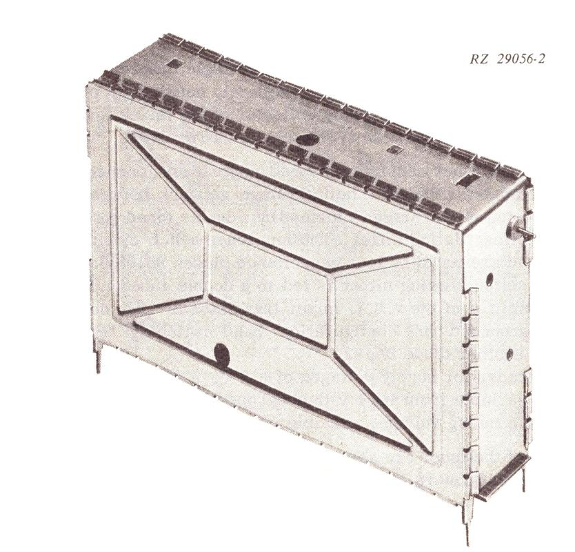
The Philips ELC2000S tuner.
|
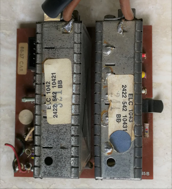
A set of ELC1042 VHF and ELC1043 UHF tuners as used in UK sets. BB on the labels indicates production in Stockton-on-Tees. [Ite Weide collection]
|
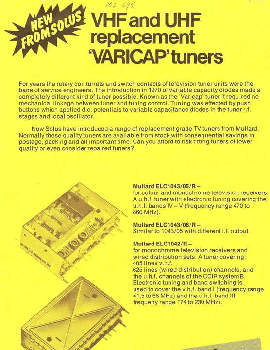
An advertisement from around 1970, pushing the ELC1043 UHF tuner as replacement of other tuners in UK sets. The picture shows the ELC1043. [UK Vintage Radio Forum]
|
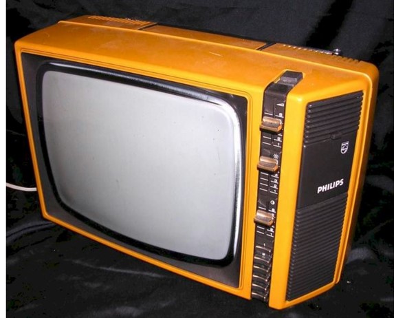
The first internal Philips chassis that used the ELC2000 tuner was the TS7 from 1975. This is the 12B312, a typical small screen set produced in Singapore. [RadioMuseum.org]
|
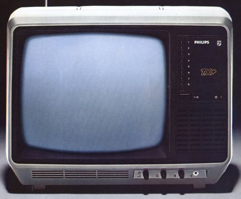
The last Black&White TV chassis to use the ELC2000, the TX from 1982/83. This was a very efficient all-transistor TV with one single sound IC. Later this chassis switched to the ELC2004. [RadioMuseum.org]
|
The ELC2000 was used as standard tuner for B&W TVs from 1975, first in the TS7, then the T8 and TX and finally the colour CTX, which were mostly smaller screen size (12, 14 and 20") portable TV's. The ELC tuners had made it to volume! In parallel a UHF-only version was introduced for the UK market, where VHF was being phased out and only used for the legacy 441-line system, while 625-line transmissions were only at UHF. This was the ELC1043, which was identical to the UHF section of the ELC2000 but with internal pot-meters for individual setting of the varicap tuning voltages.
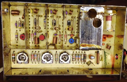
Top inside view of the Philips ELC1043 UHF-only tuner. At the bottom the three potmeters for varicap pre-setting. [VRAT2.0 Forum]
|
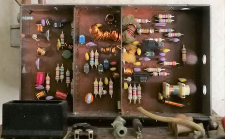
Top inside view of the Philips ELC1042 VHF-only tuner. [Ite Weide]
|
|
One of the cost reduction measures applied in the ELC family was undoubtedly the cheap frame. Especially the above two pictures show how thin it was, and that the screens were hand-soldered to the outer frame. Also the PCB-to-frame solder connections were critical, and proved to be a reliability issue over time. The oscillator apparently required an additional shielding cover, probably to compensate for the leaky frame as far as radiation was concerned. Another interesting technology indication we get from these inside views is the way the tuned circuits were aligned. In the UHF tuner the inductors are U-shaped pieces of metal, soldered on the PCB on both ends more or less overhead the tuning varicap. For alignment the two inductors could be bent towards or away from each other for the correct curves.
Soldering required some special measures, to avoid the wired components were pushed upwards by the soldering wave. So once all components were inserted, a special foam cushion, with holes to accommodate the larger components, was pushed onto the PCB while soldering. Because of the heat of the solder bath these foam cushions quickly turned black and were thus called "broodjes" (loafs of bread). They required regular replacement. After the initial success of the ELC2000 and its 1042 and 1043 derivatives, an upgraded model appeared with the ELC2004. Compared to the ELC2000 the 2004 offered Noise Figure improvement, especially in UHF (from 9,5 to 7dB typical at E21), although the key components remained the same. So the NF improvement most likely came purely from improved input stages, with better noise impedance matching to the pre-amplifier. |
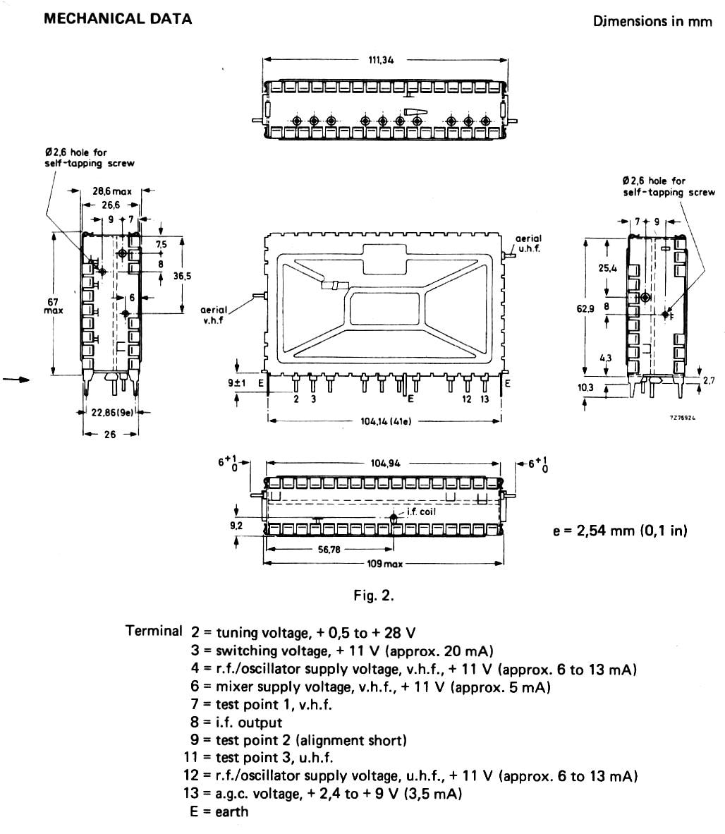
Mechanical drawing of the Philips ELC2004 tuner. [Philips Elcoma Data Book CM3a, September 1978]
|
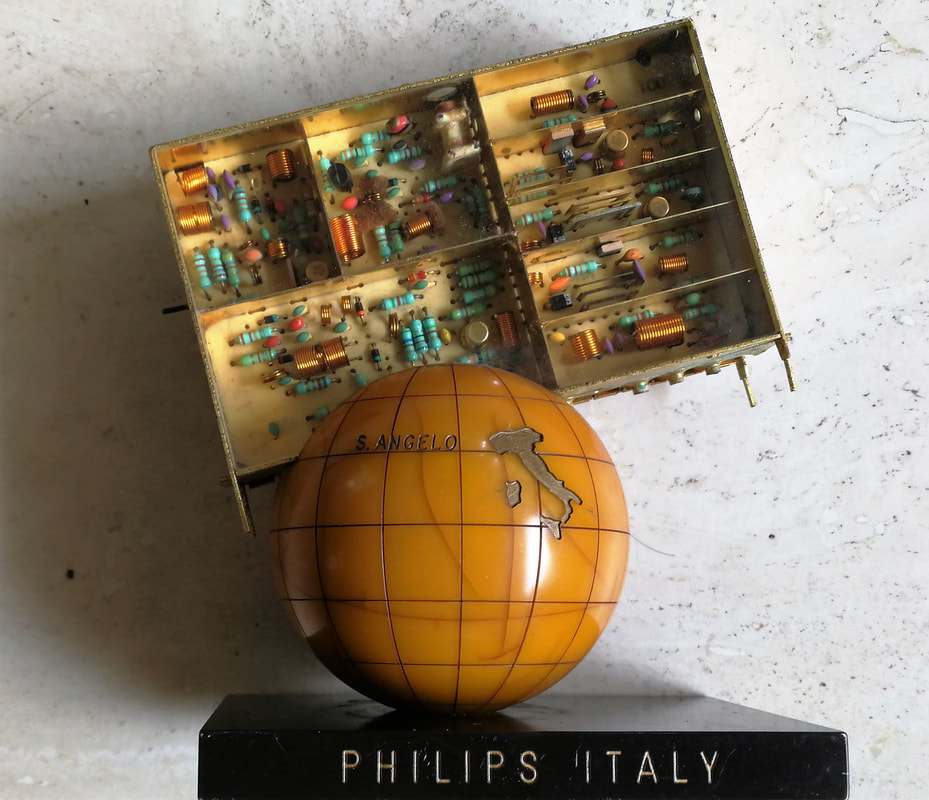
The ELC2000 was produced in large numbers for a long time, and thus the occasional trigger for celebrations. Here a trophy from the Italian San Angelo fab, which had produced its 10Millionth tuner. Around the socket it says on the four sides: Philips Italy - 1980 - 10.000.000th - tuner. [Johan Bos collection]
|
Initially the ELC tuners were mainly sold to external customers, also because the Philips Video organization was openly hostile towards the Elcoma tuners, although now part of their organization. Video bluntly refused even considering their use, especially in the higher-end Colour-TV chassis. The ELC tuners were therefore targeted at the external market, where most players were not focussing on high-end, on the contrary, and Elcoma had optimised its tuners for low cost. So whether Video liked it or not, the V300/U300 combination was too expensive for cheaper black and white chassis, and the ELC2000 obviously cheaper. The ELC2000 was thus quickly adopted in the main low end Philips chassis: the Singapore-built TS7, the Krefeld E2 and the Eindhoven T8 and TX. A real breakthrough, and triumph for the Elcoma tuners, was their selection for the flagship N1500 Video Cassette Recorder (VCR). This probably broke the resistance of the Video organization, and made the ELC2004 the ultimate success of this family: after a brief first phase replacing the ELC2000 in B&W chassis it quickly also started to replace the V314/315/317-U322/324 separate tuners in the high-end CTV chassis: the K30 (110degree picture tubes, 22 and 26" high end sets), KT3 (the 90degree tubes, 16-20" mid range TVs), the K30M (Belgian multi-norm sets) and the K35 (2nd generation of the platform). Apparently the advantages of a single integrated VHF-UHF tuner finally outweighed the slightly lower performance due to the cheaper construction. The ELC2004 lived for at least 7 years, an eternity for tuners in that period, and thus became the bridge from separate VHF and UHF transistor-only tuners to the next generation integrated UV400 modules that also introduced the first ICs.
|
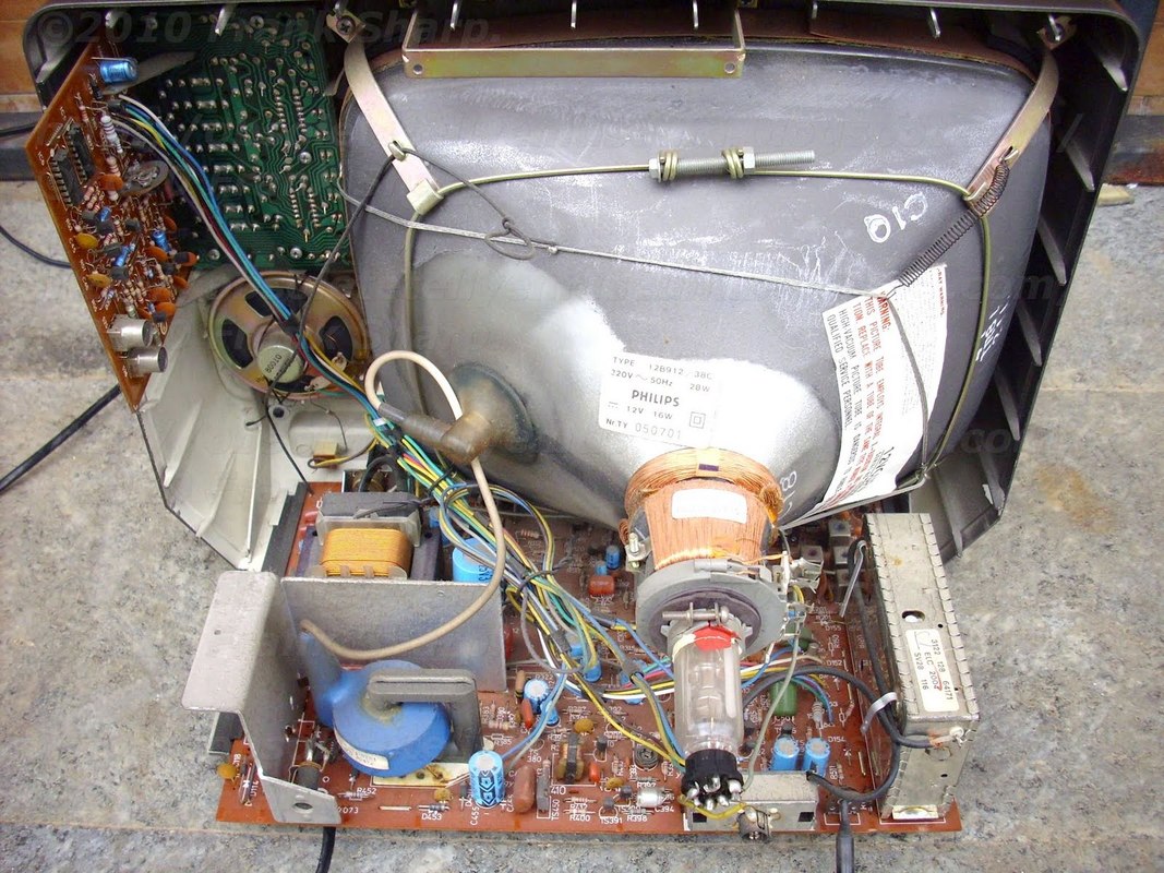

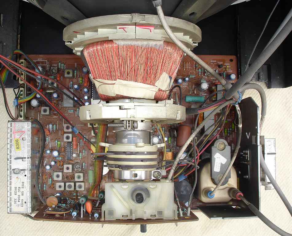
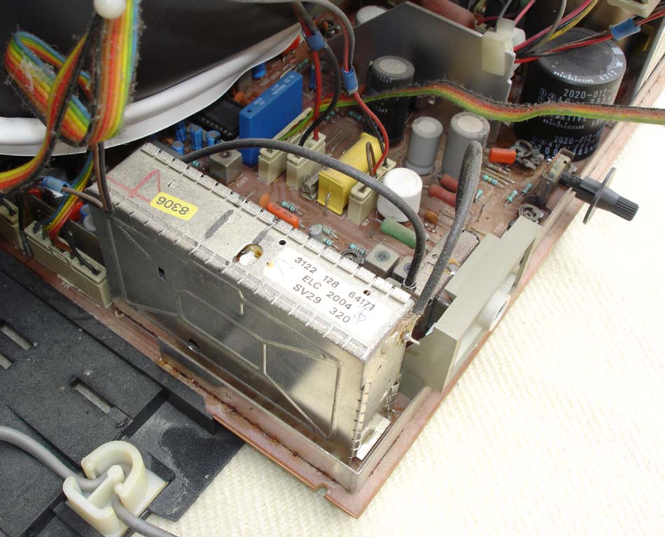
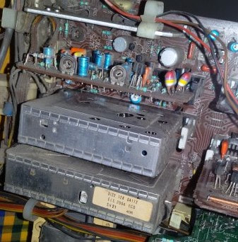
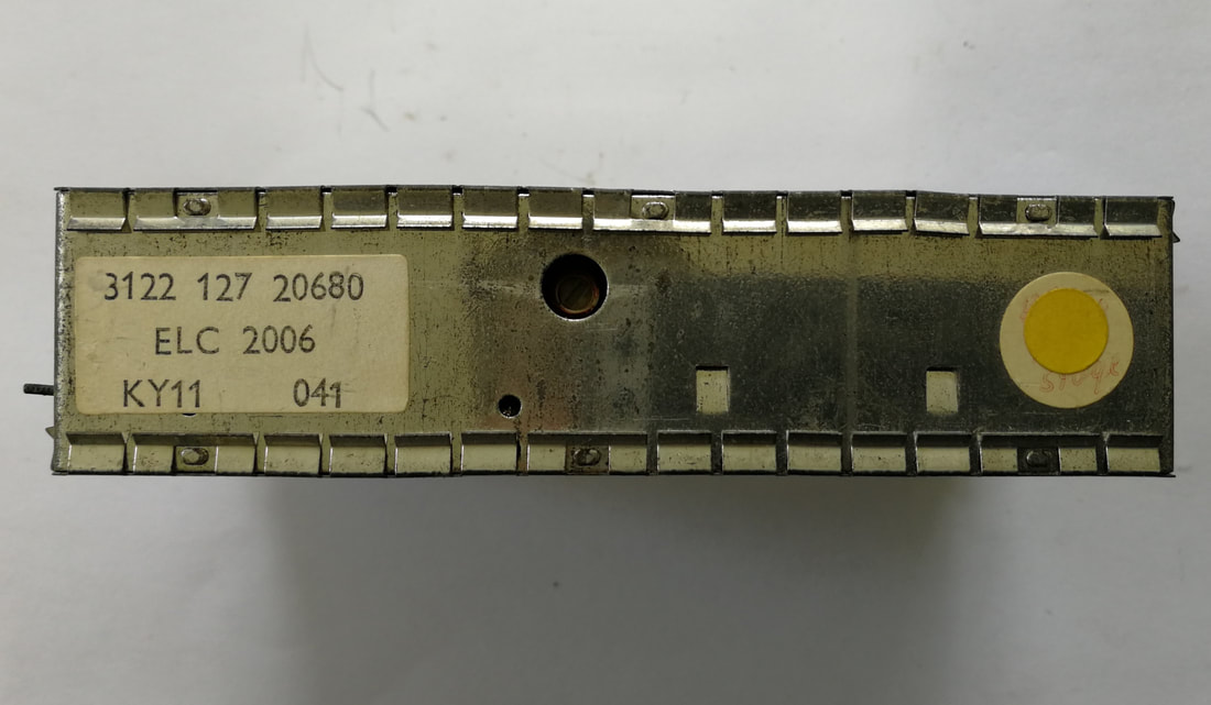
The later models of the ELC2000 family were widely used in Philips TV chassis. Here some examples. Top row left to right: ELC2004 in the TX-chassis 12B912 television. [Obsolete Telly]; ELC2004's were built in at least 4 different factories: Singapore (SV), Brondby (KF), Barcelona (ZM) and Wesel (KY). This one is from Barcelona, 1980, on a typical IF panel; The ELC2004 in the 1983 small screen CTX-platform 21CT2016. [Marcel's TV Museum]. Second row: Close up of the CTX set. After the picture tube the tuner and LOPT are clearly the largest and most expensive modules. This an SV29 model from 1983. [Marcels TV Museum]; The ELC2004 in the KT3 mid end CTV 20CT3322. Next to it is the shielded IF module. [UK Vintage RR Forum]; An ELC2006. The fixing hooks for the covers are clearly visible. KY indicates production in Wesel, Germany. [Oswald Moonen collection]
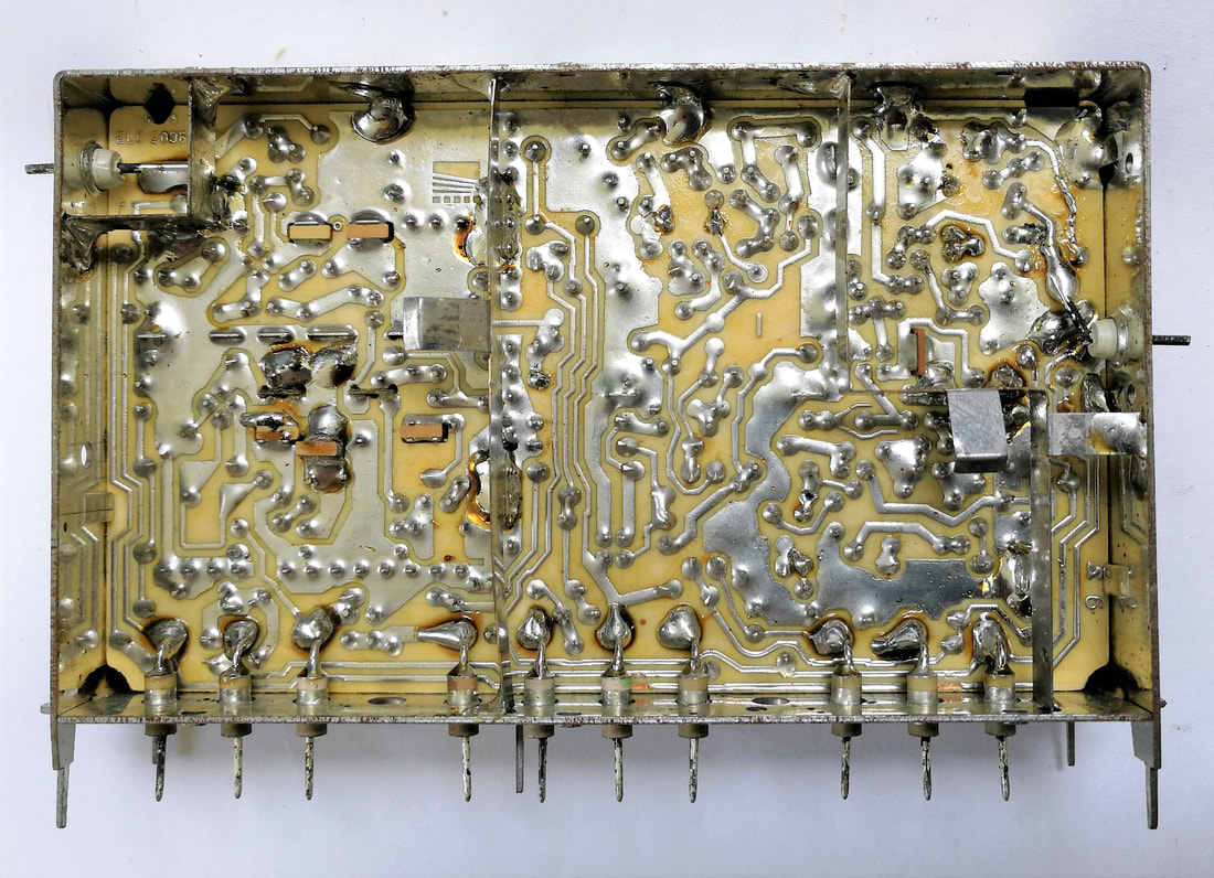
The back side of the Philips ELC2006. The two RF inputs (left UHF, right VHF) are clearly visible. Some metal shields are used for grounding bridges. [Oswald Monnen collection]
|
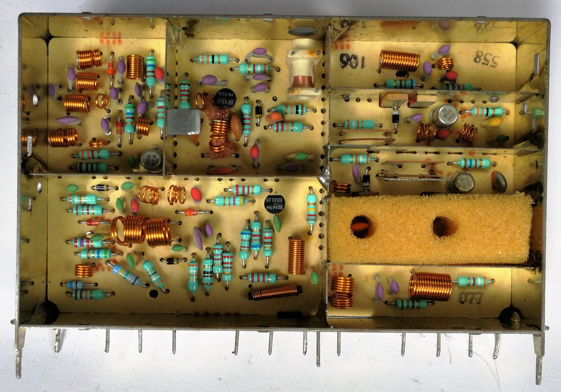
Top side interior view of the ELC2006, which was very similar to the ELC2004. Now on the right side the UHF section, on the left VHF.
|
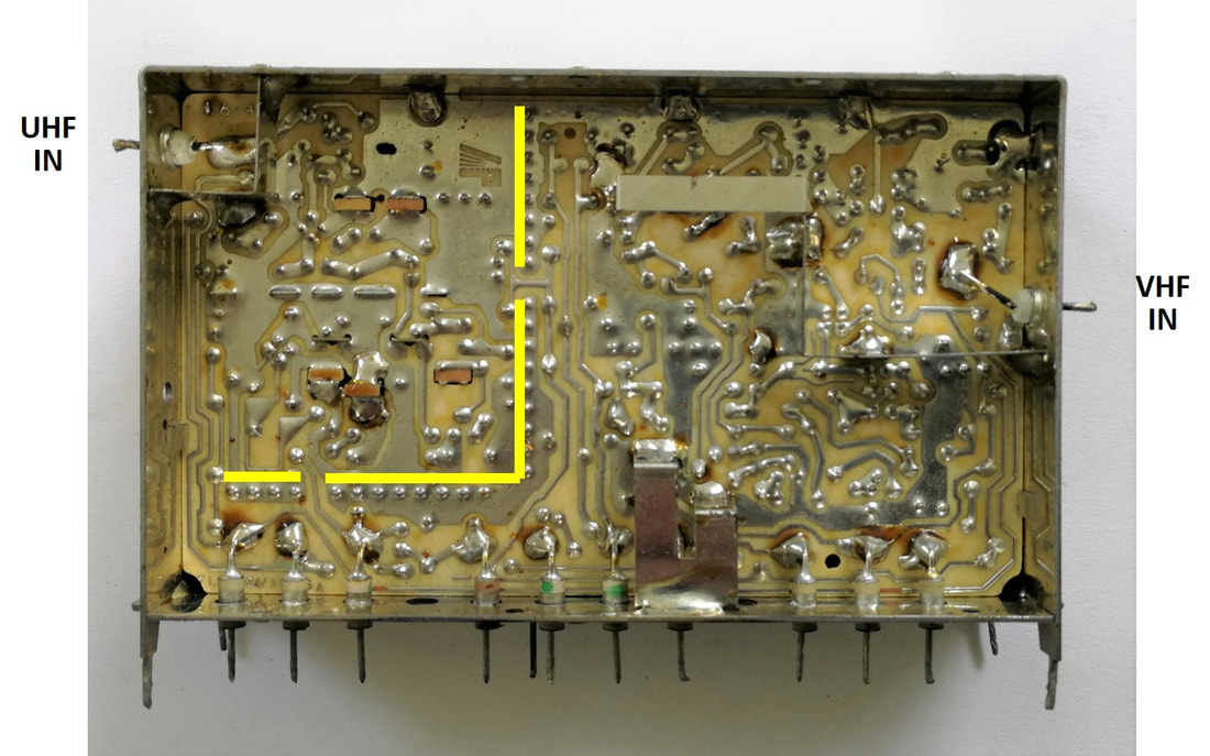
Back side view of the Philips ELC2004. In yellow the long row of solder points of the UHF screen, isolating the UHF section from the VHF. There are only two small signal passing openings. [Collection Oswald Moonen]
|
Starting from the ELC2004 again multiple derivatives were designed: the ELC2003 UHF-only as successor of the ELC1043, the ELC2006 covering S-channels S2-S19 and the ELC2060 and 2070 for Australia and South Africa, respectively. The final family member was the ELC3082, a VHF-only tuner for the US market, introducing a 4th BF324 transistor as IF amplifier, most likely for extra drive power of the newly introduced SAW IF filters.
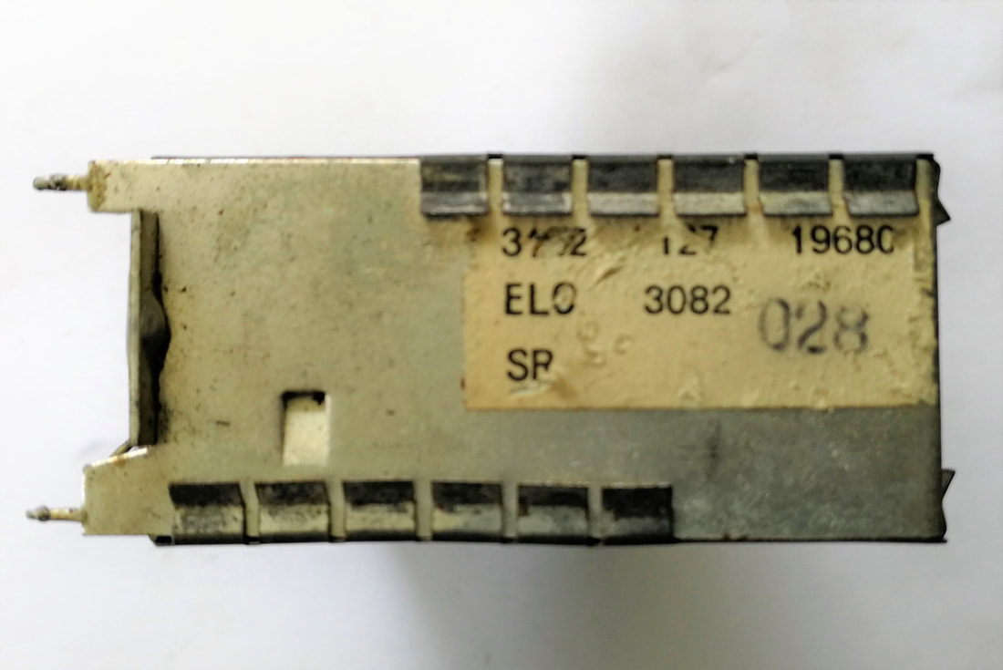
A rare Philips ELC3082 NTSC tuner, produced in Manaus (factory code SR), Brasil. [Oswald Moonen collection]
|
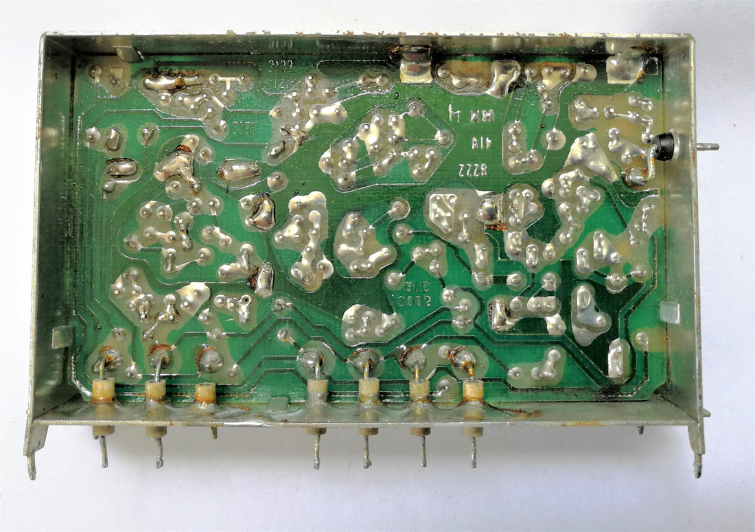
Solder side of the ELC3082 tuner.
|

Interior view of the ELC3082. In the upper right corner the additional BF324 IF amplifier is visible.
|
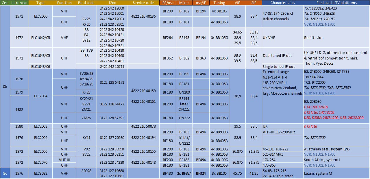
Overview of the Philips ELC2000 tuner family. Although initially used in B&W sets only, towards 1980 it was increasingly used in CTV too (red). This was the last transistor-only generation. Note that the ELC3082 re-introduced PNP transistors (bold). Production codes refer to the factories Stockton-on-Tees (BB), Dunfermline (BY), Brondby (KF), Wesel (KY), Manaus (SR), Singapore (SV), Valkenswaard (TV9) and Barcelona (ZM).
Summary
Compared to the first 15 years of television tuners, covered in parts 1 and 2 of this story, the third phase was much more exciting. Developments in the first phases were gradual but consistent, mainly driven by step-wise improvements in the valves, and not resulting in dramatic changes of the tuner appearance. From 1965, with the introduction of the germanium RF transistor, the tuner quickly changed form factor, allowing for multiple parallel developments, despite Philips being a single company. These developments were, as we've seen, mainly driven by the ease-of-use of the tuner, and especially the ability to store the pre-set values of channels. In the purely mechanically operated valve tuners the Memomatic pre-set storage was the best possible solution, but with the smaller form factor of transistor tuners the mechanical push-button units with pre-set memory were a big step forward. This was largely driven by the simultaneous introduction of colour TV, which, given its high price, demanded for more "luxury" and preferably remote channel selection systems. In this context it was not the introduction of the transistor, but the appearance of the variable capacitance or varicap diode that allowed the required breakthrough in ease-of-control. With the varicap tuning became an electrical operation, allowing the elimination of the expensive and bulky mechanical channel selection. Developments now went much faster, with every two years, linked to the introduction of a new Philips CTV chassis, improved channel selection and storage features: mechanical pre-set channels, tip touch buttons, and after the introduction of the first ICs, electronic search and storage of tens of channels, that could be selected using RC5 remote controls. Essentially the way we operate our TV's today has not changed since the 1983 K30 and K35 chassis! (Of course the internal electronics did, but not the remote control, scanning and program storage look and feel for the user.) And with the ELC2004 the form factor of the tuner had become what it would be for the following 30 years: a folded and plated tin can, with side RF pins/connectors, a bottom row of solderable pins for PCB mounting, containing an electrically tuned channel selector covering VHF and UHF. It had taken 30 years and some eight tuner generations to reach this point
Finding all details about the different tuners was not easy for this period, the "dark ages" of tuner development between roughly 1964 and 1974. In many case I initially had not more information than the service 12nc and the pinning, with occasionally a picture or another snippet of information. So the initial reconstruction of the tuner generations was thus largely my own interpretation, without the claim that this was entirely correct nor perfect. It was only after I received two boxes full of samples from Oswald Moonen and Ite Weide that I was able to make a more reliable reconstruction. These samples resulted in a much more solid description of the V6/U6-V7/U7, VD1/UD1 and early V300/U300 generations, supporting the old motto "Hardware is everything". The support of David Norton and discussion on the several forums have equally allowed a better description of the French and British tuner developments. And with the stories of "old tuner hands" Hugo Duran, Jan van Daal, Peter Boekesteijn and Johan Bos I was finally able to reconstruct the initially very mysterious Elcoma-period, when there were multiple parallel tuner development groups.
Finding all details about the different tuners was not easy for this period, the "dark ages" of tuner development between roughly 1964 and 1974. In many case I initially had not more information than the service 12nc and the pinning, with occasionally a picture or another snippet of information. So the initial reconstruction of the tuner generations was thus largely my own interpretation, without the claim that this was entirely correct nor perfect. It was only after I received two boxes full of samples from Oswald Moonen and Ite Weide that I was able to make a more reliable reconstruction. These samples resulted in a much more solid description of the V6/U6-V7/U7, VD1/UD1 and early V300/U300 generations, supporting the old motto "Hardware is everything". The support of David Norton and discussion on the several forums have equally allowed a better description of the French and British tuner developments. And with the stories of "old tuner hands" Hugo Duran, Jan van Daal, Peter Boekesteijn and Johan Bos I was finally able to reconstruct the initially very mysterious Elcoma-period, when there were multiple parallel tuner development groups.
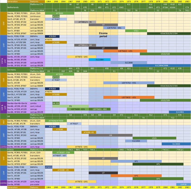
Overview of the Philips tuners used in the period 1964-1983. Since the introduction of new tuners was often linked to the launch of a new (Colour) TV platform, the chassis names have been indicated too. Furthermore, the coloured bar from 1970-1973 indicates the period most of the tuner organisation was part of the HIG Elcoma.
At the same time it was a hectic period, with many parallel developments in the technology domains of television, often influencing each other: introduction of colour TV, migration to transistors, quickly followed by the first ICs, the first steps towards digitization of controls including the RC5 remote control and micro-controller based channel memories, and of course the introduction of varicaps and the first combo VHF-UHF tuners. So from that perspective it is not entirely surprising that the tuner also underwent quite some changes, although we see that at the end of the period, after 1975, it all stabilized with the V314/15/17-U322/42 and ELC2000/2004 families, which both lived quite some years. From here on, especially based on the excellent Elcoma/Components data books, it will all be much more transparent. For that, please read part 4!
References pt3
For this chapter I had to source information quite differently from the previous chapters, but was lucky to find some real valuable ones:
No information nor most of the pictures on this site are copy-righted, and can thus be used freely. However, if text, drawings and drawings modified by me are used, it is appreciated if a reference to my site is included.
- Former Philips and NXP colleague Oswald Moonen, a real collector of lots of stuff, borrowed me all Elcoma/Components tuner data books. Later I obtained the 1981 and 1987 books from Ite Weide, making the series (almost?) complete.
- Philips Elcoma Data Handbook Components and Materials Part3 (CM3) "Radio, Audio, Television", January 1969
AT6381-AT6386, AT7650, AT7652, AT7672, AT7680 - Philips Elcoma Data Handbook Components and Materials Part3 (CM3) "Radio, Audio, Television", February 1972
AT6382, AT7650, AT7672, ELC1004, ELC1024, ELC1034, ELC1054, ELC2000S - Philips Elcoma Data Handbook Components and Materials Part3 (CM3) "Radio, Audio, Television", June 1973
ELC1042, ELC1043, ELC2000S, 12ET5632, 12ET5732 - Philips Elcoma Data Handbook Components and Materials Part3 (CM3) "Radio, Audio, Television", January 1977
ELC1042, ELC1043, ELC2000, ELC2060, ELC2070, ELC3082, 12ET5632, 12ET5732 - Philips Elcoma Data Handbook Components and Materials Part3a (CM3a) "FM Tuners, Television tuners, Surface acoustic wave filters", September 1978
ELC1042, ELC1043, ELC2004, ELC2060, ELC2070, ELC3082, U321, U322, V311, V314, V315 - Philips Elcoma Data Handbook Components and Materials Part2 (C2) "FM Tuners, Television tuners, Video Modulators, Surface acoustic wave filters", June 1981
ELC2004, ELC2006, ELC2060, ELC2070, ELC3082, U321, U322, U323, U341, U342, UF5, V311, V314, V315, V317, V334, VF5, REMO100/200, REMO101/201, REMO301 - Philips Elcoma Data Handbook Components and Materials Part2 (C2) "Television tuners, Video modulators, Surface acoustic wave filters", December 1982
ELC2004, ELC2006, ELC2060, ELC2070, ELC3082,U323, U341, U342, U411/412, UV411-UV416, V311, V317, V334, UF5, VF5, UVF10 - Philips Elcoma Data Handbook Components and Materials Part2 (C2) "Television tuners, Coaxial aerial input assemblies, Surface acoustic wave filters", 1985
ELC2004, ELC2006, ELC3082, M33/34, U341-Mk2, U342, U411/412, U417/418-Mk2, UV431, UV461/462, UV471, UVF10/10A, V317, V334, V431, VF5 - Philips Elcoma Data Handbook Components and Materials Part2 (C2) "Television tuners, Coaxial aerial input assemblies, Surface acoustic wave filters", 1987
ELC3082, FE617/618Q, M33/34, U341-Mk2, U342, U343/344, U411/412,, U743/744, USF10, UV411/412, UV411HKM, UV417/418-Mk2, UV431, UV461/462, UV471/472, UV615, UV617/618, UV627/628, UV635/636, UVF10, V431 - Philips Display Components Data Handbook "Television Tuners, Coaxial Aerial Input Assemblies" (DC03), 1990
- Philips Display Components Data Handbook "Television Tuners, Coaxial Aerial Inputs Assemblies" (DC03), 1992
- Philips Elcoma Data Handbook Components and Materials Part3 (CM3) "Radio, Audio, Television", January 1969
- Another indispensable source of knowledge for TV service manuals and circuit diagrams is "Nostatech's collection and free service manuals" of Wil Manshande, which contains (almost) all Philips TV documentation of the CTV period.
- More useful sources of Philips Service Manuals
- Philips Service Documentation Radio-Television-Tape Recorders 1963, 1964, 1965, 1966 and 1967 (private collection)
- www.Radiomuseum.org, especially useful for German sets
- Nederlandse Vereniging voor de Historie van de Radio NVHR
- And then there are multiple forums with relevant discussions
- Nederlands Forum over Oude Radios
- Nederlands Transistorforum
- Circuits Online, where especially Maarten Bakker is active in analysing 12nc's and factory codes
- UK Vintage Radio Forum , Repair and Restoration
- UK Vintage Radio and TV Repair site (Vrat2.0); also contains some Service Manuals
- Rétro forum, le forum des Radiofil; quite some discussions about Philips sets.
- Pictures of TV's, especially the interior
- Marcel's TV Museum remains a rich source, which he allowed me to use abundantly, so you see quite some pictures from his collection of TV sets;
- Obsolete Telly Museum; contains pictures of quite some Philips sets, although the owner copies and steals complete pages from mine and other's sites, unfortunately. Despite that still a useful source.
- Marcel's TV Museum remains a rich source, which he allowed me to use abundantly, so you see quite some pictures from his collection of TV sets;
- Miscellaneous sources:
- Philips Valvo Brief "Si-PNP-HF Transistoren für VHF/UHF-Fernsehkanalwähler", December 1978
- Philips Valvo Brief "Si-PNP-HF Transistoren für VHF/UHF-Fernsehkanalwähler", December 1978
No information nor most of the pictures on this site are copy-righted, and can thus be used freely. However, if text, drawings and drawings modified by me are used, it is appreciated if a reference to my site is included.
Update history
|
April 2018 First Upload
July 6, 2018 After the first upload of pt.3 I received a lot of additional information, the - literally - largest of which was a big box full of tuners from Oswald Moonen! This included unique samples of some tuners covered in pt3, which has allowed me to update the associated chapters:
|
The big box full of tuners, on loan from electronics collector Oswald Moonen.
The box of tuners kindly given to me by Ite Weide.
|
So, with the samples of Oswald and Ite I have now all of a sudden an almost complete coverage of samples of the tuners in this chapter! As a consequence the following updates and modifications have been implemented:
December 2018
I was very happy to receive V6M, V7M and U7 samples from Jac Janssen, which have helped to clarify quite some open questions around these families. Plus nice pictures.
July 2019
Long discussions with former tuner colleagues has finally clarified the many questions I still had around the tuner organization, especially during the so-called Elcoma period. Peter Boekesteijn (tuner designer, who joined the Edens lab in 1965!), Hugo Duran (mechanical designer, who joined the Bender group in 1972), Jan van Daal (electrical designer, who worked in the Valkenswaard tuner production from 1968 and joined the Bender-group in 1973) and Johan Bos (Tuner Development manager in Eindhoven since 1979 and Singapore 1990-1993) have shed a lot of light on this matter. So especially the sections on the organization and the Elcoma period have been re-written.
Hugo Duran also possesses a unique sample of the thick film tuner prototype, a model never taken into production, on which I've added a section.
October 2019
Peter Burgstaller, one of the really old hands in the BU (started as engineer December 1968, worked in the Magnavox tuner development, started Singapore tuner development where he worked three times, former development manager in Eindhoven and Krefeld) has given a lot of details on the 1970s period, including the thick film tuner he worked on.
I have added a short section on the UVC2 UHF-VHF converter that Ite Weide has given to me. A nice addition, containing one of the very first transistor UHF tuner modules.
July 2020
I've been pointed at the French site Retronik.fr, which contains many old data sources. In there I found a number of Philips RTC (La Radiotechnique-Compelec, de French branch of Elcoma) data books, containing French tuners:
March 2021
Have added additional text and pictures in the section on Colour TV development. Also based on the K4 21KX100 set that Taco Vonk allowed me to photograph.
Re-arranged and mostly enlarged pictures. Have updated all product tables.
August 2021
Some additions and corrections based on feedback Maarten Bakker.
Have added for every tuner family representative TV chassis pictures, mostly from Marcels TV Museum and Radiomuseum.org.
October 2022
Small additions and corrections to the 1976 thick film tuner development by Peter Boekestein.
Links to the ultra-sonic remote control development added.
October 2023
Linked to the release of the first volume of the Philips Television Tuner history, this page has been reduced to the core tuner story. All stories detailing the underlying technologies or the applications can be found in the book.
- The U6/V6 and VD1/UD1 sections have been completely re-written, deleting the original V301/U301 generation that never existed.
- I have added a dedicated section on the migration from mechanical to electrical channel selection methods.
- Most sections have been extended with many pictures of the relevant tuners, based on the samples from Oswald and Ite.
- I have added sections on the French and British tuner developments, based on David's inputs and discussions on the French Rétro-Forum.
- Have added a section on the tuner factories 1965-75, since this was a time of quite some extensions and I concluded the next chapter was to late to discuss them.
December 2018
I was very happy to receive V6M, V7M and U7 samples from Jac Janssen, which have helped to clarify quite some open questions around these families. Plus nice pictures.
July 2019
Long discussions with former tuner colleagues has finally clarified the many questions I still had around the tuner organization, especially during the so-called Elcoma period. Peter Boekesteijn (tuner designer, who joined the Edens lab in 1965!), Hugo Duran (mechanical designer, who joined the Bender group in 1972), Jan van Daal (electrical designer, who worked in the Valkenswaard tuner production from 1968 and joined the Bender-group in 1973) and Johan Bos (Tuner Development manager in Eindhoven since 1979 and Singapore 1990-1993) have shed a lot of light on this matter. So especially the sections on the organization and the Elcoma period have been re-written.
Hugo Duran also possesses a unique sample of the thick film tuner prototype, a model never taken into production, on which I've added a section.
October 2019
Peter Burgstaller, one of the really old hands in the BU (started as engineer December 1968, worked in the Magnavox tuner development, started Singapore tuner development where he worked three times, former development manager in Eindhoven and Krefeld) has given a lot of details on the 1970s period, including the thick film tuner he worked on.
I have added a short section on the UVC2 UHF-VHF converter that Ite Weide has given to me. A nice addition, containing one of the very first transistor UHF tuner modules.
July 2020
I've been pointed at the French site Retronik.fr, which contains many old data sources. In there I found a number of Philips RTC (La Radiotechnique-Compelec, de French branch of Elcoma) data books, containing French tuners:
- "Guide de l'ingénieur, Radio-Television-Musique", RTC La Radiotechnique-Compelec, 1970
ELC1054, service tuners ST5203 (V5B) (versions with E and P-series valves), ST5156 (V5T), AT6383/30 (U5) - "Guide de l'ingénieur, microélectronique", RTC, 1977.
Especially useful for an overview of IC technology at the time - "Sous-ensembles Télévision-Radio-Musique", RTC 1978
UF1, VF1, and service tuners AT6382/30 (U5), LT23C UHF preset module with UF5, ST5398 (UV1)
March 2021
Have added additional text and pictures in the section on Colour TV development. Also based on the K4 21KX100 set that Taco Vonk allowed me to photograph.
Re-arranged and mostly enlarged pictures. Have updated all product tables.
August 2021
Some additions and corrections based on feedback Maarten Bakker.
Have added for every tuner family representative TV chassis pictures, mostly from Marcels TV Museum and Radiomuseum.org.
October 2022
Small additions and corrections to the 1976 thick film tuner development by Peter Boekestein.
Links to the ultra-sonic remote control development added.
October 2023
Linked to the release of the first volume of the Philips Television Tuner history, this page has been reduced to the core tuner story. All stories detailing the underlying technologies or the applications can be found in the book.