Introduction
|
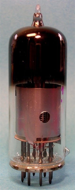
It was only when researching the work of my father as a young engineer that I realised the recurring appearance of the EQ40 tube. When looking further into the specifications and applications of this tube it becomes clear this was one of the ultimate vacuum tube developments for consumer applications. With its nine electrodes (and therefore an 'enneode') it was the most of what could be achieved of functional integration into one glass-bodied vacuum tube of the standard Rimlock (40) or Noval (80) series. I will therefore try to picture the history of this tube, from its development to introduction and applications. Into this story I will regularly mix the activities of my father, Piet Hooijmans, when he was working for the Philips Radiobuizen Laboratorium 1 [Radio Valves Laboratory 1] in Eindhoven because this period coincided with the heydays of the EQ80 development. Part of his heritage are the following documents or books from which I obtained most of the data presented:
|
Chapter navigation
|
Basic FM Detection
Right after the second world war FM (Frequency Modulation) became available as an improved sound modulation system compared to the up to then standard AM (Amplitude Modulation). FM has much better noise performance and is less vulnerable to interference. FM was targeted for both the emerging PAL television standard as well as for standard radio transmission. In The Netherlands, driven by Philips who wanted to demonstrate these new technologies in their home country, commercial television was introduced in 1951 (after experimental transmissions had started in Eindhoven in 1948) while the first FM transmitter came on-air in 1954 (in Hulsbergen, near Maastricht). In the years preceding these introductions Philips, as the leading European vacuum tube supplier, was very active developing the required tubes and circuits for the FM receivers. This is where the EQ40 comes in.
|
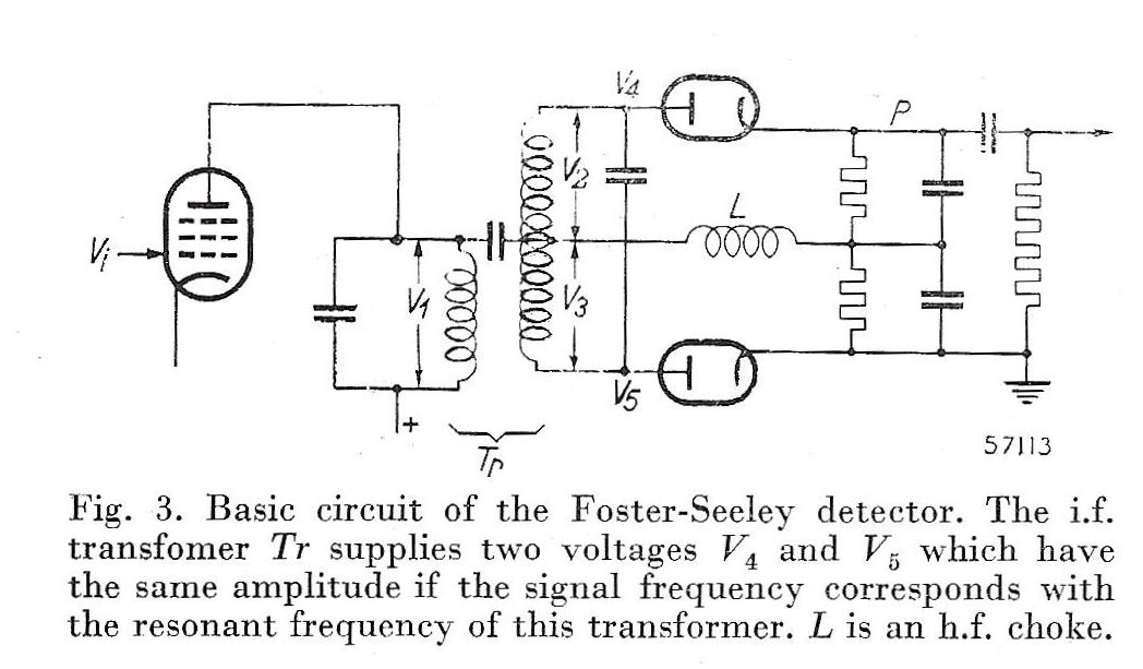
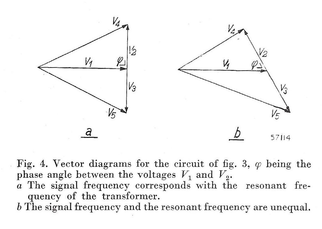
Before the introduction of the EQ40 as FM detector, the only practical method for FM-detection was the Foster-Seeley frequency discriminator. This concept uses a resonant circuit, tuned to the central intermediate frequency of the FM signal where the anti-phase signals at both ends (V4 and V5) are each peak-detected by a diode and their outputs subtracted. Typically an EB41 dual-diode would be used in this circuit. When the input signal is equal to the centre frequency of the resonant circuit the two output signals are equal and in anti-phase and the output is zero. But when the instantaneous frequency deviates from the centre frequency the vectors V2 and V3 will rotate around V1, resulting in V4 and V5 of different amplitude. The result is a sine-shaped detection curve around the centre frequency, which can be approximated as linear for limited frequency excursions around the zero-crossing.
This immediately also explains the main drawback of this detector: there is no active element involved, and the conversion gain is therefore low. Furthermore when the input signal amplitude V1 changes this immediately translates into amplitude variations of the output, so-called residual AM. For optimum detection of an FM signal the amplitude should be constant to avoid AM-to-FM distortion, and the Foster-Seeley discriminator thus requires a limiter. This could be obtained using local feedback, but that in turn results in reduced sensitivity. It is not entirely surprising that Philips was looking for an active FM detector with better performance than the passive Foster-Seeley. However, this is the technical story. There are persistent stories on the radio history forums were it is stated that Philips developed an alternative concept to avoid paying patent royalties to RCA (or its European license holder Telefunken), which had acquired the patent from Foster and Seeley. Knowing Philips this is a very realistic assumption. |
The EQ40 phi-detector
|
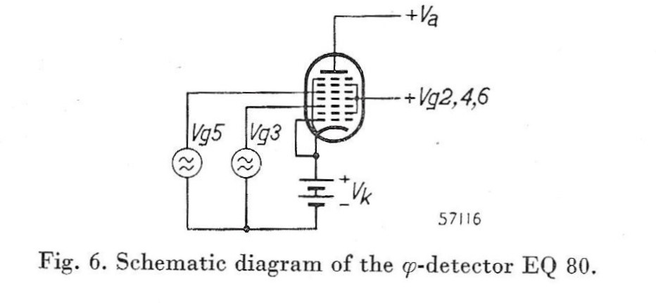
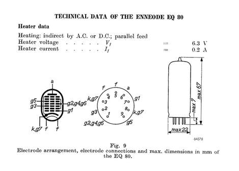
Conceptually the EQ40 enneode can best be pictured as two stacked pentodes. Electrons emitted by the cathode initially pass through the first two grids g1 and g2. The first control grid g3 for the first signal determines what the electrons will do next. If the g3-voltage is negative the electrons will be reflected and absorbed by g2. If g3 is positive, however, the electrons pass g3 and g4, where at g5 the same happens based on the second input signal. Grid g4 has the same function as g2, while g6 and g7 are the classical pentode screening grids to suppress secondary emission. The net effect of all this is that the electron beam only reaches the anode when BOTH g3 and g5 are positive:
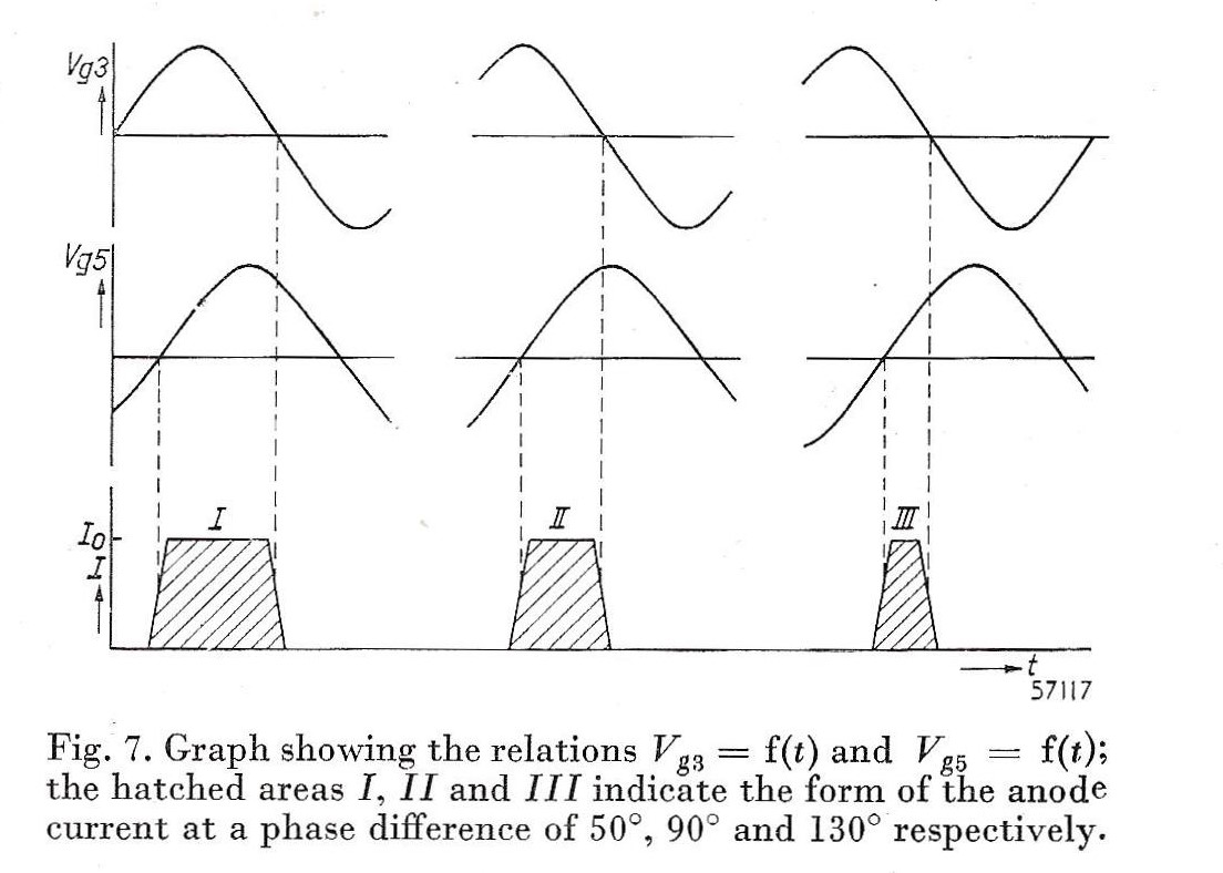
In essence, the EQ40 can be considered as two stacked (or series connected) pentodes. Where each pentode is not steered on its first grid g1 as is normally done in linear amplifiers, but on the screening grids g3 and g5. The resulting Vg-Ia characteristic of each pentode section is identical to that of a diode. For Vg larger than the knee voltage the anode current is then essentially independent of the input voltage. The EQ40 is thus principally operated in the saturated regime, linked to the FM detection which needs to suppress AM as much as possible. Under that condition the tube can be considered to be an (analogue) AND-gate; only if both inputs are high the output is high, see Fig. 7. This concept is also known as the coincidence detector, because the output is only positive when the two control gate voltages coincide.
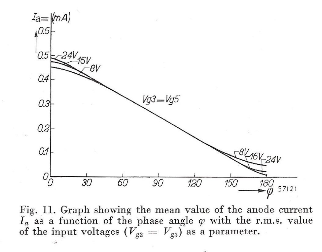
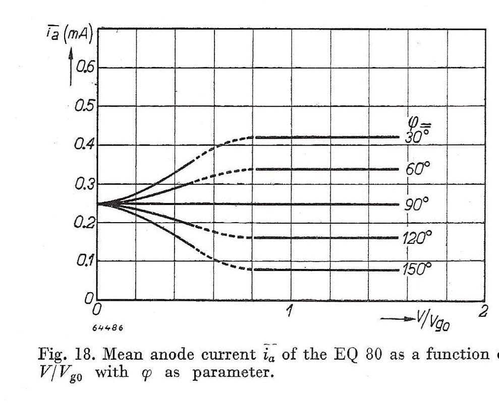
It is now also clear why Philips baptised EQ40 as "Phi (phase) detector". When two sine waves of identical frequency are applied to grids g3 and g5 the average anode current is proportional to the phase difference phi. When the phase difference is zero the two sines overlap and during the positive half cycles the maximum anode current flows. Interestingly, the relation between the phase difference and Iout is not a sine-curve, as for the Foster-Seeley detector, but in contrast (and much more ideally) linear for phi between 0 and 180 degrees (and 180 and 360), see Fig.11. Another way of visualising this detection behaviour is Fig.18, showing the anode current as a function of the relative grid voltages on g3 and g5 and the phase difference. Vg0 is the grid voltage above which the anode current essentially becomes amplitude independent, around 14V. This is then immediately one of the biggest weak points of the EQ40: it requires a relatively - compared to most other tubes in the regular TV receiver line up - high grid voltage. The EQ40 therefore requires a driver stage able to generate these voltages, often an EF42 pentode. But then again, because of the high-ohmic load of the driver and the high conversion gain, the EF42 can provide a large voltage gain, and thus only requires a low input voltage. Overall the (EF42) input to (EQ40) output conversion gain is very high, and in all cases much higher than the passive frequency detectors.
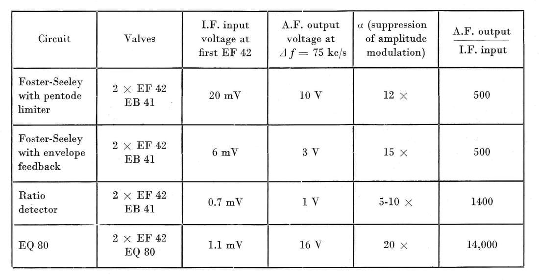
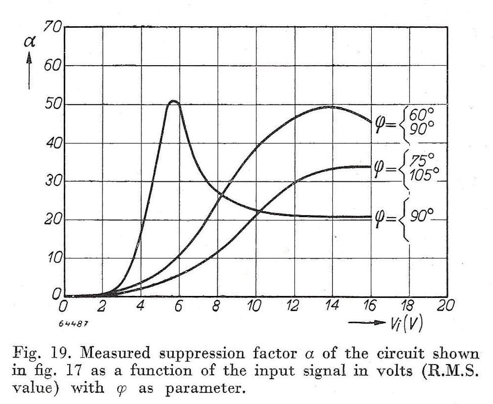
At the same time, once this Vg>Vg0 condition is fulfilled, the EQ40 has the major advantage of becoming amplitude independent, or in other words it provides a good limiter function that is normally desired for FM detection. The AM-suppression index alpha is thus also very high, see Fig.19. Again this graph confirms that for Vi=Vg larger than Vg0=14V the AM-suppression is very high. Overall the EQ40 had a lot of advantages when introduced, summarised in below table, and Philips made quite some publicity from 1949, the year it was officially launched as a product. |
The launch of the EQ40/EQ80
|
While the Radiobuizen-lab engineers were busy optimizing the applications of the EQ40, in parallel another development took place. One of the major breakthroughs that made Philips the leading valve supplier was the development of the all-glass valve. Up till the end of the 1930's most valves still had complex metal or hybrid bases where the external leads protrude through the valve body. Most of these constructions were bulky, expensive and not easy to produce in volume. Already in 1935 Philips started the development of an all-glass valve base, which resulted in the EF50 pentode. For a very detailed history on the EF50 development and its application in the first British radar systems, see the fantastic story by my friend Ronald Dekker on his web site. After the war Philips picked up this development by introducing the Rimlock series of valves, also known as the 40-series. These tubes had 8 pins regularly spaced on a circle, while the reference (to distinguish which was pin #1) was a so-called "pimple" on the outside of the base rim. This pimple fitted into a slot of the Rimlock valve holder on the equipment chassis.
All this is nicely visible on the left picture of the EQ40. At the base, clearly all-glass with the eight 1mm thick chromium-iron pins at the bottom. (This metal alloy was selected for optimum sealing with the glass once hardened, providing a leak-free connection that maintained the valve vacuum). The pimple is visible on the right of the base rim. The first Rimlock valves, although using the all-glass base, often still had an additional metal ring around the base, giving them an appearance more like the older style valves. The EF42 is an example of these. However, later this metal ring was dropped and the really all-glass types took over. The EQ40 was one of these, although the EF42 later also joined the family. Although much cheaper and easier to produce than the older generations, the Rimlock series was not the final development of high volume valves. Essentially the "pimple" and the special valve base made it expensive, and therefore the internationally standardized Noval base was introduced. This had a 9-pin configuration, arranged in a circle with 10 positions where the 10th place was left empty for the pin referencing. Philips coded these valves with numbers in the 80 range (and when they ran out of numbers it became the 180- or 800-range in the sixties). Already by the end of the 1940's, around 1948-49, the Noval series very quickly started to replace the Rimlock series. And this also happened to the EQ40. Whereas my father in the Radiobuizen-lab was still building all its radio and television prototypes based on the EQ40 and other valves from the Rimlock series, in all products and in the official announcement and application notes of the valve it was from now on the EQ80. Because the EQ80 base offered one additional pin compared to the 8-pin EQ40 base, the cathode-g7 contact was duplicated for ease of application. |
|
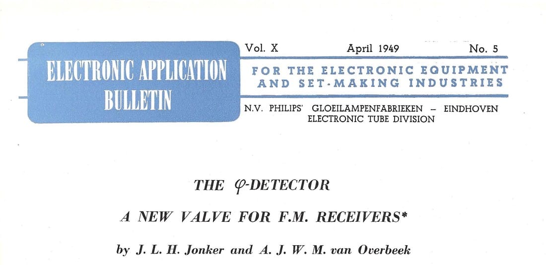
The EQ40 was formally launched in April 1949, when a first article appeared in the Philips Electronic Application Bulletin (EAB) targeted at the internal Philips set development organizations: "The phi-detector, a new valve for FM receivers" by Jonker and van Overbeek. Hans Jonker (1901-1963) was the founder of the Buizenlab (Valves Lab) in 1931, but had returned to Philips Research (the NatLab) to head the very important Research group on valve development. In Philips Research it was standard practice that for important inventions the group leaders were the lead authors, even though the work might have been done by others. In this case the main inventor, or at least the engineer that worked out the details of the new valve, was Van Overbeek from the group of Jonker. The elaborate 9-page article describes in detail what has been summarised above on this page.
In July 1949 the same two authors publish a second article in the Philips Technical Review, a public journal: "The "phi-detector", a detector valve for frequency modulation". Although the basic story from the EAB article is of course repeated, this article focuses much more on the circuit design and detection basics of the valve. |
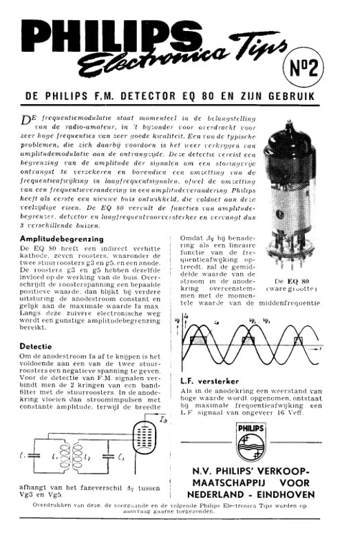
The EQ80 has for a number of years been the flagship valve of the Electron Valve Division. So when e.g. Philips started to structurally advertise in Electron, the monthly magazine of the Dutch radio amateur organization, one of the very first components presented was the EQ80 in September 1950. [Electron on-line archive]
|
Right after the war Philips was very much focused on the Dutch, Belgian, German, British and French markets, especially for its introduction of Television. The EQ80 was consequently also produced by and licensed to the local Philips subsidiaries, e.g. Mullard in the UK and Valvo in Germany, although as far as can be seen only Philips in Eindhoven and Philips-Valvo in Hamburg produced the valve. Although details are scarce, it seems that both Siemens and Telefunken re-sold the valve labelled as their own, probably to complete their offering. A derived version was launched as the UQ80, in the U-series with 0.1A heater current. Compared to the EQ80 (6,3V-0,2A) the UQ80 had a 12,6V heater supply voltage. As it looks the UQ80 version was hardly used if at all; I haven't found a single trace of it in practical sets. Finally, Philips registered the EQ80 according the US coding system as 6BE7, although no applications under this name are known either.
The EQ40 as FM-detector
The most urgent application of the EQ40/EQ80 was the Television Receiver, because Philips really wanted to push that technology to avoid competitors taking the lead in this new application. As said earlier, the new 625-line "Gerber norm" TV standard used FM for the sound carrier, and thus an FM-detector in the receiver.
The first thing that needs to be done in an FM-detector based on the EQ80 phi-detector is to convert the instantaneous frequency modulation into a phase difference phi. This can be done with a double tuned bandpass filter centred at the intermediate frequency. At the two outputs the signals still contain the original frequency modulation, but now including an instantaneous phase difference phi which varies (almost) linearly with the instantaneous (audio) input frequency.
The first thing that needs to be done in an FM-detector based on the EQ80 phi-detector is to convert the instantaneous frequency modulation into a phase difference phi. This can be done with a double tuned bandpass filter centred at the intermediate frequency. At the two outputs the signals still contain the original frequency modulation, but now including an instantaneous phase difference phi which varies (almost) linearly with the instantaneous (audio) input frequency.
|
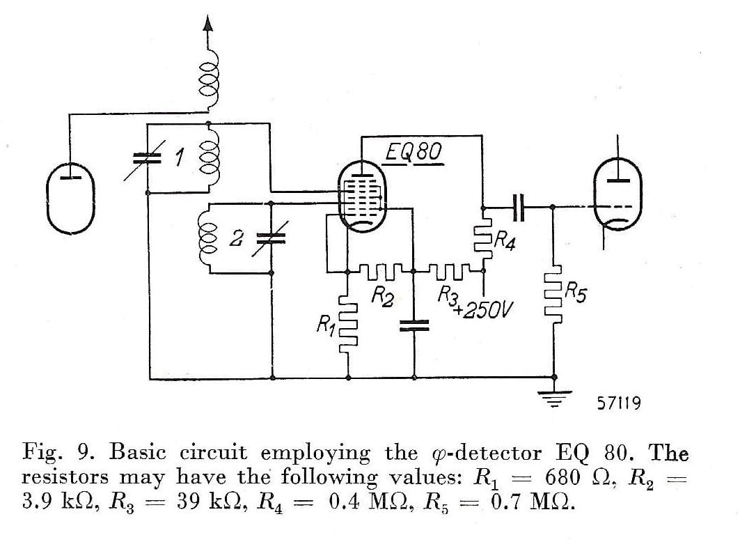
The EQ80 will now translate this phase difference phi into an anode current variation as described earlier, where the output signal is identical to the original audio modulating signal. The circuit concept is shown on the right, where 1 and 2 are the two tuned branches of the double-tuned BPF. The anode current essentially exists of very short pulses with a repetition frequency identical to the instantaneous intermediate frequency (see Fig7 above) and a width determined by phi. The output load circuit, which is R4 in parallel with the anode-to-ground parasitic capacitance, will act as a low pass filter and filter out the IF and its harmonics, leaving only the detected audio signal at the input of the next stage. The most uncommon element in the reference design are the resistors R2 and R3, which provide a DC-path between g2-g4-g6 and the cathode. Below is explained where they come from.
|
Optimization of the EQ40
|
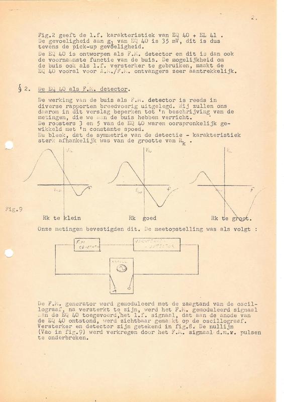
One of the most interesting aspects of the EQ40 that I stumbled upon was the apparent optimization that took place before its final release, and the involvement of my father in that process. It has to do with two aspects of the valve: its internal construction and the application. (Probably) early 1948 my father, under the supervision of his boss Dr. B. (Bert) Dammers, was working on the optimization of FM detection with the then EQ40. For details of their work see Report 2 "Description of an AM/FM receiver" from March 1949. The valve was used initially for an FM radio receiver frequency detector according the principles explained above. When measuring the FM detector, they found a large spread in the FM detection curves. This was traced back to the control grids g3 and g5 having a constant grid winding speed, which lead to significant differences in the zero-crossing and asymmetry of the FM-detection curve. The zero-crossing could be corrected by adjusting Rk, the series grounding resistance of the cathode, but the optimal Rk showed a spread of ±35% (3600 ± 1200 Ohm measured on 26 tubes). As root cause the spread of the internal contact potential of the tubes is mentioned. This was solved by connecting the cathode through a voltage divider (R3-R2 in Fig9) to the screen grids (g2-g4-g6), providing a bias current through Rk that is dependent on the screen grid voltages. In this way the tube DC biasing became less tube-dependent, and the cathode resistor value for optimal detection would require much lower spreads (560 ± 50 Ohm, so less than 10%).
Next the combined FM and AM detection characteristics were measured. It was found that for the setting as determined above where the FM-detection curve was perfectly symmetrical (Rk at 500Ohm), residual AM-sensitivity was high (still 250mV at the anode). For the setting of minimal AM detection (only 30mV at the anode) the Rk had to be increased to 160Ohm. It then says: |
|
These measurements were based on tubes with so-called constant winding speed (“spoed” in Dutch) of the control grids g3 and g5. Therefore the tubes have been changed based on variable winding speed control grids. This gives a lower slope of the characteristic, with a less annoying influence on the AM detection. This is explained in the release report of the EQ40 by Radio Lab 1.
The sensitivity of the detection characteristic remained, as before, dependent on Rk, but the difference in Rk for minimal AM and Rk for symmetrical FM detection is now much lower: Rk for symmetrical FM detection: 650 ± 70 Ohm (measured on 17 tubes) Rk for minimal AM detection: 685 Ohm with a residual AM of only 12mV [Quote by the authors] From these results the motivation to introduce variable winding speed control grids is sufficiently supported. |
My interpretation from this is that the initial measurements as reported were done on what we would call today "beta versions" of the EQ40 valve. Based on the measurements and analysis of Dammers and Piet Hooijmans in the Radiobuizen 1 application lab, in collaboration with the Radio Lab 1 where the valve was designed, it was decided that the valve was optimized by introducing variable winding speed of the two critical control grids g3 and g5. Although I have no hard proof, I assume that this was then formalised in the tube design, as suggested by the remark related to the Release Report of the EQ40 and the last remark by the authors.
This is further supported by the fact that the official reference design of the EQ40/EQ80 as in Fig9 is 100% in accordance with the recommendation in the report of Dammers and Hooijmans: Rk optimal at 680 Ohm, and the application of a biasing control scheme with the voltage divider R2-R3 providing a feedback current through Rk based on the g2-g4-g6 screen grid voltage. In all further application diagrams these values were used, illustrating the universal adoption of this biasing scheme.
This is further supported by the fact that the official reference design of the EQ40/EQ80 as in Fig9 is 100% in accordance with the recommendation in the report of Dammers and Hooijmans: Rk optimal at 680 Ohm, and the application of a biasing control scheme with the voltage divider R2-R3 providing a feedback current through Rk based on the g2-g4-g6 screen grid voltage. In all further application diagrams these values were used, illustrating the universal adoption of this biasing scheme.
|
While researching this EQ40/EQ80 history and the broader early Philips TV history, another surprising find was that Bert Dammers, the boss of my father while in the Radiobuizen Laboratorium and the co-author of his technical reports, was a very important person in the context of valve developments and their applications. Around 1946 Dammers moved from the Research organization to the Emmasingel to lead the Consumer group within the Radiobuizen-lab. My father was clearly one of the technicians working for him. Details on this period can be found here. Towards the end of the 1950s Dammers succeeded Alma as the head of all Radiobuizen-labs (both consumer and professional), maintaining its role as development and definition centre of active key components. First valves, then transistors and eventually IC's. Throughout the 1960's his organisation was internally known as the "Dammers-lab", and was highly respected throughout the Philips organization. Bert Dammers continued to lead this organization until he probably fell ill and passed away in 1968 at the young age of 58. The Dammers-lab then became the Elcoma Centrale Applicatielab Bouwstenen (CAB) and Philips Components Application Lab Eindhoven (PCALE) and moved to the Beatrix complex on the western outskirts of Eindhoven.
|
The EQ40 and EQ80 used in Television receivers
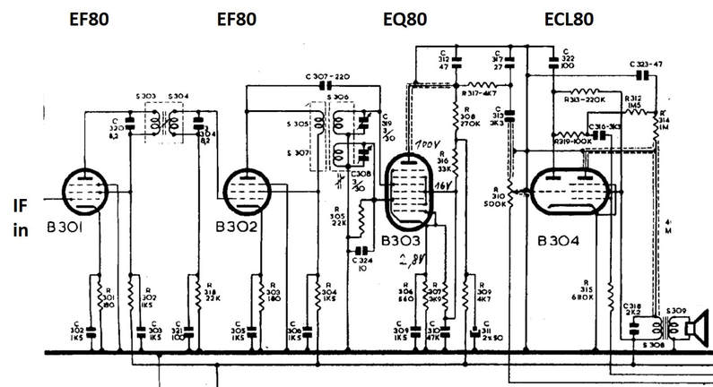
At this stage, it is interesting to explore how the EQ80 FM detector application circuit developed over time. The first topology is the one used in the home-built TV receiver of my father, based on the latest reference design as used inside the Radiobuizen Lab I mid-1948. The circuit diagram of the sound bar is shown below.
Interestingly (or maybe not) the circuit used in the August 1948 home built TV, in line with the latest reference design, is almost identical to the circuit concept of Fig10. Specifically, R1-R4 are all exactly the same value in both implementations. The main differences in my father's TV are (1) a damping resistor of 15k in the g3 tuned circuit (2) an additional anode capacitor to ground of 56pF, likely to give stronger LPF action at the output and (c) insertion of the volume control potentiometer in the anode output.
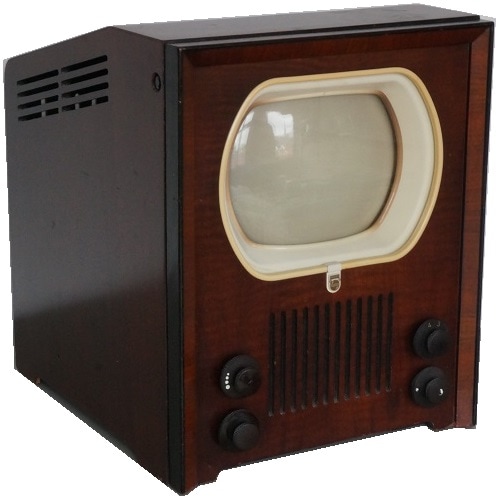
The next instantiation is the Philips TX400U-01, the first commercially produced Philips television set in the Netherlands, launched in 1950, and the first set in the world supporting the new 625 lines CCIR-B system. (The TX500 was launched one year later, featuring a larger picture tube but otherwise identical). The TX400 could receive four channels in the VHF I band (41,25 to 62,25MHz) and used a picture-carrier IF of 23,5MHz. With a picture-to-sound carrier distance of 5,5MHz of the CCIR-B standard, the resulting sound IF was 18,0MHz. Although the component values are not readable from this circuit diagram, conceptually it is still the same basic circuit as in Piet Hooijmans' TV and the published reference designs, but in some ways even further simplified, almost certainly to facilitate manufacturing. All in all one can conclude that the basic application of the EQ80 as television FM detector was stable since 1948, and the basis for all Philips television sets from 1948 till at least 1952.
The next instantiation is the Philips TX400U-01, the first commercially produced Philips television set in the Netherlands, launched in 1950, and the first set in the world supporting the new 625 lines CCIR-B system. (The TX500 was launched one year later, featuring a larger picture tube but otherwise identical). The TX400 could receive four channels in the VHF I band (41,25 to 62,25MHz) and used a picture-carrier IF of 23,5MHz. With a picture-to-sound carrier distance of 5,5MHz of the CCIR-B standard, the resulting sound IF was 18,0MHz. Although the component values are not readable from this circuit diagram, conceptually it is still the same basic circuit as in Piet Hooijmans' TV and the published reference designs, but in some ways even further simplified, almost certainly to facilitate manufacturing. All in all one can conclude that the basic application of the EQ80 as television FM detector was stable since 1948, and the basis for all Philips television sets from 1948 till at least 1952.
|
After the first-generation television receivers TX400/500 the EQ80 was used in one more generation of Philips sets: the TX701 projection TV and the TX1400. The TX700 series used in-cabinet rear projection on a much larger viewing screen. This was undoubtedly an effort to provide larger screens while the technology for direct viewing picture tubes was still in its infancy. A high intensity MW6-2 projection tube illuminated via three mirrors and one lens a 45x34cm screen. Which was at the time (1951) a wide screen! The TV reception chassis inside the TX701 was fully identical to that of the TX400/500, with 23 valves including the EQ80. There was a second chassis with 9 valves providing the 25kV supply voltage for the MW6-2. The TX701 price at introduction was 1390Hfl, quite an amount those days.
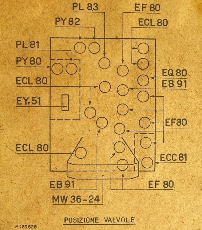
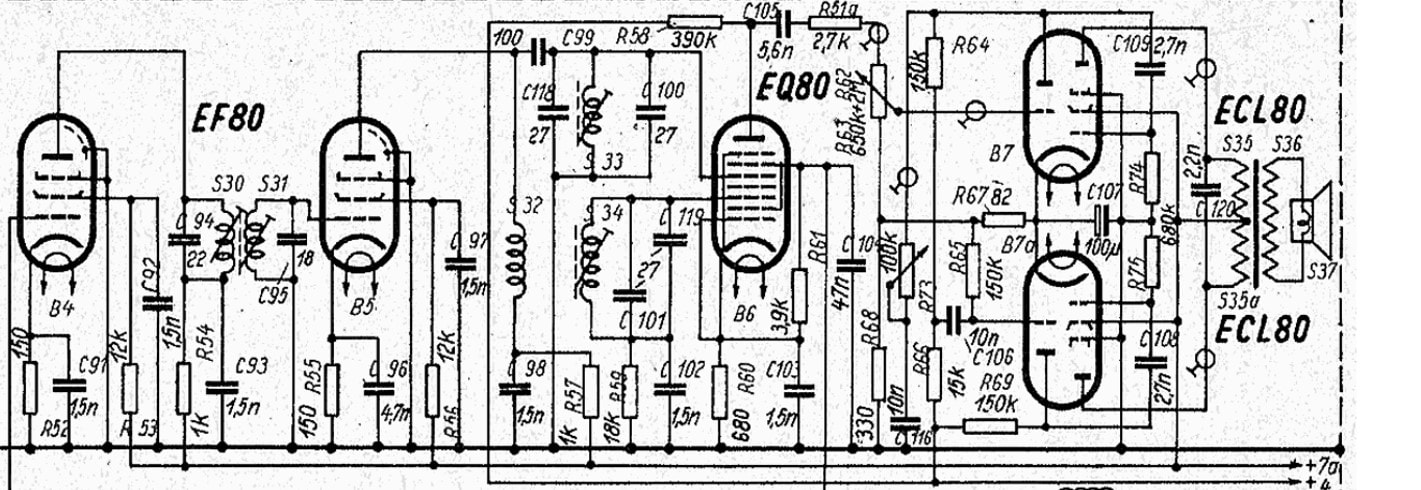
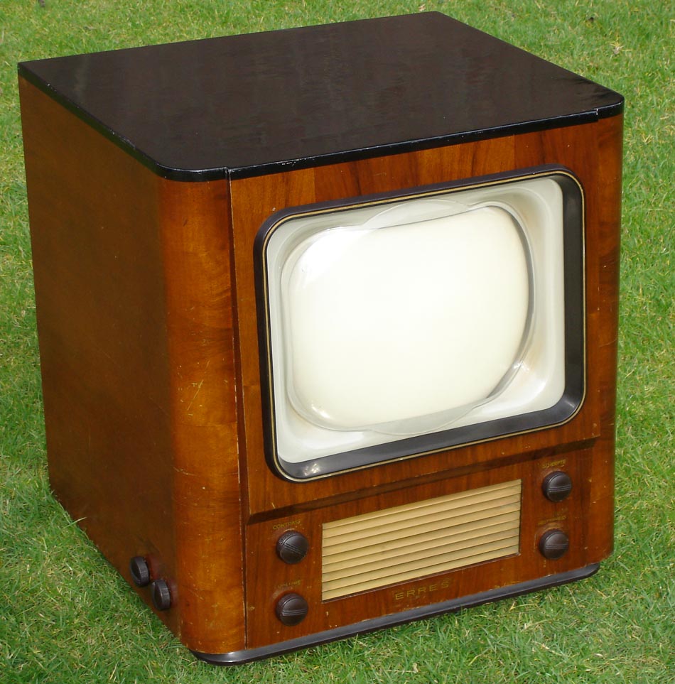
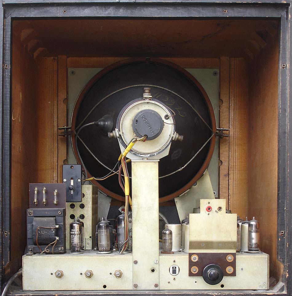
In 1952 the TX1410 and TX1710 were introduced, which were upgraded models. The TX1410/U, the Dutch-produced model but also manufactured in Italy (Monza), was based on the German model TD1410. It had a slightly larger picture tube than the TX400/500, but especially upgraded sound: a balanced audio output stage using two ECL80's plus tone control. For a nice description of this TV set see the Technisch Museum site. The 1410-series (both TX and TD) also introduced the 10-channel (VHF I and VHF III) tuners. An interesting feature, especially used in Germany, was that the set could also receive radio FM transmissions. In that mode the supply to all picture related sections could be switched off. The TD2312 and TD2314 were a next generation rear projection TV, but based on the TD1410 chassis with all features mentioned. The TX1701 was an upgrade of the TX700, while the TX1714 used the new platform. Next to Philips there were a n umber of other manufacturers of TV sets using the EQ80. Most of them were in Germany (Saba, Siemens, Graetz), Switzerland (Albis, a JV between Telefunken and Siemens, Tonfunk) and Italy (Irradio, Magnadyne, Minerva). But interestingly there was also van der Heem, in Den Haag, the Netherlands, bringing out its KY311U under the brand name Erres. (Van der Heem/Erres was for many years an independent competitor of Philips, only to be taken over in 1967, after which date Erres continued to be used as a sub-brand). These were all released in 1952-1955, after that date no more television EQ80 usage is known. Details on all sets using the EQ80 can be found on the excellent site on radio and TV history Radiomuseum. |
|
The EQ80 in radio receivers
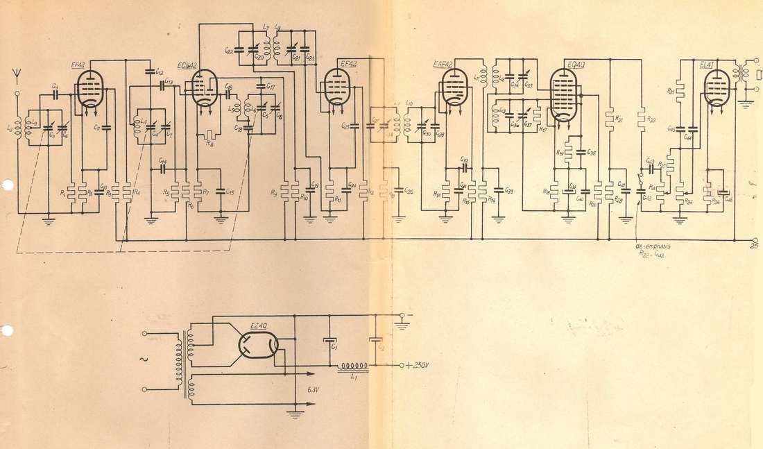
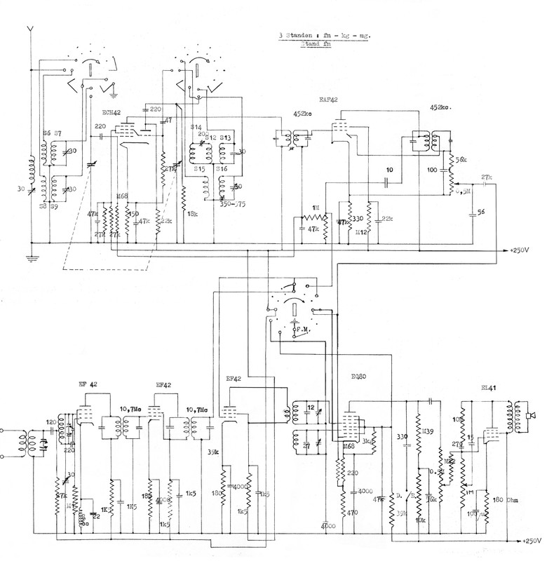
Obviously the EQ80 was also intended as detector tube in FM radio receivers. Here too we can make use of the Philips Radiobuizenlab development report of Bert Dammers and Piet Hooijmans, already quoted earlier in the section of the EQ40 optimization. The reference schematic of an FM receiver was - apart from the RF section with an EF42 and ECH42 mixer-oscillator - very much like that of a television sound chain as described above: an EF42 and EAF42 as IF amplifier, followed by an EQ40 demodulator and EL41 power amplifier. (The additional diode in the EAF42 was not used in FM mode, making it effectively two EF42's as in the TV IF). Below is the circuit diagram of the FM receiver as per Piet Hooijmans' report.
The problem was, however, that in the market there was hardly or no need for FM-only receivers; given the legacy AM transmission any commercial product needed to be combined AM-FM reception. This was exactly the ambition of the project by Dammers and Hooijmans, which they explain as follows:
|
Introduction
The intention was, starting from an FM receiver using the following tubes EF42 - ECH42 - EF42 - EAF42 - EQ40 - EL41 - EZ40 RF mixer 1st IF 2nd IF detector power amp to make this receiver also fit for AM reception. The circuit diagram of the original FM receiver is shown in Fig. 7. In this report we will discuss the IF section, the detector and the LF part of the combined AM/FM receiver. The difficulties in combining AM and FM in the RF and mixer circuits are not yet fully resolved. Plans for further improvements will be indicated. During AM reception the tubes have the following function: EF42 cathode – grid 1 works as AGC diode EAF42 IF and detector EQ40 LF amplifier EL41 power amplifier |
|
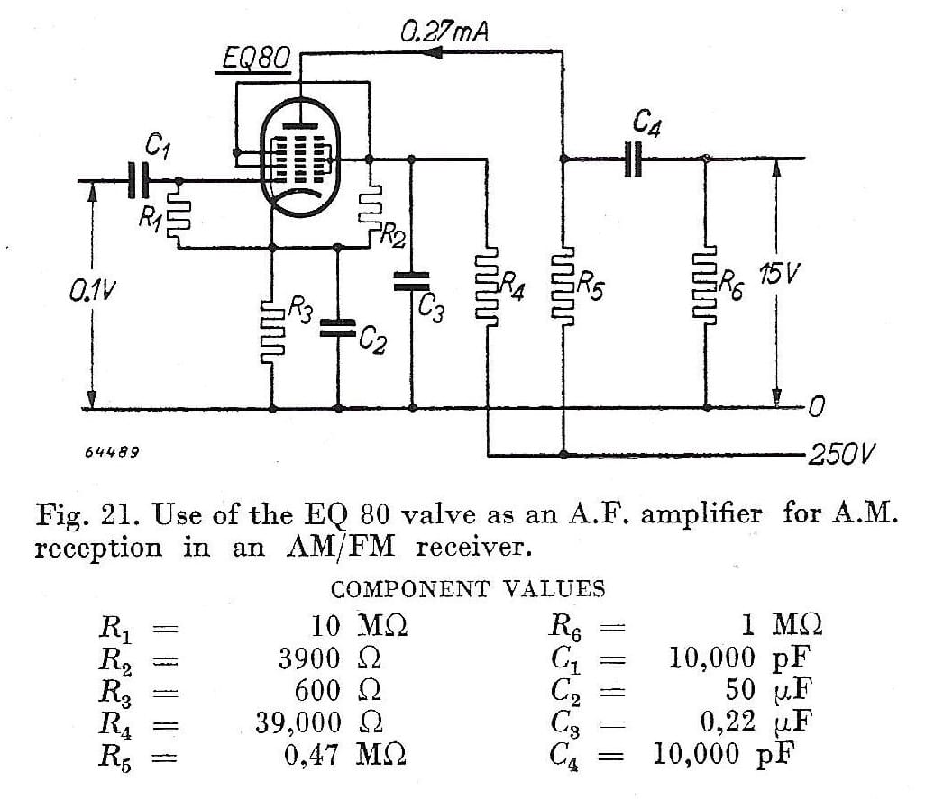
Essentially what they tried to achieve was implementing the combined AM-FM reception without adding valves (to reduce the cost). To this end the AM detection was not done in the EQ40, but used the single diode in the EAF42. Because of the low conversion gain in this peak detection the EQ40 was used as an analogue amplifier. Which was of course an expensive solution, since more than half of the grids in the valve was effectively not used. This is also visible in Fig.21: g3 and g5 (the control grids in case of FM detection) are connected to g2-g4-g6, giving one enormous screen grid g2-g3-g4-g5-g6-g7, reducing the valve to a single albeit expensive tetrode. This was nevertheless seen as a useful application, because it also appeared in the EAB and Philips Review articles.
From the report of Dammers and Hooijmans it becomes clear that trying to make an AM-FM receiver with the limited number of valves proposed was a real nightmare. Although the AM IF (452kHz) and FM IF (10.7MHz) were far apart in the frequency domain such that the resonant circuits for filters could be stacked, there were many cumbersome switching issues. E.g. around the EQ80, where inputs needed to switch from g3 and g5 for FM to g1 for AM. At the end of the report they suggest to fundamentally change the functions of the tubes, depending on the mode. So, in AM the ECH42 would be used as mixer-oscillator, but for FM reception they proposed to use the first EF42 as self-oscillating mixer. They conclude (March 1949) this concept to be very interesting, with lots of potential, but recommend further investigations. |
Investigations have almost certainly continued in this direction, but after dropping the original boundary condition that no extra valves were allowed. Efforts to combine the AM and FM RF and IF sections were given up, and each branch was allowed its own line-up. For AM this were the ECH42 and EAF42, whereas the FM used three EF42's. The EQ40 as FM detector or audio amplifier and the EL41 power amplifier end valves were shared. This information is based on a circuit diagram I found in, but not officially part of, the report by Dammers and Hooijmans, so I assume this was an update from later investigations that my father added to his file. The circuit diagram is shown below. I dare to suggest this was likely the ultimate radio receiver design using the EQ40/EQ80.
|
Undoubtedly based on the work at the Radiobuizenlab, Philips HIG Elektronenbuizen in November 1950 released a booklet on the application of its latest valves for AM/FM radio design: "EF42, EF43, EQ80, EB41 Receiving tubes for FM". Note this was half a year after the release of a similar booklet on Television valves. In it were a number of combo AM/FM radio designs, with different levels of performance (defined as receiver sensitivity at the antenna inputs) and cost (the number of valves). It covered a series of six architectures, ranging from a high-sensitivity 9-valve concept to a 6-valve medium performance. Four of the radios were based on the EQ80 for FM detection, in three cases re-using it as AF amplifier in AM mode.
The most complex design (number I) is apart from some minor details identical to the reference design of Dammers and Hooijmans above: three EF42's for the FM RF-IF chain followed by the EQ80 and an EL41. An ECH42 as the AM mixer-oscillator-IF. The only difference is that the EAF42 has been replaced by an EBF80 and an EM34 tuning indicator has been added. The latter is linked to the introduction of a new concept for FM: Silent Tuning.
|
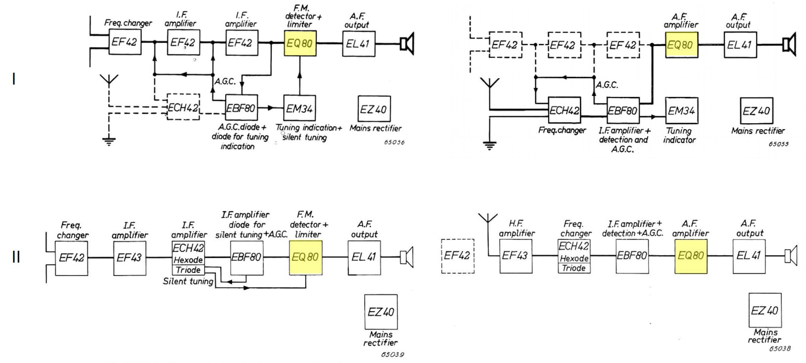
Two of the concepts from the booklet using the EQ80 that have been worked out in detail. On the top row the original Dammers-Hooijmans design, extended with Silent Tuning and a tuning indicator. On the lower row concept II, with two valves less and more complex valve-sharing in the front end section. In the left colum the receivers as used in FM mode, in the right column AM. [Philips booklet "Receiving tubes for FM" 11-1950]
|
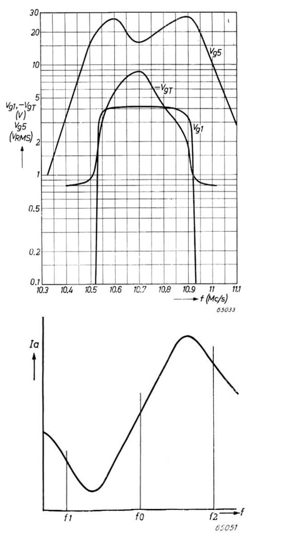
The problem that silent tuning solves is so called "False Locks" of the FM detector, see the bottom graph on the right. Normally the detector curve should be centred around the central IF of 10,7MHz (f0 in the graph), giving the broadest detection curve such that the received FM signal falls within the (almost) linear section of the detector curve. However, due to sine-like character of the detection curve, at frequencies f1 and f2 detection will also happen, albeit with a less optimal performance: the linear area is shorter and distortion will thus happen earlier, while the signal will be at the edge of the IF passband and will thus be attenuated more strongly, giving weaker output signals with a worse SNR.
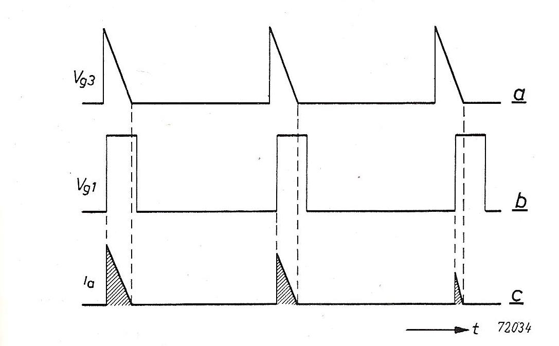
The Silent Detector is essentially a mechanism to detect whether the received signal is centred around f0. To this end the IF signal is tapped off before the EQ80 detector, passed through a narrow filter around fo (10,7MHz) and peak detected by one of the EBF80 detectors. (This is why the EAF42 in the Dammers-Hooijmans design has been replaced by an EBF80 in all the new concepts.) This detected signal can be seen as a narrow-band gain indicator, and is used to drive the EM34 tuning indicator gate. The anode output of the EM34 is used to derive a gating signal for Grid1 of the EQ80, see the upper graph curve Vg1. This signal is only high if the signal frequency is 10,7+/-0,2MHz, and only switches on the EQ80 in this mode. In all other conditions Vg1 is 0V, and in combination with the cathode voltage of +4V cuts off the entire valve. As a result of the Silent Tuning mechanism f1 and f2, the potential false lock points, fall outside the G1 gating window and can thus not be detected. |
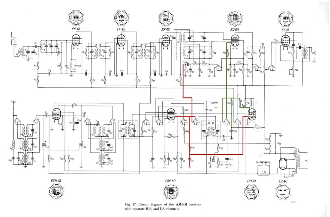
Circuit diagram of concept I for an AM/FM radio receiver with Silent Tuning. Red lines indicate the signal path of the narrow band detector centred around 10,7MHz, using the right detector of the EBF80. This signal controls the grid of the EM34 tuning indicator and becomes more negative in case of sufficient signal. In green the resulting bias voltage for the control grid of the EQ80, which is 0V in case of no signal and up to 4V in case of maximum signal. [Philips Electron Valves Division booklet "Receiving Tubes for FM" 11-1950]
|
Despite the extensive application support through the above booklet, practical use of the EQ80 in (FM) radios seems to have been rather limited. This is partly because actual FM radio transmission started late in countries like The Netherlands (1954) by which time the EQ80 had been replaced by cheaper solutions (see next). Italy is a country were FM was apparently introduced as one of the first, since from 1951 especially Magnadyne Radio (Torino) introduces a series of AM/FM radios FM3 to FM9, later followed by FM304-309. The actual design was not based on a known Philips reference design and used a mix of legacy and modern valves instead. But in all models the FM detector used the EQ80 according the Philips reference application design.
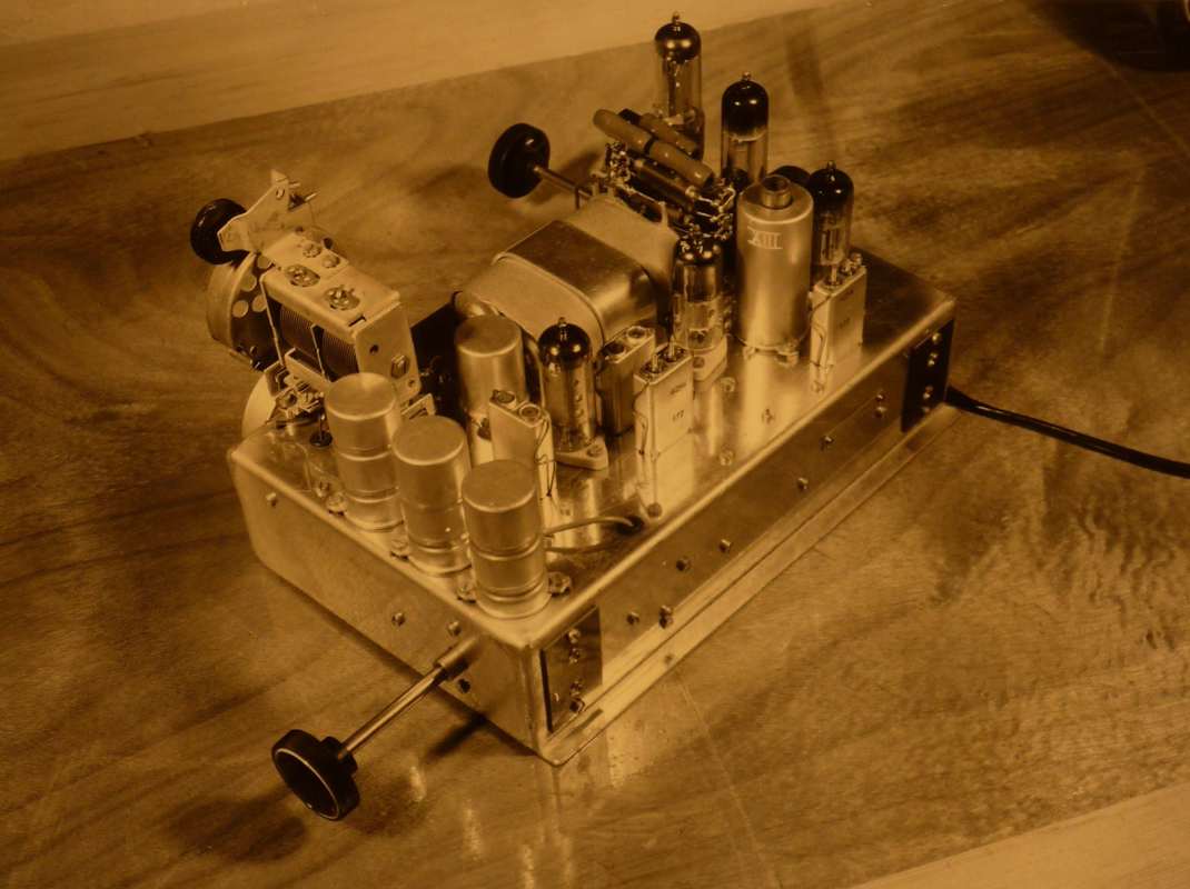
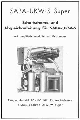
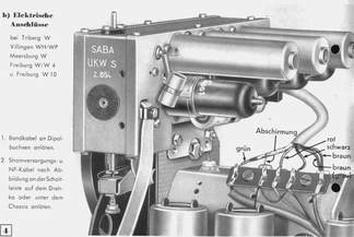
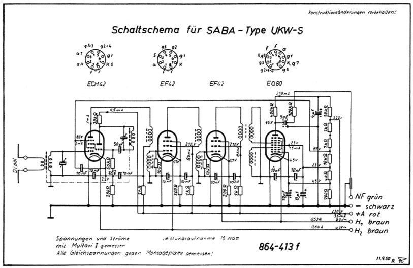
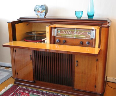
Another, and in fact almost the only, major user was the German company Saba (Schwarzwälder Apparate-Bau-Anstalt in Triberg), which brought out a series of luxury AM/FM radio sets called Freiburg, Meersburg and Villingen in 1951-52. These were original AM-only chassis with an additional so-called "UKW-S Einsatz" module taking care of the full FM sound reception. Physically it was a metal box with four valves, an ECH42, two EF42's and the EQ80. This looks suspiciously like the last Philips FM reference design of the FM chain, so I assume this was based on the Philips/Valvo solution. In 1952/53 Saba came with a last chassis containing the EQ80, the Konstanz. On this one the FM chain was identical but integrated on the main chassis. A last one worth mentioning is the Siemens SH705W "Gross-Super", a high-end AM/FM radio set. Interestingly this seems to be based almost 1:1 on the above Philips reference design for shared AM/FM valve use. It used the ECH42 and EF42 for the RF/IF, an EAF42 IF amplifier, EQ80 FM-detector, EM4 tuning indicator and EL41 end stage. So far it looks that this was the only Siemens set using this architecture apart from an Italian-built Siemens set coded S841. In this one the FM detection using the EQ80 and AM-detection using the EBL41 were split. Details on all sets using the EQ80 can again be found at Radiomuseum. On the right three pages from the SABA Service Upgrade Manual for installing the UKW-S Super FM upgrade module. [Radiomuseum.org] |
|
The only application I found of EQ80 use in radio FM detection by Philips was again a high-end platform: the FX700 and FX800 radio-record player combi's. The FX723A was the first in 1952, followed the same year by the FX824, which was also produced in the US under the Norelco brand. The ultimate model was the FX840 (also built in Italy as FI840), which was a combined AM (seven bands! 4 short wave, 2 medium wave and 1 long wave) and FM radio, record player and tape recorder. The FI850, again a dual mode radio-record player introduced in 1955, might well have been the last commercially launched consumer set using the EQ80. This supports the assumption that for radio the EQ80 was only affordable in the high-end segment, where cost pressure was lower. Because indeed these sets were really for the high end of the market, with sales prices of 1500 (for the FX824) to 2200Hfl (for the FX840), in today's money the price of a small car!
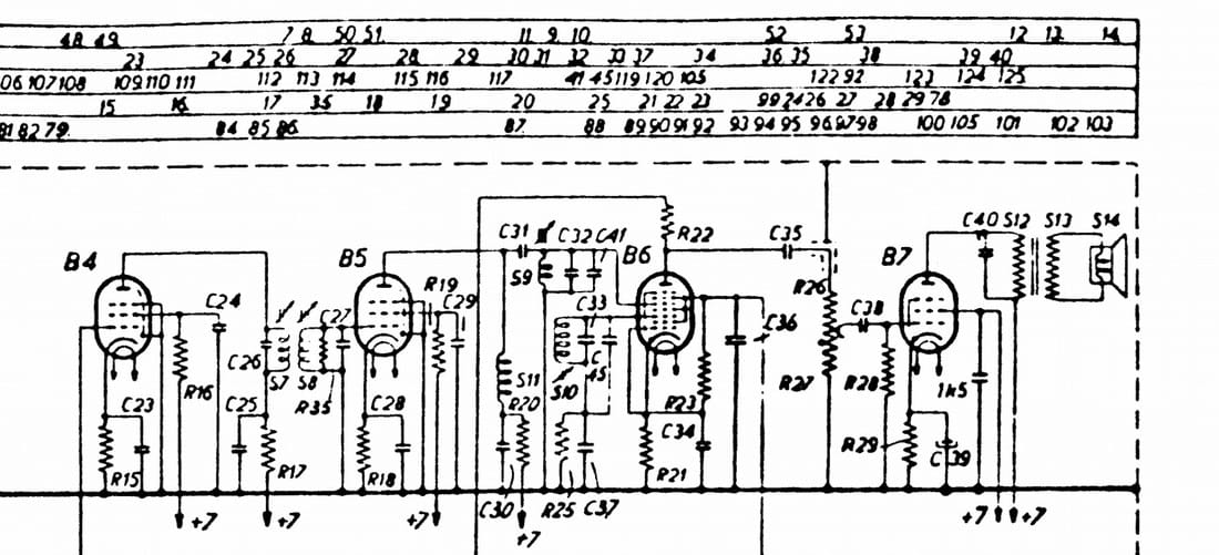
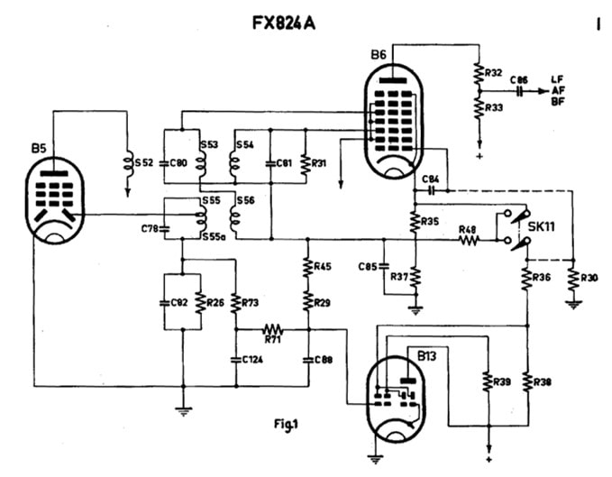
Interestingly the Silent Tuning concept as introduced in the reference design booklet of the Elektronenbuizen division was also used in the FX-family, albeit in a slightly adapted form, see the circuit diagram on the left. The 10,7MHz high-Q filter is now galvanically isolated from the primary filter section for the FM detector and directly fed into the detector diode of B5. But apart from some biasing the Silent Tuning control of the EQ80 g1 through the EM834 tuning indicator is roughly identical. With switch SK11 the Silent Tuning can be switched off, in which case g1 is directly connected to the cathode of the EQ80. So this seems like another (Dammers-inspired?) Radiobuizenlab concept applied in practice by the Apparaten division. The fact that the EQ80 was only used in the new and expensive television and FM-radio applications, for not more than four years (roughly 1951-1954), and in a period that most European economies were struggling out of the post-war recession, makes that the number of EQ80's actually used in these sets must have been limited. My guess is some tens of thousands in total. |
The EQ80 replaced
|
The mere fact that Piet Hooijmans was working hard on the applications of the EQ80 was unfortunately not enough to guarantee its broad use. In retrospect one can probably say that within the scope of valves it was one integration step too far. The same still happens today in IC integration, where there is for each function (or set of functions) an economic limit for profitable functional integration. Sometimes it is technically possible to integrate more, but the integral cost will be higher and/or customers are not willing to pay the associated price. It looks the same happened with the EQ80. The FM-detection function can also be performed with cheaper valves, and for dual mode AM/FM receivers the EQ80 made things unacceptably complex. Unfortunately, especially radios had to be dual mode and provided the highest volumes, so this was a major blocker for using the EQ80.
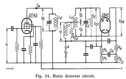
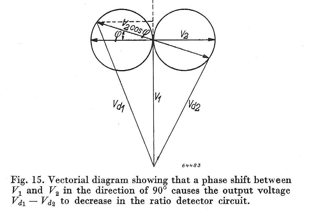
Consequently work started quickly on integrally cheaper detection architectures. The comparison table in the section "The EQ40 phi-detector" above shows that after the EQ40, the ratio detector comes out second best. The Ratio Detector concept is shown in Fig.14. Essentially it is a modified Foster-Seeley, where the two diodes also perform the amplitude limiting action. The voltage at the top of the secondary coil Ls is detected by diode 1, which as a voltage between anode and cathode Vd1, and the output current flows through R1. Similarly, the bottom voltage of Ls is detected by diode 2, with voltage Vd2, and flows through R2. Because from DC perspective the two diodes are in series, and the current through both will thus always settle to be identical. At point A, the LF output, the difference voltage (Vd1/Vd2)/2 is thus measured, which shows (along the circle) an amplitude relative to the input instantaneous phase (or frequency) deviation from the centre frequency. |
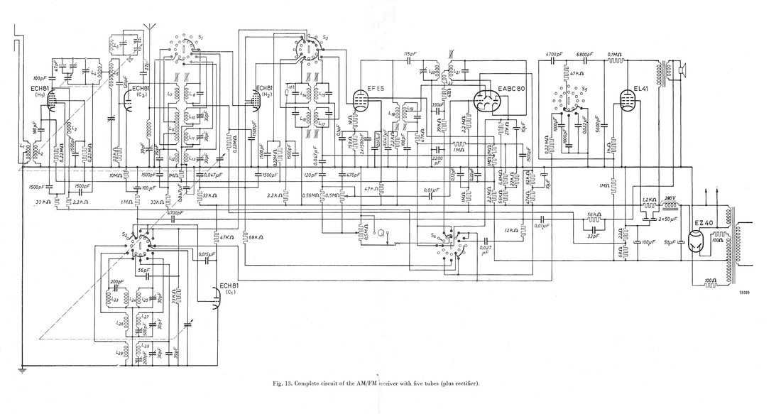
As it seems the ratio detector was chosen by Philips to become the standard frequency discriminator. This settled the FM detection, requiring a EB41 high transconductance dual diode, much cheaper than the EQ40 enneode. However, the AM peak detection still required a solution. This was solved by using a third diode, available in the EABC80 diode (A) dual diode (B) triode (C) combi valve. The separate diode (A) with a floating (non-grounded) cathode was used for one of the ratio detector branches, the two grounded dual diodes for the second ratio detector branch and the AM peak detector. Because both detectors have a much lower conversion gain than the EQ80, the triode was used as additional LF audio amplifier, boosting the input signal for the EL41 power amplifier. Below is the circuit diagram of a reference AM/FM receiver, as presented in the Electronic Application Bulletin article "New trends in AM/FM receiver design" by van Abbe, Dammers, Haantjes and Uijtjens, from December 1951. It contains the ratio detector and EABC80 application as discussed above. It is also noteworthy that the RF section has again changed compared to the previous one from 1949. The front end is now made with two ECH81 triode-heptode combi valves. The FM chain first uses the heptode as pre-amplifier, while the triode of the second ECH81 acts as mixer and down-converter. The triode section of the first ECH81 is used as oscillator for the AM bands, while the heptode takes care of AM mixing. In FM mode the second heptode acts as IF amplifier. With an EF85 IF amplifier and the EABC80 and EL41 this makes a five-valve full AM/FM line-up, even one valve less than the number unsuccessfully targeted in 1948 by Dammers and Hooijmans. This was essentially achieved by repartitioning the tube functions, a trend already hinted at by Dammers and Hooijmans in their 1949 report. As a consequence, the EQ80, once triumphantly introduced by Philips as the best solution for FM detection, unfortunately lost its place.
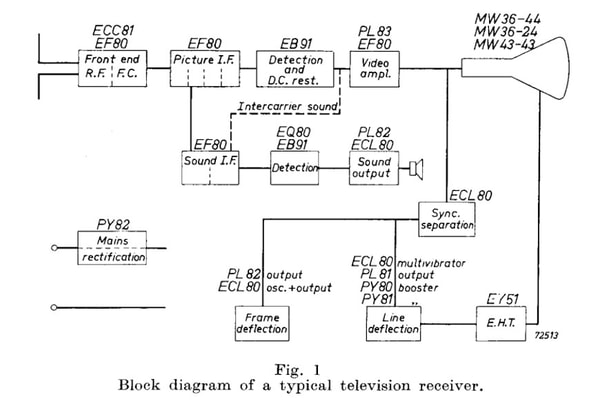
For television reception the trend was of course identical, although it took a different path. In the reference book on Philips Electronic Valve technology by J. Jager from 1953 "Part IIIC Data and Circuits on Television Receiving Valves" the below reference block diagram is given, showing for the sound FM detector both the EQ80 but also the EB91 dual diode. On the FM detection the book says:
Sound detection
For this application the special F.M. detector and limiter valve, Type EQ80, is available. In other detector systems, operating
with a double diode, the EB91 may be used.
This already suggest the introduction of and conversion to the ratio detector, as happened in radio. However, in contrast to the AM-FM radio were the EABC80/UABC80 combined AM and FM detector was used for many years, television quickly made the move to semiconductor diodes. Ratio detectors with two OA81 germanium diodes were introduced in 1954, thus eliminating valve-based FM detection.
A very last EQ80 design
|
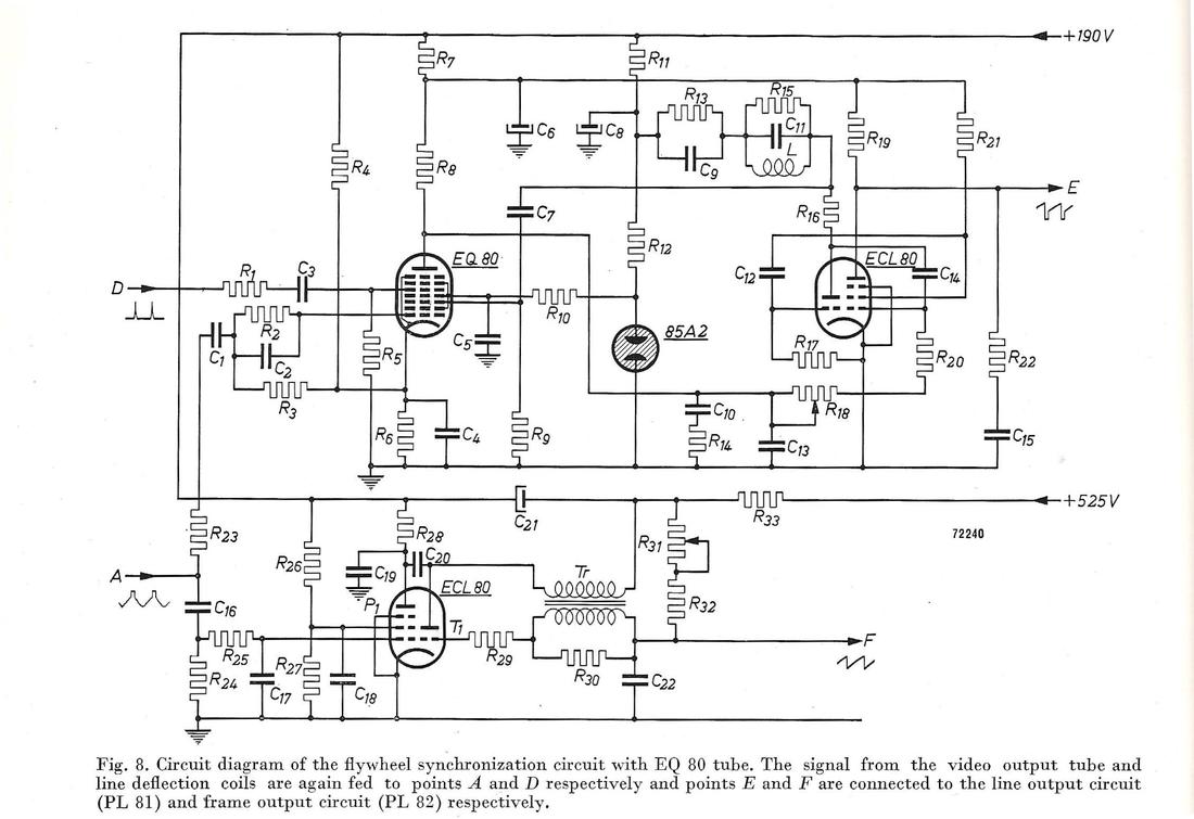
While the EQ80 was steadily pushed out of its FM detector role, all of a sudden a new application popped-up. Descriptions can be found in EAB 1953 No.3 pp.72-80 "Application of the ECL80 and EQ80 tubes for flywheel synchronization circuits" and in the mentioned Philips Electronic Valves part IIIC pp.171-176. As the title mentions, the EQ80 is used to synchronize the multi-vibrator for the vertical deflection with the synchronization pulses and the line frequency of the received video signal. In this application not two, as in the FM detector, but three control voltages are applied to the valve. The clipped video signal is applied to g1 in such a way that only the synchronization pulses will drive g1 to a negative voltage, allowing anode current. The oscillator output is applied to g3, while the flyback pulses are applied to g5. Now only when g1 and g3 and g5 are positive an anode current flows, where the amplitude is dependent upon the amount of overlap of the pulses. With a negative feedback loop the anode current can thus be used to control the multi-vibrator frequency to be identical to the line frequency of the received signal.
|
|
Although this application also clearly shows the capabilities of the EQ80 as coincidence phase detector, the problem probably remained as it was for FM detection: technically a perfect solution, but too expensive, and also achievable with cheaper valves.
I haven't found a single TV set using this concept, and I assume that it was never implemented in an actual television receiver. As such it can be considered as the last effort to push the application of this valve, although without a positive result. It marks the end of the EQ80 in commercial receiver applications. |
Still, the world is full of surprises! Because when I obtained a copy of the 1953 Volume IIIC "Data and Circuits of Television Receiver Valves" of the Philips Electronic Valves series, by the RBL engineer J. Jager, it not only covers the EQ80 application extensively, including the coincidence detector above. But at the end of the volume is a reference 625 line television receiver that contains two EQ80's; one as FM detector and one as coincidence detector for the line time base oscillator! In line with the method used in my story on the history of television development by Philips, I will call this design RBL6. It was linked to the TX1410 platform and especially TD1420 set from 1952. It clearly shows how much the Radiobuizen Lab continued to push their pet EQ80, up to the last moment when the valve was replaced by the PABC80 (for FM) and the OA81 (as coincidence detector).
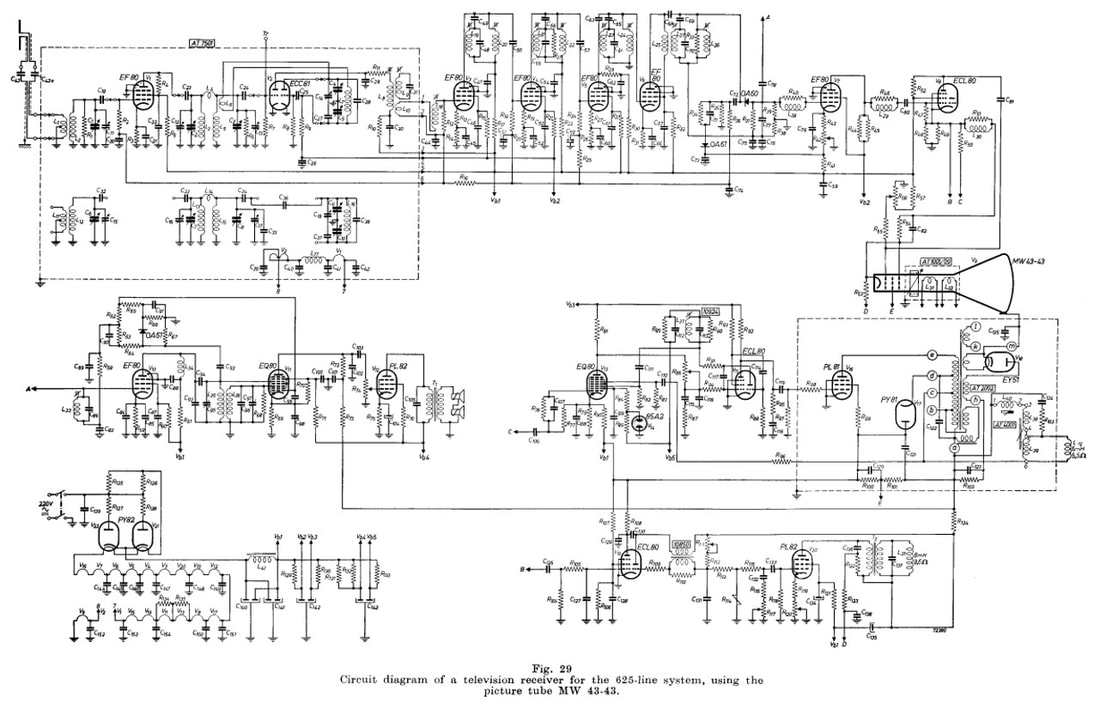
The reference design for a 625-line television receiver as published in Volume IIIC of the series Electronic Valves by the Philips Electron Tube Division (HIG Elektronenbuizen). This design clearly bears the signature of the Radiobuizen Lab, where the author J. Jager worked, and I therefore code it as RBL6. In the centre the two (!) EQ80's, the left one as FM demodulator, the right one as line time base oscillator coincidence detector. [Electronic Valves volume IIIC, J. Jager, 1953]
Other use of the EQ80
|
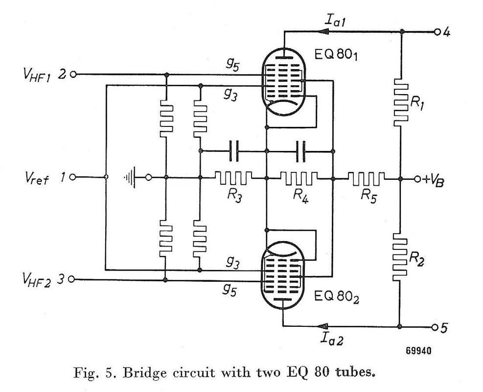
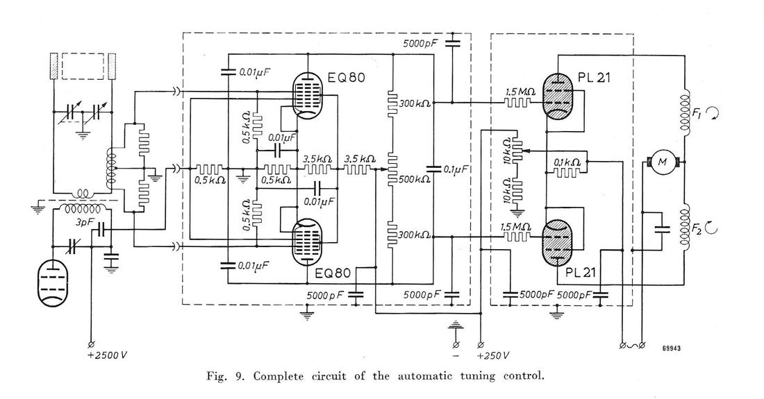
Apart from the consumer applications described above in detail, the EQ80 has undoubtedly also be used in professional applications. The problem is that these are much more difficult to find, so I will have to limit myself here to the single one described in the Philips Electronic Application Bulletin of January 1952 "Automatic tuning control of HF generators with variable load". The application is a 13,56 and 40,68MHz diathermy (RF heating) medical device with a capacitive dipole-like antenna. Because unknown loads (human bodily parts) will be positioned between the antenna poles the transmitter/generator will de-tune, severely reducing the heat transfer efficiency. The article describes a feedback and control loop using two EQ80 phase detectors in a balanced arrangement.
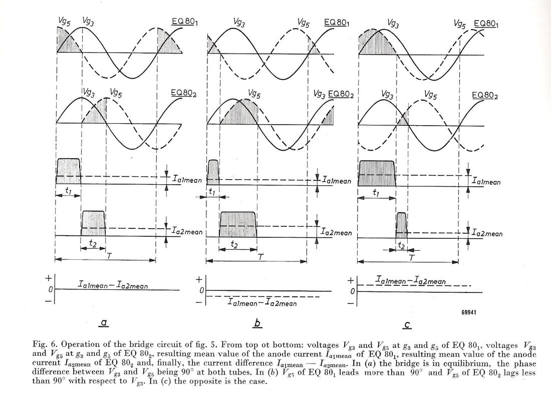
In Fig.5 we recognize the EQ80 phi-detector circuit, but now in a balanced arrangement. On both g3 grids the reference voltage Vref coming from the RF generator is applied. On both g5 grids the two HF voltages coming from the antenna pick-up coil are applied. The two voltages are needed because the control needs to work in both directions (positive or negative), depending upon capacitive or inductive antenna de-tuning. Fig.6 shows the principal voltages and the analogue AND-operation that the EQ80's perform. In case Vhf1 and Vhf2 are exactly in quadrature the two EQ80 output voltages have the same average (low pass filtered) DC-value. Deviations from 90degrees will make the one output higher and the other one lower. The full control circuit, using two PL21 gas-filled thyratrons, is shown below. |
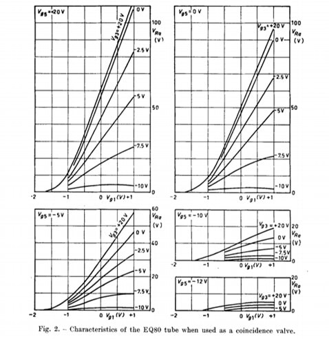
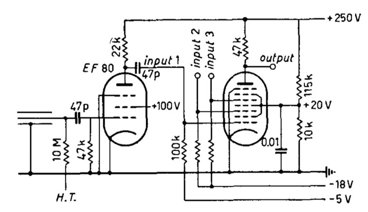
An entirely different application was discovered when Ite Weihe pointed me at the publication by E. Pohl of the University and the Instituto Nazionale di Fisica Nucleare (the National Institute of Nuclear Physics) both in Padova, Italy, titled "A simple threefold coincidence circuit using only one EQ80 (6BE7) valve". The application is Geiger counters in nuclear physics, where the desired positive output signal should only occur when three inputs are all simultaneously high. In the previous generation this was done with two-fold detection using an EF80, but three-fold detection with this valve was not possible due to the very high voltages required for cut-off. With the EQ80 this is possible, using g1, g3 and g5 as three independent inputs, each driven by an EF80 pre-amplifier. From the valve characteristics below it was determined that for complete cut-off the grids require the following voltages: Vg1=-2V, Vg3 = -12V and Vg5 = -15V. To be sure that no unwanted false triggers occur the actual grid bias voltages used are -5, -15 and -18V, respectively. When Vg1 is 1V and simultaneously Vg3 and Vg5 0V (all three from typical 5-6us Geiger tube pulses) this gives an anode output voltage pulse of 90V, see the upper right graph. Interestingly it is also remarked that the g3 and g5 triggers can be made for negative pulses, in which case the grid bias is made +20V.
All in all a very nice application that makes maximum use of the EQ80 capabilities. Based on the article I'm sure this design has been implemented within the Instituto's experimental measurement set-up.
All in all a very nice application that makes maximum use of the EQ80 capabilities. Based on the article I'm sure this design has been implemented within the Instituto's experimental measurement set-up.
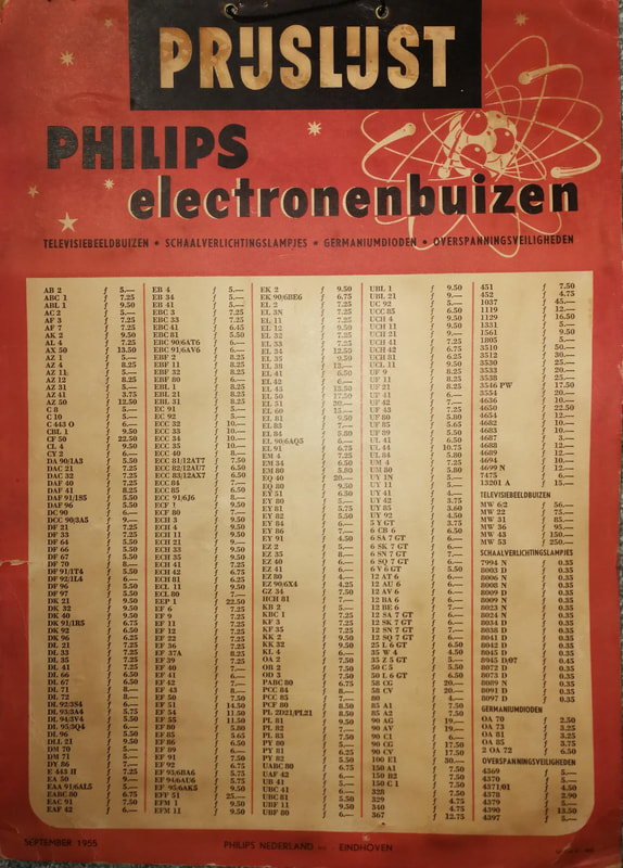
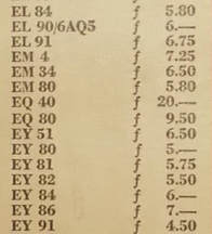
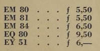
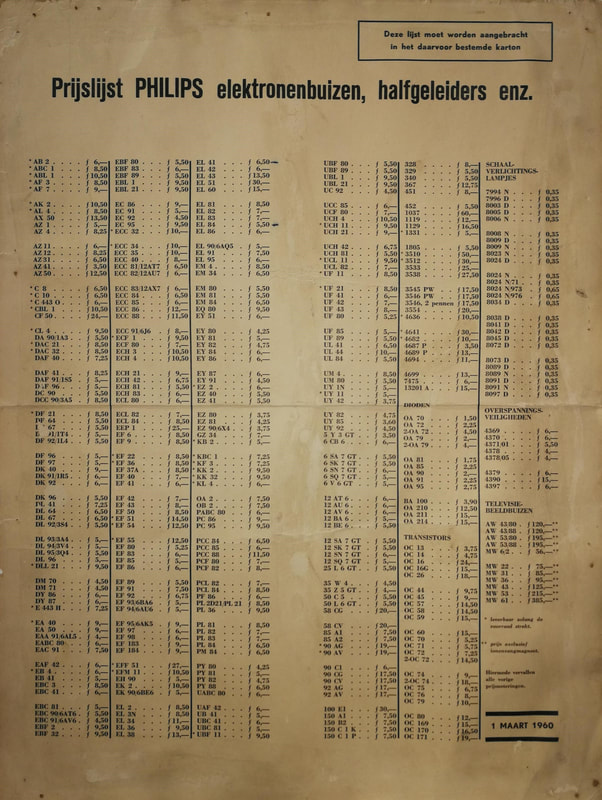
The above price lists are the last contemporary witnesses of the EQ40/EQ80 existence, and provide again some surprises. So despite the fact that the EQ40 was effectively not used in any commercially released Philips set, it was nevertheless still for sale in 1955! It is unclear whether these were earlier produced valves that were still on stock, or from running production. In 1960 the EQ80 was still for sale, seven years after its last known application, so this must primarily have been for service replacement of valves used in the first generation TX400, TX500 and TX1410 TV sets. Interestingly the price of the EQ80 had not changed in these 5 years, price erosion was apparently not as tough as it is today. Still Hfl 9,50 (Dutch guilders, so roughly 4,5USD) was a considerable price at the time, not to speak of the 20,00 Hfl for the EQ40!
EQ40/EQ80 closing remarks
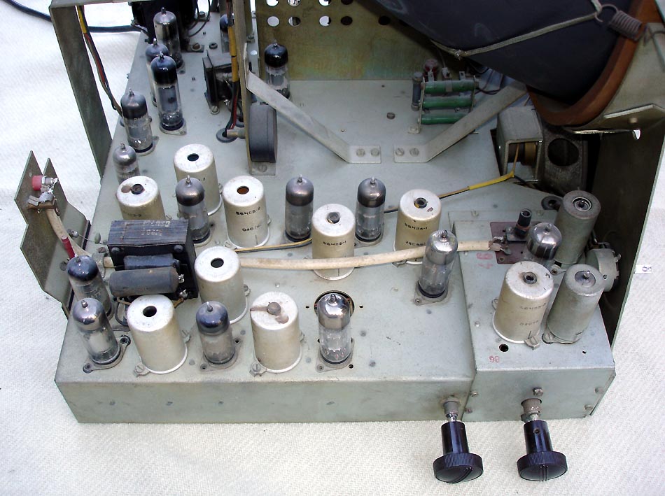
Forty years ago, when carefully looking inside my fathers old home-built TV receiver, I was always intrigued by the EQ40, especially when my father told me this was the only nine-electrode enneode valve ever developed. It therefore gives me enormous pleasure to have written this - very personal - history on the EQ80, which turned out to be so much more interesting than I had anticipated. I had never realized that the EQ80 was so intimately linked to the first television and FM radio receivers, and that it is thus part of a very exciting period in the development of consumer electronic devices we take for granted today. This was made all the more interesting - at least to me - by the fact that my father in his younger days was part of these developments, it gives me an enormous sense of pride. Since my father never threw away anything of interest, I'm happy to possess the reports from his days at Philips Radiobuizenlab as well as the EAB journals, which were an invaluable source of information when writing this story.
As with every historical investigations the writer is forced to some level of interpretation; one doesn't have access to all data, and the story is therefore never complete nor perfect. The same will be true for my EQ40/EQ80 history. Anybody with additional information or comments is invited to contact me.
January 2017
No information nor most of the pictures on this site are copy-righted, and can thus be used freely. However, if text, drawings and drawings modified by me are used, it is appreciated if a reference to my site is included.
References
- Philips Radiobuizen Lab I Report Q-46S-II, Beschrijving van een A.M./F.M. ontvanger (Description of an AM/FM receiver), B.G. Dammers, P.J. Hooymans, March 5, 1949.
- "The phi-detector, a new valve for FM receivers", J.L.H. Jonker and A.J.W.M. van Overbeek, Philips Electronic Application Bulletin (EAB), Vol.X, Nr.5, pp.109-117, April 1949.
- The phi-detector, a detector valve for frequency demodulation", J.L.H. Jonker and A.J.W.M. van Overbeek, Philips Technical Review, Vol.11, Nr.1, pp.1-32, July 1949.
- "F.M. detector circuits", C.J. Boers, Philips Electronic Application Bulletin (EAB), Vol.11, Nr.10, pp.181-199, October 1950.
- "EF42, EF43, EQ80, EB41 Receiving tubes for FM", Philips Electron Tube Division application booklet, November 1950.
- "New trends in AM/FM receiver design" by van H.H. Abbe, B.G. Dammers, J. Haantjes and A.G.W. Uijtjens, Philips Electronic Application Bulletin (EAB), Vol.12, Nr.12, pp.209-226, December 1951.
- "Automatic tuning control of HF generators with variable load", H. Hertwig, Philips Electronic Application Bulletin, Vol.13, Nr.1, pp.9-18, January 1952.
- "Application of the ECL80 and EQ80 tubes for flywheel synchronization circuits", A. Boekhorst, P.D. van der Knaap, P.A. Neeteson, Philips Electronic Application Bulletin (EAB), Vol.13, No.5 pp.72-80, 1953.
- "Philips Electronic Valve technology - Part IIIC Data and Circuits on Television Receiving Valves", J. Jager, 1953.
- "A simple threefold coincidence circuit using only one EQ80 (6BE7) valve", E. Pohl, Il Nuovo Cimento, Vol.3, No.3, pp.642-644, March 1956.
- Radiomuseum.org for service documentation of all TV and radio models mentioned on this page.
- Frank pocnet for the Philips service documentation of the TV sets mentioned on this page.
Updates
July 2017
- added the Radiobuizen Lab RBL6 reference design that I discovered in Volume IIIC of the Philips Electronic Valves series.
- have added chapter navigation and links to my other pages on television history for better cross-referencing
- have added the pictures of the price lists
- added radio application info based on the booklet on new Philips valves for FM Radio that I got from Oswald Moonen, including Silent Tuning function and reference design.
- added pictures of the SABA FM module with the EQ80.
- added story on the Italian nuclear physics institute on a threefold EQ80 coincidence detector, which was found by Ite Weide.
- added References section
