|
The entire content of this web page, plus much more, can be found in the book shown left, the first part of the Philips Technology History series.
For details and ordering information please see the dedicated page ordering my books. |
Introduction
|
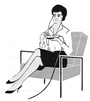
With the emergence of Television, and especially when multiple TV channels came available towards the end of the 1950s, remote control (RC) became an important desired feature. People did not want to get our of their chair to change channels or volume! In 1955 Philips introduced wired remote control. A simple handheld console, connected to the TV set through a 4-wire cable, allowed brightness, contrast and speaker volume setting of the TV. From then on most Philips chassis offered the technical option of wired remote control, with increasing functionality. It seems that especially in Germany, with a larger high-end market for Philips, the use of RC was more widespread than in e.g. the Netherlands, where people were less willing to pay for such luxury.
|
Page navigation
|
The reason for covering remote controls here is the fact that the first generations wireless (ultra-sonic) remote control were developed in the same Edens-lab as the tuners. Although the frequencies were not comparable, they were apparently seen as RF products. Furthermore, some form of tuner control was considered the ultimate feature of the wired remote control. And the strongest driver for ultrasound RC technology was the need to support the increasing number of TV channels. And finally these early remote controls are interesting given the innovative new technology of ultra-sound, while also the first digital ICs were used. Ultra-sonic remote control technology did not live for long, however, quickly to be replaced by infra red. But ultra-sonic paved the way for wireless RC!
To make the bridge to the technology it replaced, I'll start with briefly describing the earlier generations of wired remote control. And finally, while diving into the remote control developments, it was logical to cover the first generations infrared RC too. Especially because it took some effort to find out how the first generation RC4 was designed. So, in the end it became a story about the first 30 years of television remote control, from 1955 to 1985.
To make the bridge to the technology it replaced, I'll start with briefly describing the earlier generations of wired remote control. And finally, while diving into the remote control developments, it was logical to cover the first generations infrared RC too. Especially because it took some effort to find out how the first generation RC4 was designed. So, in the end it became a story about the first 30 years of television remote control, from 1955 to 1985.
The first wired remote controls, 1955
As we will see the remote control seems to have been a German-centric development, although it can not be excluded it was not a parallel development with Eindhoven. However, so far I haven't found any data on simultaneous, Eindhoven developments. So the first formal trace of a remote control is for the 1953 TX1720 (sometimes referred to as C1)-platform. This comprised the Eindhoven TX1420 and TX1720, and the Krefeld versions TD1422, TD1720 (and 27 and 28) and in 1954/55 the 21TD100 family. At least all these German sets could be used in combination with remote control KR 357 54. (This coding referred to the same larger family of Krefeld-produced television modules, the VHF tuners being KR 361 xx).
|
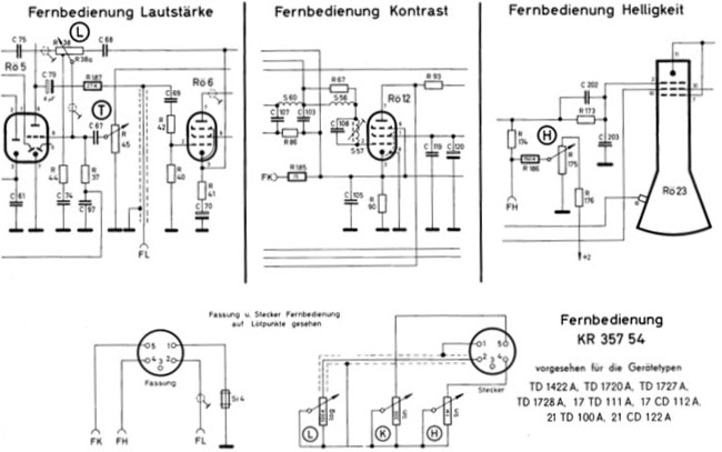
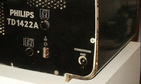
Exactly how and when this first remote control was introduced is still unclear, but it seems to have been a form of retro-fit or service solution. On the data sheets and the manuals of the set there are no remarks as to the use of a remote control. The connections are also not indicated on the circuit diagrams. Which suggests that the three connections for the controls were soldered onto the chassis. But then the strange thing is that on the back of for example TD1422 and TD1728 there was a switch labelled "Fernbedienung - Ohne Mit" (Remote Control - Inactive Active), which suggests the feature was installed during production. Alternatively, the set received a new back cover in case remote control was installed. But apparently, although one won't find it anywhere in a data sheet, on these earlier sets a remote control override switch was installed, which makes sense in case the wires are soldered to the chassis.
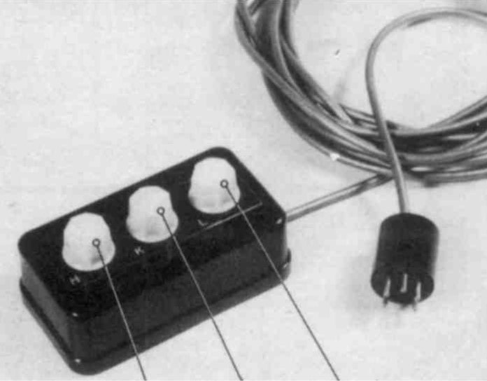
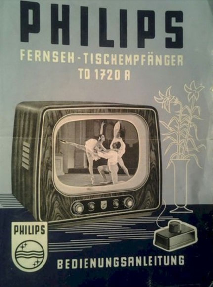
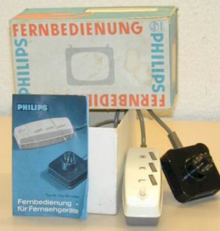
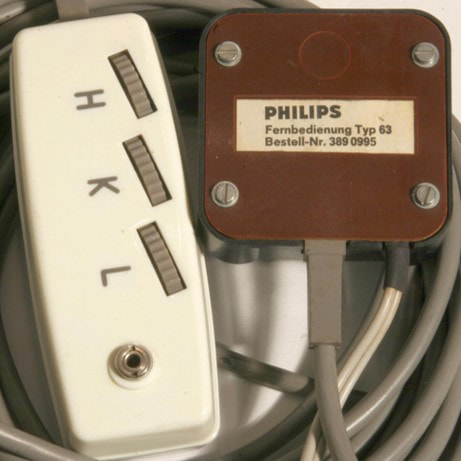
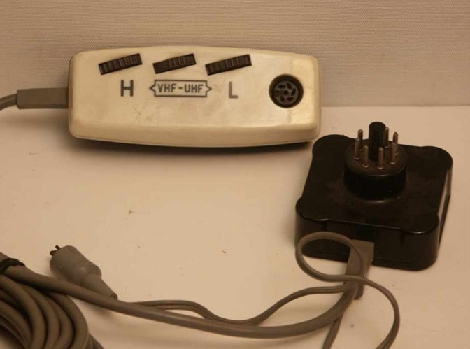
The functions of this first RC were three-fold: picture clarity, picture contrast and speaker volume control through three potmeters. The clarity control (FH)was directly parallel to the standard control potmeter of the set, thus reducing the overall resistance controlling the display tube g1 gate voltage. Contrast control (FK) changed the gain of the video power stage by reducing the cathode feedback resistor. And the volume control (FL) was set parallel the g1-bias of the sound power amplifier, controlling the Vgk of that valve. The controller, a small bakeliet box, was connected to the TV through a 6m-long 4-wire cable. A next unresolved issue is the TD1720A leaflet on the right, which shows a single-knob remote control unit. So far I haven't found any trace of this RC version, but I assume the control was for speaker volume only. Was this the KR 357 51 or 52???
For the 1955-1959 families the concept was continued, sometimes with slight variations of the potmeter values. But these new versions, KR 357 53 and 55, introduced a 5-pin plug, to be connected to female socket on the chassis. This eliminated the need for the on/off-switch discussed earlier. In this period all high-end sets from Krefeld - 21TD140 through to 21TD230 - were "remote control-ready". I have not found any traces of it, but it was of course perfectly possible to app;y the Krefeld solution to the Dutch chassis like the 21TX140 |
|
The AT6320 with galvanic isolation, 1958
|
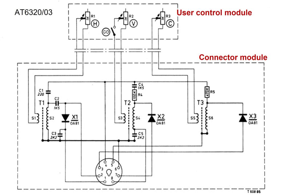
One of the main drawbacks of the first generation remote control was that the three potmeters in the control unit were directly connected to higher voltage nodes inside the TV set, thus generating potential risks in case the wires or control unit were damaged. There clearly was a need for galvanic isolation of the control unit from these high voltages, and this was the main innovation in the AT6320 remote control. As the name indicates, this was an Eindhoven development (AT were Eindhoven electronic TV modules; AT6321 was the first UHF tuner).
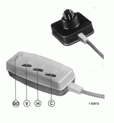
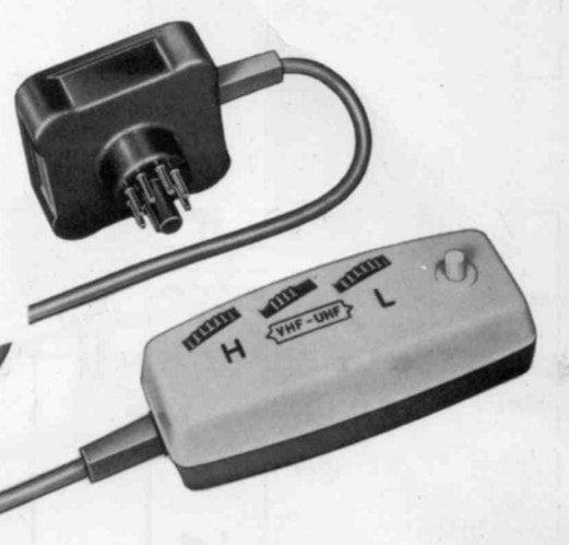
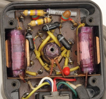
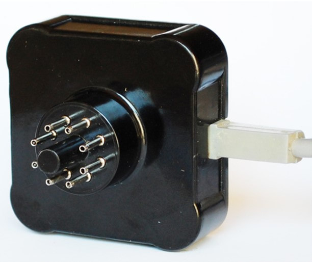
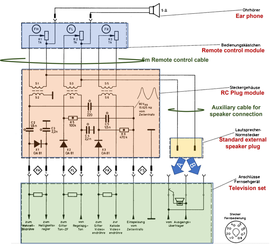
Apart from the galvanic isolation, the AT6320 introduced another few conceptual changes. The first was the introduction of a standard connector, which was similar to the PL36 valve octal base. This was to be the standard interface for all wired remote controls for the coming decade. Secondly, a small box integrated with this connector now contained most circuitry including the galvanic isolation transformers. Only three dual-wire lines connected to the - now low voltage - potmeters in the user control module. A dedicated power supply was provided from a tap on the line output transformer. Finally the AT6320 introduced the all-important mute function for the sound (GO for Geluidonderbreker). Until 1961 this 4-control RC was to be the standard remote control. |
As so often, there was not much alignment or co-ordination between the different TV development sites, and where Krefeld continued its first generation till 1959, Eindhoven introduced the AT6320 in 1957 with the 21TX180 family. Also here several small modification had to be applied with every new TV family, but in the end the standard version settled on the AT6320/03, which was from then on used. Here again the German and Dutch approach differed, since only the more expensive Krefeld sets were ready for RC. In Eindhoven, however, since from 1957 up to the 1964 23TX460 family all TV sets were standard ready for use of the AT6320. But then, in 1965, all use of wired remote control on Eindhoven sets was stopped, only to re-appear with the ultra-sonic controller.
|
Krefeld remote controls, differentiation, 1960-1967
|
Where Krefeld continued with the first generation until 1959, in the 1960 chassis they introduced the AT6320/03 concept called Type 60 Fernbedienung, with internal module code KR 357 58. Almost immediately the different approach between the central Eindhoven and German Krefeld approaches became evident: whereas Eindhoven offered the single AT6320/03 for all sets, the German marketing opted for differentiation. Throughout this period the basic remote control remained unchanged, and identical to the AT6320: clarity-contrast-volume control plus mute. I'll therefore focus on the functional modifications that were introduced.
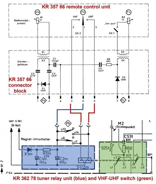
Parallel with the Type 60 already a Type 60 Luxus was offered, deleting the contrast control. The first real new function, however, was linked to the introduction of UHF reception in the early 1960s. The 1962 television product range offered the top models Leonardo Luxus AS (23TD361A and 362A plus equivalent models including a radio) with remote controlled VHF-UHF switching. To this end the VHF tuner was equipped with a relay for this band switching, mounted on top of the tuner. This was a so-called bi-stable relay, that only needed a short pulse to switched to either of its two stable conditions. One for VHF, one for UHF, see the tuner section on the AT7639 for details.. This relay could be operated by normal front panel push buttons, but now also by the remote control, Type 62 Luxus (KR 357 66). To safe space the contrast control was sacrificed, and replaced by the VHF-UHF switch. |
Although the VHF-UHF was not a cheap future (dedicated remote control version, the bi-stable relay and switch) this was probably acceptable for the high-end Leonardo sets, because this function continued to be available in the next two generations remote controls.
The 1963 range introduced yet another new feature: an ear phone that could be connected to the remote control unit. It replaced the Mute button |
|
The ear phone connection to the remote control unit was quite different from the clarity, contrast and volume controls. The contacts did not use the standard Octal remote control plug, but a separate 2-core wire coming out of the RC connector that ended in a separate standard external speaker male connector. This connector could be plugged in two ways: using the two left pins of the female connector (A in the drawing), thus disabling the main TV speaker such that sound only came to the remote control ear phone. When rotated 180 degrees and inserted in the two rightmost receptacles (B in the drawing) the ear phone was connected parallel to the main speaker and both would generate sound.
In parallel the general re-naming of the Krefeld television components had taken place, becoming NT11xx for the remote controls. Which seems a form of take-over of the Eindhoven AT coding for electronic modules. The first remote control in this system was the NT1162 Type 62 with the new ear phone feature. |
|
The approach continued one more year with the 1967 NT11774 and 1176 controls, offering the by now standard clarity and volume control and ear phone (NT1174) with optional VHF-UHF switch (NT1176). The only change was the external design, which became more rectangular and thinner. At the same time the NT1176F (for Farbe, colour) introduced the colour saturation control feature, replacing the VHF-UHF switch. The saturation control was still in the same way as used earlier for contrast, modifying the cathode feedback resistor of the EF184 burst amplifier in the new K6 colour chassis. With that, the first generations of wired remote controls ended, after its introduction in 1955.
12ET0850, the first multi-channel controller, 1968
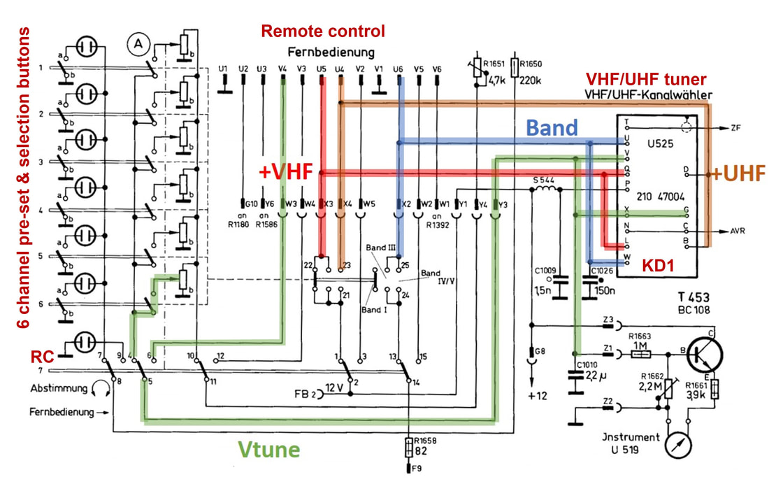
By this time some fundamental changes were taking place inside the TV, with considerable influence on the remote control concept too: the introduction of colour TV, the change over from valve-only to transistorised and even the first ICs, and finally varicap-controlled tuners. These new developments came together in the K6N chassis, the first colour television from the Krefeld factory. The D25K860 Goya Luxus Color Automatik used the new KD1 VHF-UHF tuner in combination with new front panel push buttons for pre-set and selection of six TV channels. Since the tuner was varicap tuned, pre-setting of a channel now involved much simpler operations: setting the band selection switch (VHF-I, III or UHF) and setting the tuning control potmeter. The concept of this TV front panel channel control was now copied on the new remote control for four channels.
|
|
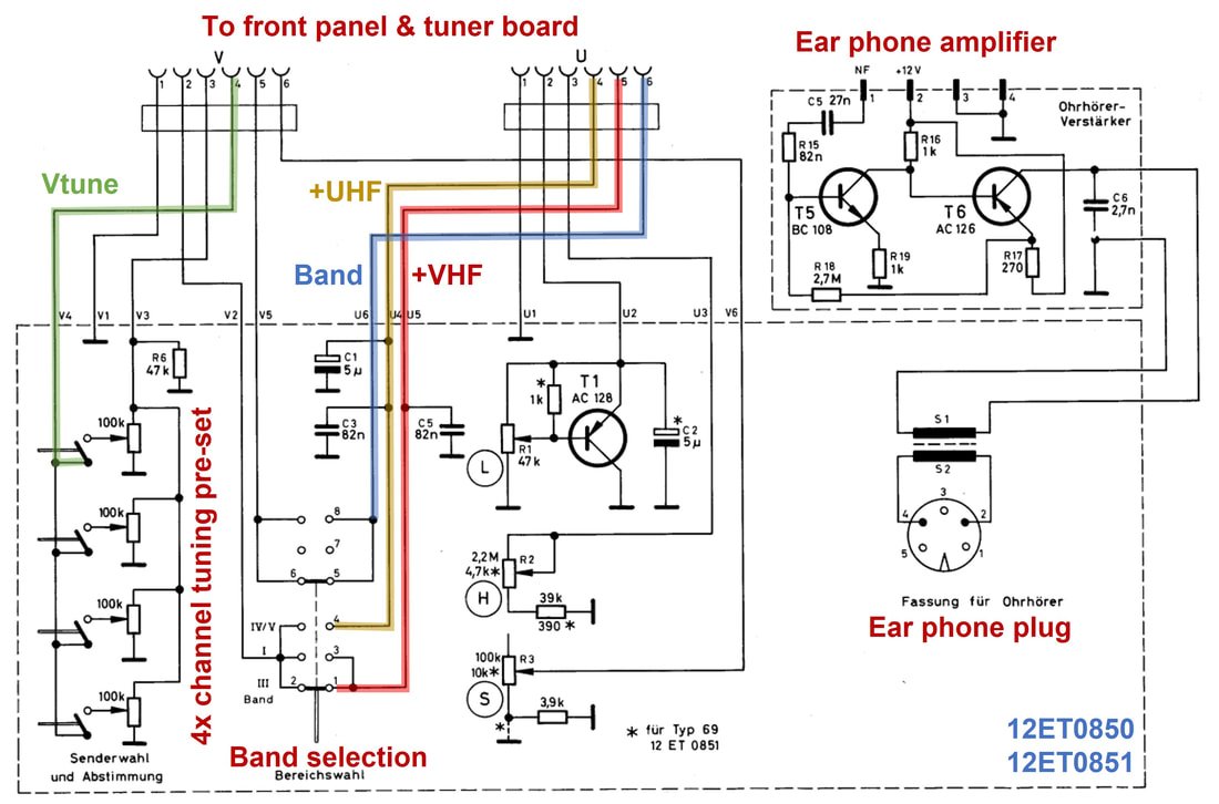
The remote control was sold as Type 68 Luxus, but internally coded as 12ET0850. The 12ETxxxx coding was yet another new system, 12 referring to Germany, ET to electronic TV modules. The KD1 tuner was for example coded as 12ET5630.
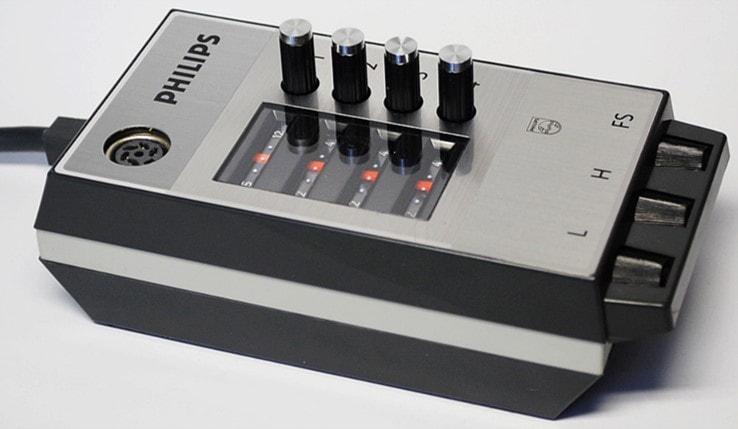
To allow remote control operation the front panel of the TV had below the 6 channel selection knobs a seventh to engage the remote control (see the lower diagram marked RC). Pressing this button essentially switched all power supply lines from the front panel to the remote control, which had identical circuitry, albeit with only four channels. The four buttons on the remote control could thus be used to pre-set the band and the channel tuning potmeters for four individual channels. Which did not have to be identical or in the same order as those set on the TV front panel. Each of the four channels had a separate tuning and band indicator, see the picture. Next to these new channel selection functions, the RC contained all three by now standard control functions clarity (H), volume (L) and colour saturation (S or FS). Note the single transistor buffer amplifier for the volume. The ear phone plug was connected to a small impedance transformer and a dedicated ear phone transistor amplifier on the chassis. All in all this remote control was clearly a complexity and feature step up compared to the previous generations, making use of the transistorization of the TV. At the same time it showed also the limitations related to these more complex control functions: the interface requirements became much more complex. The 12ET0850 used in total 14 interconnect wires for all functions, and increasing this much higher would certainly make the long cable prohibitively expensive. This increased the need for a truly wireless remote control, and the 12ET0850 would indeed be the last generation wired remote controls. |
RC1, the Philips ultra-sonic remote control, 1972
The reason for this sideline story is, as said, the fact that the next generation, truly wireless remote control, was developed in the Edens or Tuner Lab. Apparently ultrasonic was considered a form of RF, and the tuner group the best place to develop this. At the same time the total solution development was much bigger, especially the receiver was a - for the period - advanced digital sub-system, and was undoubtedly developed by a group inside the TV development lab. So I assume that the ultrasonic transmitter and receiver modules were developed in the Tuner -lab, and the digital receiver by TV, based on an integral TV architecture. In the Tuner -lab 3 persons worked on the transmitter and receiver, thus guaranteeing they properly worked together.
|
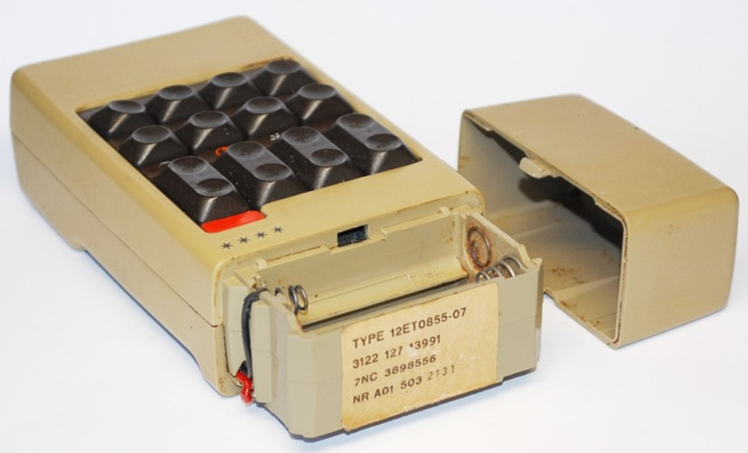
Ultra-sonic was the technology selected for these first wireless remote control, an RF link probably still too expensive. It is not clear of infrared was already an option that was discarded (if so, then almost certainly for too high cost) or only came up later. The frequency range selected was from 37 to 41kHz, so well above the human hearing capability. (Dogs might have heard the signals, though). The transmit and receive transducers were ultra-sonic "speaker" and "microphone", which seems to have been the same bi-directional device, given the identical service 12nc. So far it is not clear what the product coding and origin of these transducers was.
|
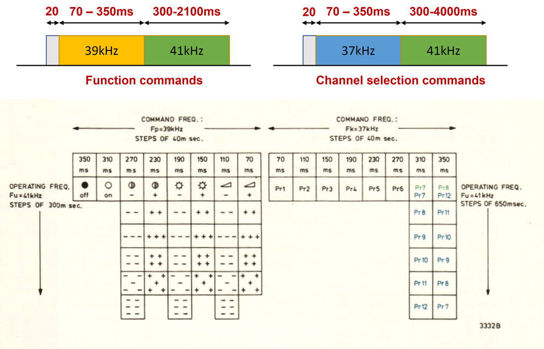
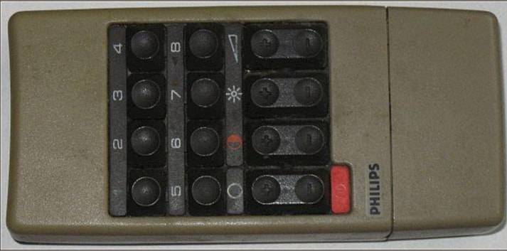
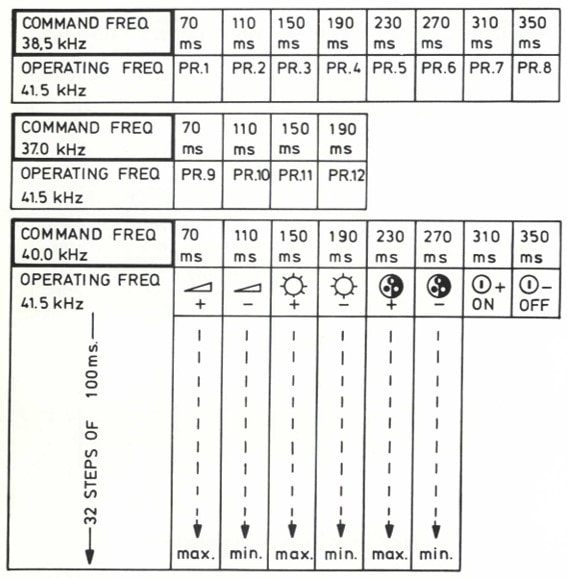
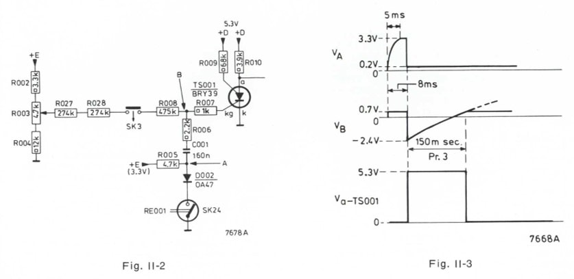
The transmission protocol was based on analogue transmission, with time and frequency modulation, see the diagram. There were two groups of buttons on the remote control unit, Group 1 (SK1 to SK8) controlling the functions on/off, sound volume up/down, clarity up/down and contrast up/down. Group 2 (SK9 to SK16) controlled program selection, where the first six buttons were for fixed programs PR1 to PR6, and the last two for up-down stepping to programs PR7 to PR12 upwards and PR12-PR7 downwards. Which of the buttons inside a group was selected was transmitted through a frequency of variable length. For Group1 this frequency was 39kHz, for Group2 37kHz. The lowest button (SK1 and SK8) gave a 70ms frequency burst, any next higher button added 40ms each time. So, the first burst indicated the Group (frequency 39 or 37kHz) and the button within that group (70-350ms length). Immediately after this first frequency burst the transmitter switched to its highest frequency at 41kHz, which remained active as long as the button remained pushed-in by the user. For most of the buttons (e.g. volume, clarity, contrast) the duration of the 41kHz burst indicated how many steps of up or down change had to be applied.
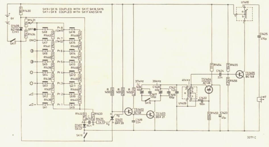
The way this was implemented is shown in the circuit diagram above. When a function button was pushed (to start one in Group1, SK1-SK8) any button would also activate SK17, which connected the battery. The individual button effectively selected a point in a resistor ladder network, by-passing the higher resistors. As soon as the battery power was connected thyristor D1401 started to conduct, grounding the base of transistor TS1402. Through some mechanical construction, SK18 at the bottom of the circuit was closed 20ms later, abruptly cutting off the thyristor, raising the base voltage of TS1402 and thus switching on both TS1402 and TS1403. This in turn switched capacitors C1420 and C1421 parallel to the oscillator tank circuit formed around transformer U1409 and transistor TS1404, which had a natural oscillating frequency of 41kHz. But the additional capacitors now reduce the frequency to 39kHz, which is amplified by TS1405 and then transmitted by transducer MT. In parallel, through the integral ladder network resistors, C1415 in the gate circuit of the thyristor was charging, determined by the integral time constant of the RC-circuit. If for example SK3 was selected, the RC-time would be 150ms before the voltage on the thyristor gate would reach 0,7V again switch the thyristor back on. This switched off TS1402 and 1403, de-activating the parallel capacitors and switching the oscillator to its natural 41kHz frequency. This would last as long as the button remained active.
Activating a program button from Group2 (SK9-SK16) worked completely along the same lines, apart from SK19 also being activated, which switched additional capacitors to the oscillator tank to further reduce the frequency to 37kHz.
Activating a program button from Group2 (SK9-SK16) worked completely along the same lines, apart from SK19 also being activated, which switched additional capacitors to the oscillator tank to further reduce the frequency to 37kHz.
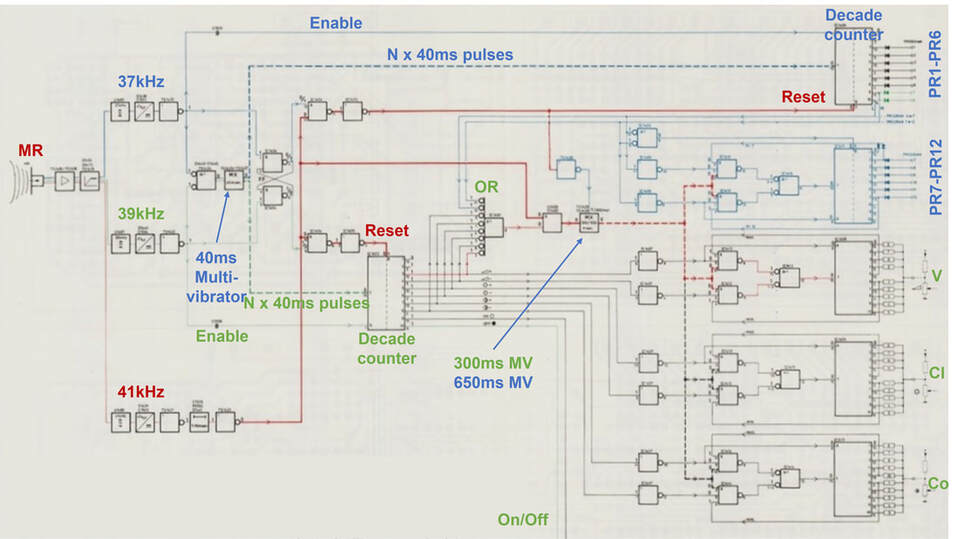
The receiver will only treated on a higher level, being essentially a digital processor using the first standard TTL logic ICs. The front end of the receiver used the same ultra-sonic transducer, followed by a pre-amplifier and a limiter. The signal was then split into three branches, each centred around a band pass filter (BPF) on the three transmitter frequencies (37, 39 and 41kHz). If we first look at a function command transmission (e.g. clarity up, SK3), the receiver will first receive a 150ms burst at 39kHz. After rectification and pulse restoration this results in a digital pulse of 150ms at the output of the 39kHz branch. This pulse is used in two ways. First it acts as the Enable signal for the green decade counter. Secondly, the pulse will activate an a-stable multi-vibrator that generates short pulses with a repeat time of 40ms. In this example (the 150ms pulse) pulses will be triggered four times, at 0, 40, 80, and 120ms. These four pulses advance the decimal counter 4 positions such that output 5 is activated (high). At this point the 39kHz pulse ends, and is replaced by the 41kHz signal, which is detected by the red branch, and generates a pulse as long as the remote control button is activated. The output 5 of the decimal counter is one of the inputs to an OR-gate, that is connected to all outputs where the length of the 41kHz pulse determines the amount of change. The output of this OR and the 41kHz pulse open an AND-gate, and if so activate a similar multi-vibrator, but this time generating 300ms interval pulses. The decimal counter output acts as Enable UP and the multi-vibrator output as activator of an up-down counter. Pushing the Clarity Down button will likewise activate output 6 which acts as Enable DOWN for the counter. The counter outputs are combined using a resistor ladder network to form an analogue output voltage for the function Clarity (Cl). Volume and contrast work in exactly the same way, the On and Off switched don't require the Up/Down functionality and go directly to the TV set power supply Stand-By controller. When the remote control button is released the 41kHz burst stops, and the trailing edge of the pulse in the receiver is used to reset the decade counter to 1.
|
|
Pushing one of the Group2 program selection buttons generates a 37kHz pulse, which is received by the 37kHz branch, and operates yet another decimal counter. This operation re-uses the 40ms multi-vibrator. A special operation starts when PR7 or PR8 are pushed, which allow stepping through the channels 7-12 (Up) or 12-7 (down). These outputs are also connected to the OR-gate, but the second multi-vibrator is now switched to 650ms interval pulses, to allow settling of the tuner to the channel with each step. This is the blue circuitry in the block diagram.
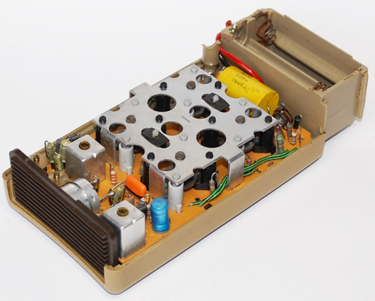
The receiver used the first generations ICs made by Philips. The standard logic functions used the FJH-family TTL ICs from Southampton: the FJH101 octal-OR, FJH121 (Flip-flop plus OR), and FJH241 (six inverters). The decade counters used the TCA810 bipolar IC. All other functions were still made from discrete BC548 transistors, including the multi-vibrators. All electronic circuitry was still implemented as wired components on single-sided PCB boards, requiring quite some space. The handheld module, requiring four 1,5V batteries to provide 6V supply voltage, was therefore still a fairly bulky device compared to today's remote controls. But it was wireless! The receiver was mounted on a single dual-layer PCB board, and roughly 25cm long. |
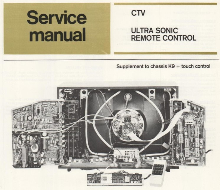
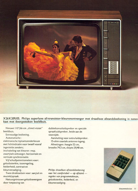
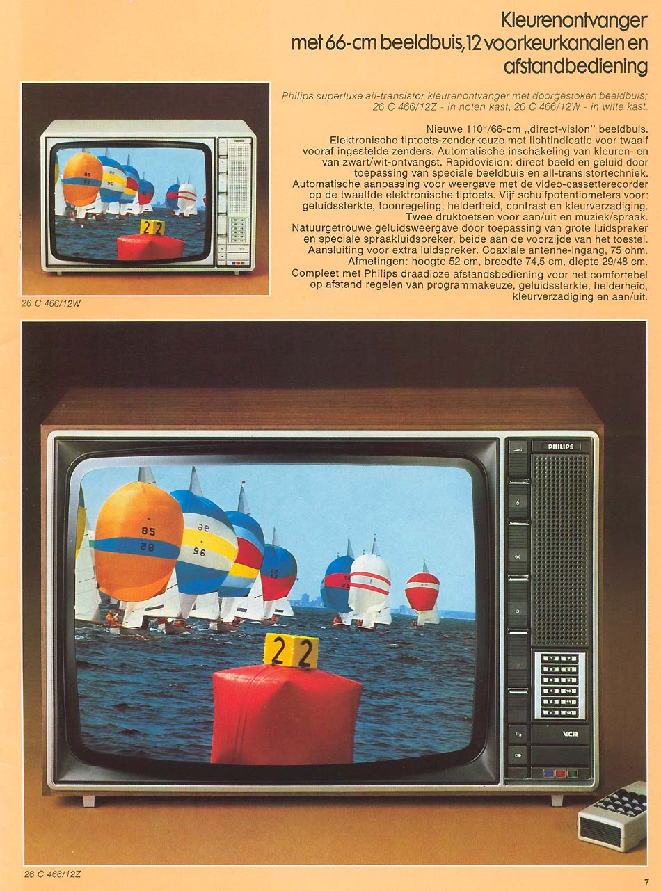
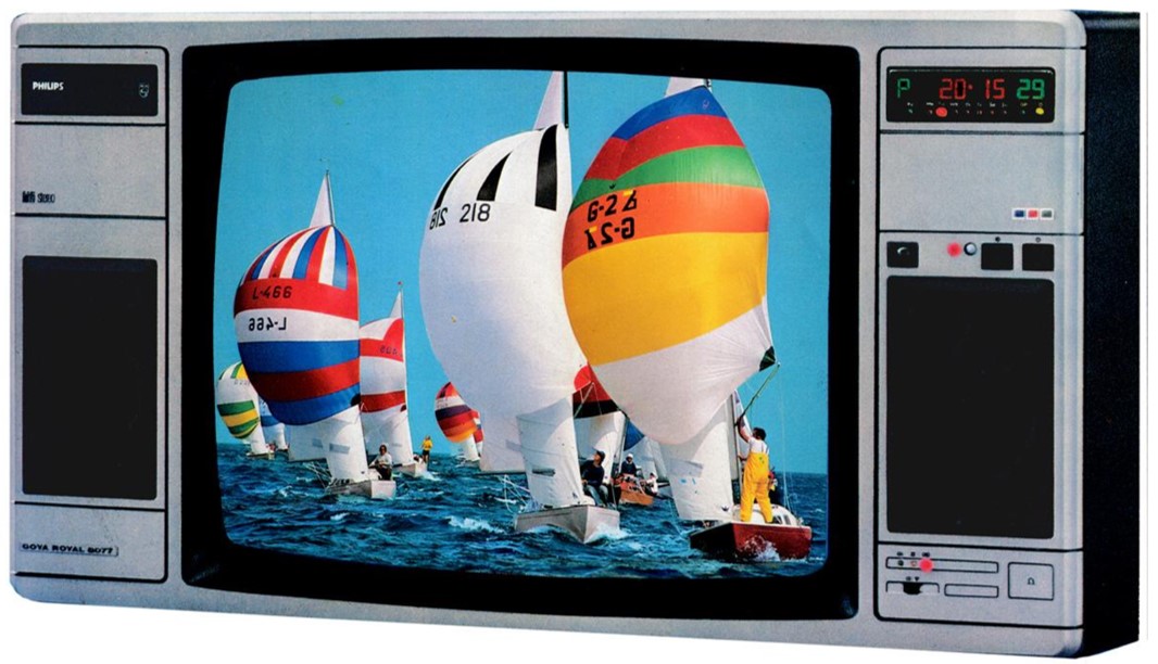
The first generation remote control, still being a relatively expensive feature, was introduced on a limited scale, and only for the most high-end TV sets. This was the new 1972 K9 colour TV chassis, the first one that was fully transistorized. The X26K201 to 209 mainly differed through their user interface, from the earlier push buttons (X26K201) to touch sensors (X26K202), larger sliders (X26K206), and finally remote control (X26K209). The K11-chassis, which was essentially a K9 upgrade with the new 110degrees 66cm direct vision picture tune, and in Krefeld even called K9i, re-used most of the K9 including the cabinet and remote control. The 26C463 and 466 externally therefore look identical to the X26K209. Overall, these were the only three TV models that used the RC1 first generation remote control.
RC2, 12-program remote control, 1975
|
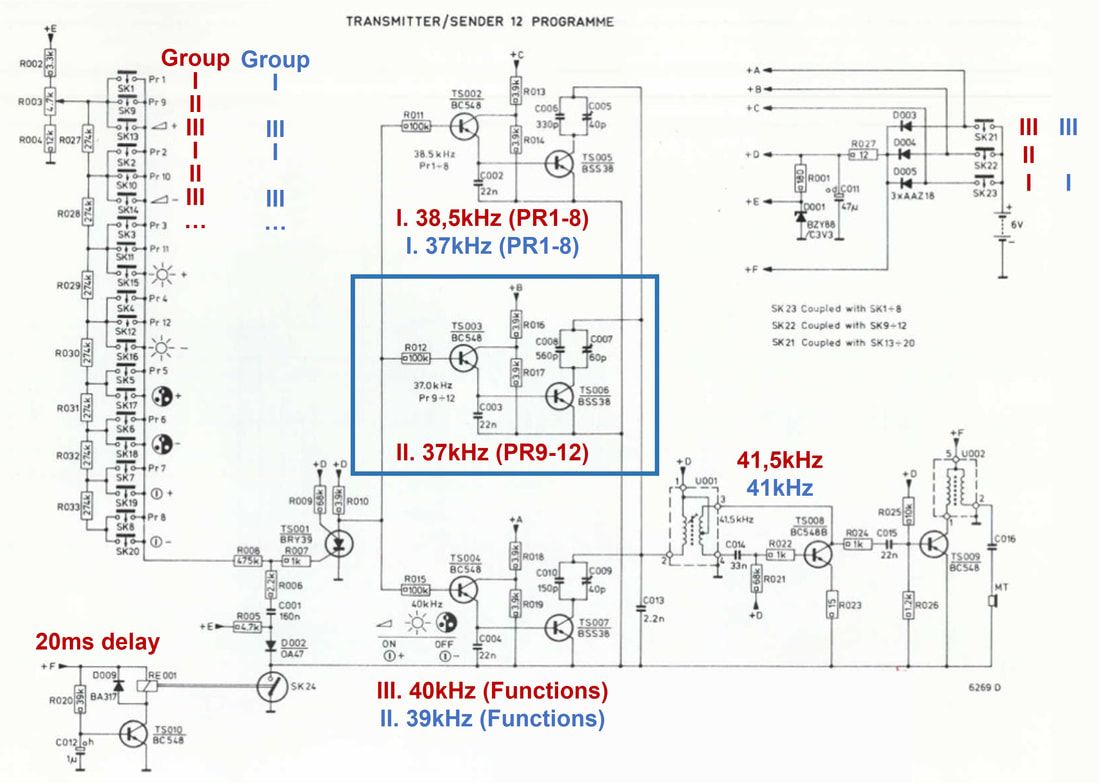
It seems that the development of the first generation ultra-sonic remote control, given the innovative character and the complexity, took several years to completion and final product launch. From say 1968 to 1972, when it was introduced. Development of the ultra-sonic functions took place in the Edens-lab tuner development in Eindhoven. However, once successfully launched it is logical to expect that there was the push to concentrate the entire remote control development in one group. It is logical to assume this happened latest in 1973, when Edens retired and the tuner activities were integrated with the Elcoma tuner development. Given the rapid developments of especially integrated circuits, the RC1 was conceptually already outdated by the time it was launched, and therefore a second generation development was started in parallel to the launch of the first generation. Its main objective was - apart from modernization of the electronic components - extension of the number of channels to 12. A third group was therefore added to the transmitter, although the base concept remained the same. The up-down program counting of the RC1 was also deleted, so only the function-group still required detection of the second burst length.
|
|
However, the frequency allocation was re-shuffled and became (from low to high) 37kHz for PR9-12, 38,5kHz for PR1-8, 40kHz for the functions and 41,5kHz for the second burst.
There three concept changes in the transmitter architecture compared to RC1: 1. all buttons now used a single resistor ladder network. 2. the three group oscillator driver circuits were copied and no longer a single circuit with internal switches. Switching occurred at the power supply (SK21-23). 3. the mechanical delay switch SK24 is replaced by a relay-operated switch. |
|
For an 8-program version, backward-compatible with the RC1, the PR9-12 Group was omitted and the the remaining two groups tuned to the original RC1 frequencies. But apart from this, the transmitter largely remained the same, at least electrically. The mechanical design changed to accommodate the higher number of buttons, making the handheld module even larger!
|
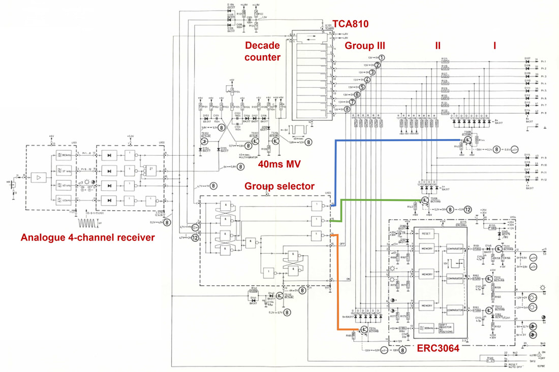
The biggest changes of the RC2 were in the receiver. Although it obviously had to deal with a fourth frequency, this was a simple extension with one detector branch. But because the program up/down counter was no longer required, and because a dedicated Philips IC was developed for the digital-to-analogue control of the three functions (volume, clarity, contrast), the architecture was substantially simplified:
- a single decade counter was used for all three groups.
- a single a-stable multi-vibrator was used, with 40ms interval, omitting the 300/650ms multi-vibrator.
- a new Group selector determined to which control inputs the outputs of the decade counter were connected.
- the analogue volume/clarity/contrast control was done using pulse width modulation inside the new IC ERC3064.
|
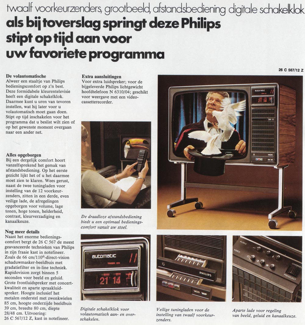
As postulated earlier, the RC1 solution, especially the receiver, was probably outdated at introduction, and the RC2 2nd generation was therefore pushed into production as soon as available. It was thus introduced halfway the K11 chassis lifetime, a quite unusual approach that supports the assumption. It was introduced in the 1975 versions of the chassis in two forms. The RC2A was the backward compatible 8-program version, used by a single set, the 26C561, probably for compatibility reasons with the earlier K11 sets 26C461 and 466 that still used the RC1 system. (From then on the RC1 was no longer available as a service solution, the RC2A being offered instead). But the 12-program RC2B was used in more sets, the 26C549, 566 and 567, plus the Krefeld Goya sets. As already mentioned, the RC2C was substantially bigger than its RC1 predecessor.
|
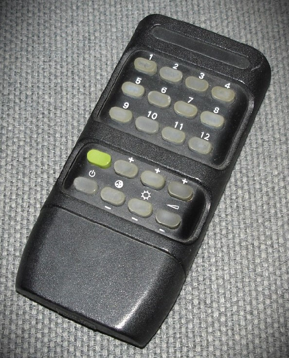
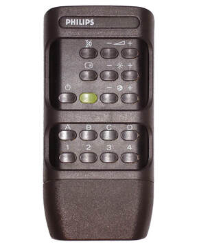
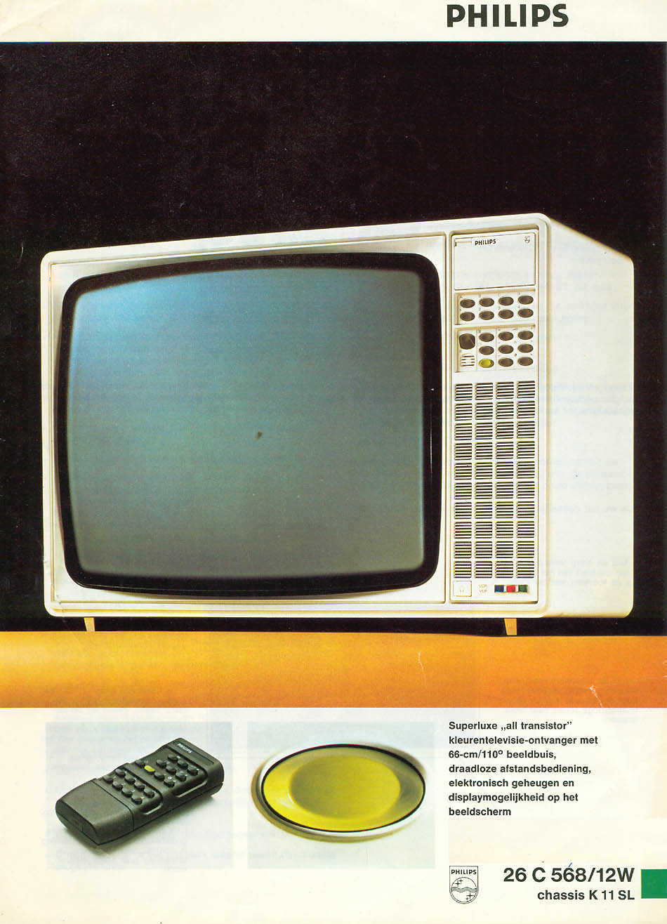
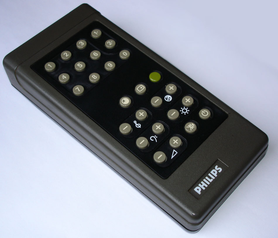
A final derivative was developed as the RC2C or RC2-digital version for the 26C568 set. This was the first TV set using on-screen display of control settings through the use of horizontal bars. This required much more digital control inside the set, and the digital-to-analogue conversion of the control signals of the ERC3064 IC was no longer required. This was in principle only a simplification of the receiver. The program selection was also modified, however, supporting 16 programs. To this end the programs were clustered in 4 groups (A-B-C-D) and four programs per group. A program was thus always selected by a group-program combination. This reduced the number of RC buttons for program selection to 8, although the user friendliness did not improve. The now available buttons were used for additional Mute, On-Screen-Display and the new Personal Preference green button.
|
|
With the RC2C the two generations of ultra-sonic remote controls ended, the next generation introduced infrared control. In the end the ultra-sonic concept lived only briefly, from 1972 to 1978 roughly, or in other words only in connection with one set under the K9 chassis, the K11/K9i chassis, and one set under the K12 chassis. But despite this short life it was an important milestone in the world of television, introducing the wireless remote control. And where at least for the ultra-sonic RCs Philips only used them in high-end sets, they paved the way for the general remote control use as we know it today. In the K12 chassis the RC became a much more standard feature throughout the chassis. As such it was an interesting design, all more so since its (ultra-sonic) origins lay in the Edens tuner lab.
|
RC4, the first infrared remote control, 1978
However nice the ultra-sonic remote control, it had its limitations. For one it was (still) bulky, but that was probably not the biggest issue and there was lots of room for future size reduction. The major limitation was related to the rather crude protocol, with a limited number of frequencies and rather long pulse times. It was therefore difficult to expand the number of functions beyond the ones implemented in the RC2 family. A fundamental change was thus required, and that was infrared (IR) transmission based on 940nm Light Emitting Diodes (LED). LED's had been around for some ten years already, but only as signal elements, replacing the old light bulb. But over time LEDs had become smaller, technology improved and therefore also the bandwidth.
|
The IR-RC was planned to be introduced with the new, much more digitized K12 CTV chassis. This involved a number of major architecture and concept changes within the entire television control system. Briefly summarised these were:
|
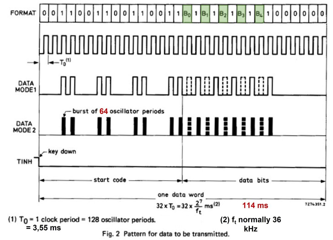
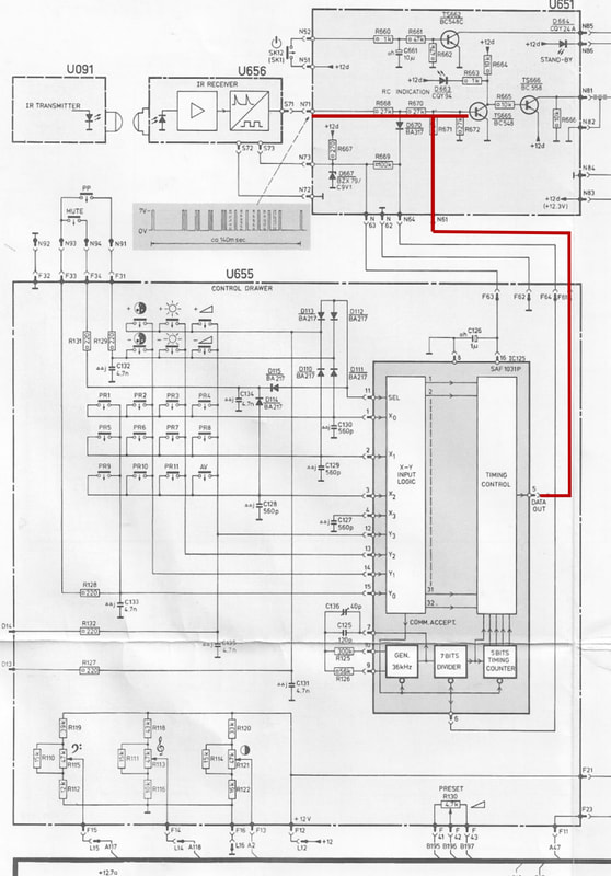
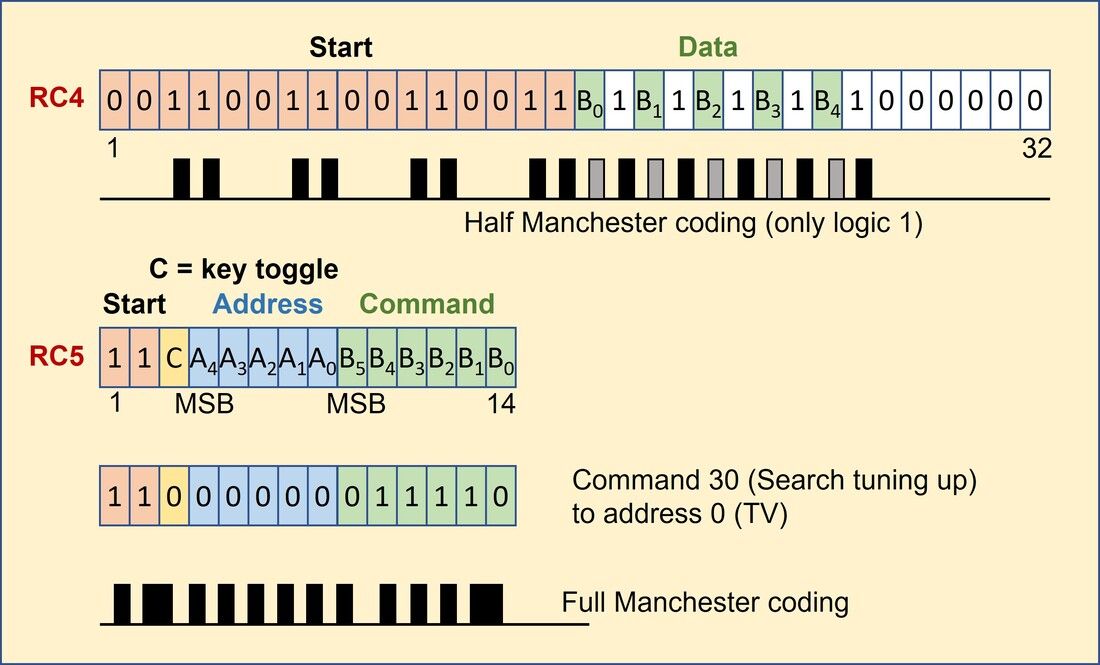
- Especially with this first generation IR remote controls there was fear of interference. The protocol thus required that the 114ms 32-byte data word was re-transmitted at least once, 114ms later. In the receiver the first decoded data word would be stored and compared with the second reception. Only if both words were identical it would be further processed.
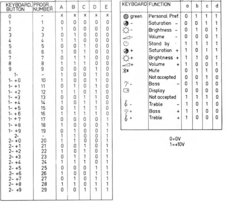
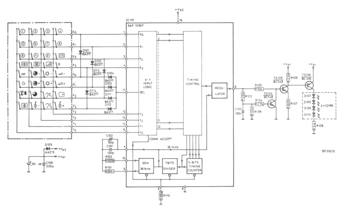
- With the 5 data bits 2^5 = 32 commands could be encoded. For this Philips Semiconductors developed a first generation MOS IC, the SAF1031. To reduce input contacts to the IC it used a matrix structure for the remote control buttons, divided into two 4x4 matrices, one used for the program selection and one for the control functions. The two matrixes shared the 4 X- and Y-inputs while a SELECT input was high in case of the lower control matrix. The IC then translated these inputs into the associated 5-bit data word for transmission. A HEF4011 MOS IC then acted as a (half) Manchester modulator.
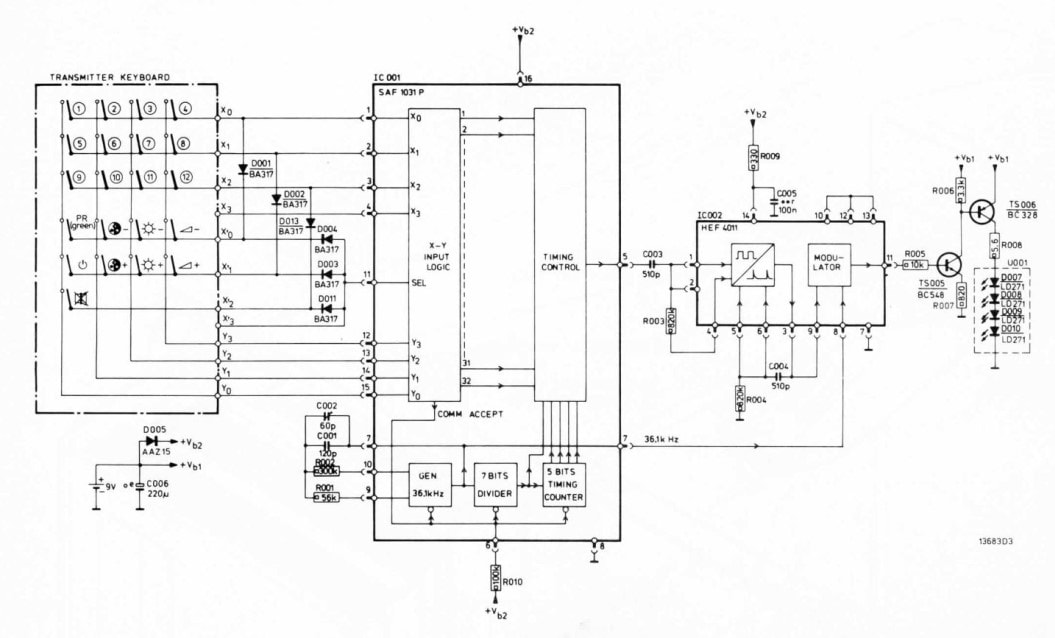
First generation IR remote control transmitter as used in the RC3 and first RC4 remote controllers. To increase the light output the remote controllers used four LED's in series, that could be mounted on two edges of the RC front for a broader field of view. [Philips K12 26C849 and 857 Service Manual]
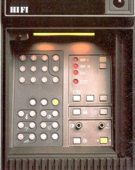
This new control system was introduced in one of the last K11 sets in 1976, the 26C657, albeit with two restrictions: - the SAF1031 was not yet used inside the TV set, instead using more classical control switch constructions. - the remote control function still used the RC2 mechanics and form factor, which was now called RC3. This set was essentially a test platform for the new control system that was the core of the new K12 platform. The K12 chassis was introduced in 1976/77 with the basic models, followed by the high-end models in 1978 which now used the SAF1031 in the TV and introduced a new, sleeker remote control form factor. This was the RC4 generation. There were multiple variants of this RC family, called RC4A to RC4G, which differed in the number of control buttons but were conceptually all identical. Different versions were made for other devices, like the Video Long Play VLP700. Secondly, the remote controller was upgraded with the new SAF1039P IC, which was one the one hand an integration step with the Manchester modulator. And secondly it was a technology migration to the first real CMOS technology, with complementary NMOS and PMOS transistors. Still operating at 9V power supply! |
During the lifetime of the RC4 some further improvements were implemented. Firstly, the main need for extension was in the number of programs that could be controlled, with 12 quickly becoming insufficient. The RC4C extended the number to 16 in the classical way by increasing the number of program buttons to 16. But with the RC4D a new concept was introduced with the "1-" button: for program numbers between 10 and 19 first the 1- button was pressed and then the second digit button. From the RC4E this extended to 29 programs by adding the "2-" button.
|
RC5, the "world standard" remote control, 1982
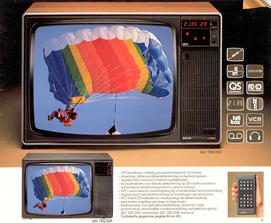
The K12 chassis and its infrared RC4 remote control can be considered to be a major success, essentially creating the need for remote control in every TV, but also in other consumer devices like video cassette recorders (VCR). And just like in the RC2-to-RC4 switch, again the RC4 concept was already too cramped after just one chassis generation. For the K12Z, an upgrade of the entire control system was made through the switch to the so-called new Long-F8 platform. In conjunction a new remote control standard was introduced, the RC5.
|
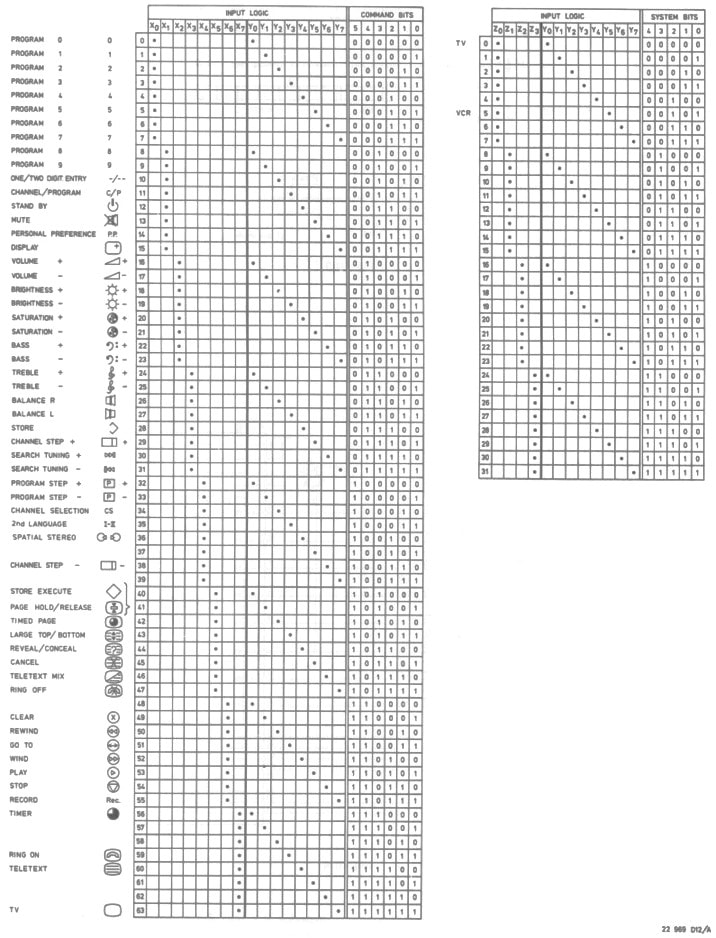
As observed earlier, the RC4 code was very inefficient (only 5 data bits of a total of 32), but apparently designed for robustness. Real life and field measurements had, in the meantime, probably led to the conclusion that this extreme robustness was not required, and the RC5 code was much simplified. Especially the start sequence was reduced from 16 to just 2 bits. The transmitted data was now split into two groups: a 5-bit address (also called System Bits) that indicated the type of device being addressed (TV, VCR, STB and later many more) and 6 bits to send any of 64 commands. Bit 3 was the key toggle bit, which toggled every time a button was pushed. Using this bit the receiver could see whether a RC key was kept pushed or repeatedly activated.
|
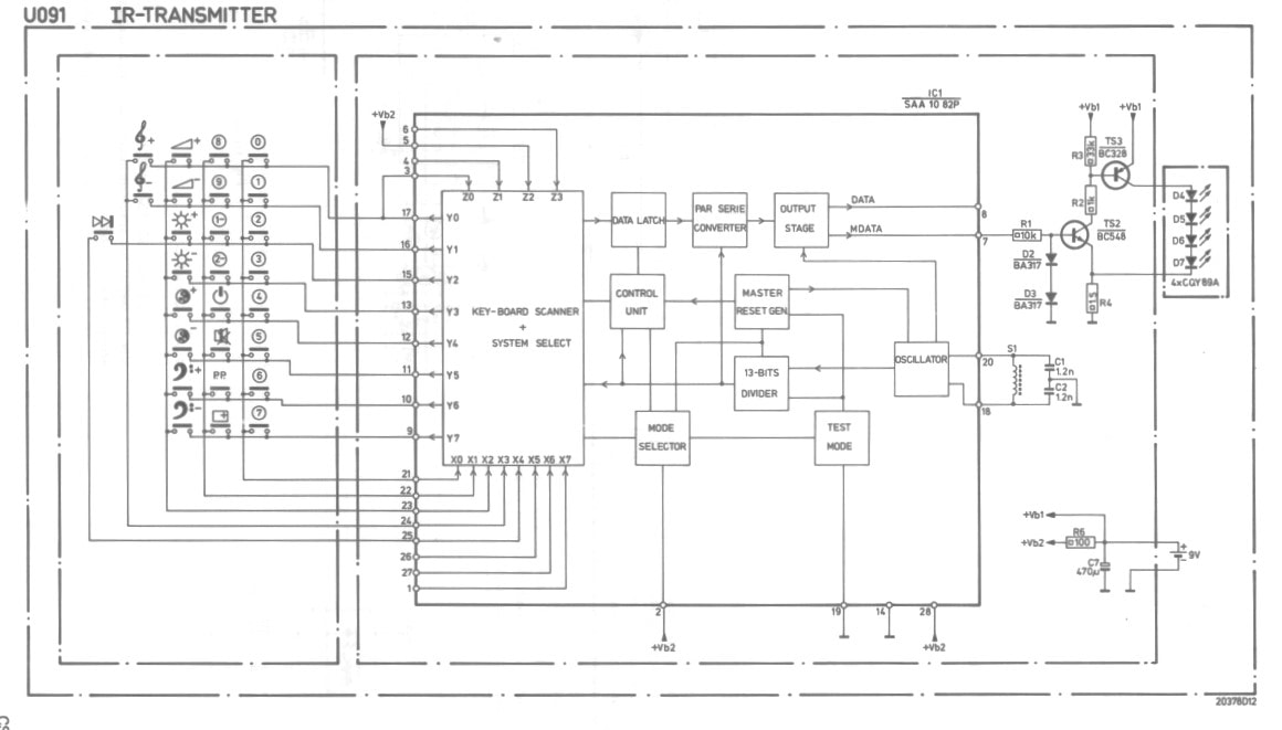
The total message length thus reduced to 14 bits compared to the 32 of the RC4. Most other parameters were kept unchanged, however: the 36kHz centre frequency, bit length of 3,55us, and the message repeat time of 114ms. One change, though was that now the full Manchester bi-phase coding was used, also encoding the logic 0's as 1-0 bytes. Of course this new standard required a new encoder IC, which was the Philips Semiconductors SAA1082P, mostly likely a Southampton designed and produced IC. It had eight X and Y inputs, supporting a full 8x8=64 commands matrix without the diodes from the previous generations.
|
The RC5 remote control was introduced together with the K12Z in 1981/82 and immediately established itself as the "ultimate" remote control. The 64 commands allowed all desired remote control operations, the 5 system bits supported for the first time multi-device control with the same RC. At least short-term there was no longer the need for yet another generation or standard, which meant that the solution stabilised and supported the usual aggressive cost reduction required for consumer electronics. This in turn made that the remote control became mandatory for every television set, down to the low-end range. Which increased volumes to much higher levels, further reducing the cost. This was further supported by Philips Semiconductors selling the ICs to other set makers too. As a result the RC5 became the de facto world standard for remote controls for the decades to come. The huge volumes associated with these developments eventually made the remote control very cheap, by 1996 at the time of the famous L7 chassis the RC was less than 1USD.
In 1991 remote control volumes became big enough to justify a dedicated Business Line under the Business Group TV (BGTV), which was created in Leuven, Belgium, as a compensation for the rapidly reducing audio production there. Similar to the sister business BU Tuners all remote control development was now concentrated under this single BU, allowing scale optimization. Later the BU-RC moved out of the former audio fab in central Leuven to a new site at Haasrode, south of the same city. From 1995 it also started to sell remote controls to other set makers, similarly to the BU Tuners. With this my analysis of the birth of the TV remote control ends. In 30 years it had evolved from a wired box with three controls, through the first wireless ultra-sonic modules to the infrared remote control. |
|
References
The references for the remote control history are very similar to those for the TV and Tuner histories. The main ones remain:
- Radiomuseum.org, especially for the old wired and first ultra-sonic generations
- Elektrotanya, Nostatech and NVHR for the Service Manuals of most of the mentioned Philips TV sets
- Datasheet Archive for old IC data sheets.
- Marcel's TV Museum for nice set pictures
Page update history
- November 2022
First upload.

