
|
The entire content of this web page, plus much more, can be found in the book shown left, the first part of the Philips Technology History series.
For details and ordering information please see the dedicated page ordering my books. |
Introduction
|
We're now at the end of the 1950-ies, after almost 15 years of TV tuner development within Philips. The modules had steadily grown in functionality and maturity, covering up to 12 channels in the VHF domain, with internal AGC and if desired AFC control. The sensitivity had step-wise improved with the introduction of ever new valves, moving from the EF42 to the EF80, ECC81, PCC84 and PCC88, in combination with the PCF80 mixer-oscillator. In this series of improvements the PCC88 was the first of the frame grid valves, which offered a very clear improvement due to their smaller internal construction, and valve developments in the coming period will be dominated by frame grid valves:
|
Chapter navigation
|
Tuner basics 7 - UHF reception
Once television broadcast took off it became clear that the number of channels allocated to it, (in Europe) 4 in VHF I and 7 in VHF III, was much to low to accommodate all potential broadcast programs. This was aggravated by the need to avoid adjacent channel interference, which meant that not all channels could be transmitted from the same location, and careful nation-wide frequency planning was required to avoid interference. Naturally this issue occurred first in the US, where TV broadcasting had started as early as 1943 and the number of broadcasters was highest. The natural solution to this problem was - and still is today! - to move to higher frequency bands, where more bandwidth is available. For television this was the Ultra High Frequency (UHF) band which formally runs from 300 to 3000MHz. The US allocated 60 channels from 470 (Channel 14) to 884MHz (channel 83) which were fully compatible with the VHF NTSC (CCIR-M) standard, so 30Hz frame rate, 525 lines, negative modulation and FM sound in a 6MHz channel bandwidth. The large scale roll-out of UHF broadcasting started in 1953-54, with a few hundred stations nation-wide. Results were disappointing, however, mainly due to bad receiver performance, the resulting short range and limited area coverage. Many of the stations went bankrupt in the following years and by 1958 only 9% of television sets contained a UHF tuner (vs. 35% in 1953). It was only in 1965 that the FCC made UHF tuners mandatory in all US TV sets.
|
Europe followed a few years later for two reasons. Firstly VHF television broadcast only started in earnest during the first half of the 1950-ies and it took a few years before an actual channel shortage made itself felt. Secondly introduction was effectively awaited till good technical solutions were available, avoiding the "trough of disillusion" as experienced in the US. The technical breakthrough required was the Philips PC86 UHF triode, using the new "frame grid" (, sometimes also called "guided grid", in Dutch spanrooster) construction. With this concept, the structural stability of the grid windings was provided by a separate molybdenum frame, with the thin grid wires wound around it tightly. This allowed much finer grid windings, typically 10um wire with 50um spacing. The frame tolerance was 5um, the wire positioning tolerance 0,2um. This in turn resulted in smaller grid-to-cathode gaps and ultimately almost twice higher transconductance gm of the triode. The PC86 offered 14mA/V at 12mA anode current and 175V anode voltage. The valve was introduced mid 1958 (together with its EC86 equivalent for parallel 6,3V heater supply), and first tuners appeared in 1960.
In parallel one other standardization took place. Whereas the US kept the VHF and UHF fully compatible, using exactly identical CCIR-M standard parameters, resulting in 6MHz UHF channels, in Europe there had always been a push for higher quality television. And the original Russian standard proposal - which became CCIR-D - had already proposed (and then used) 8MHz channel width. Although France with its 819-line 13MHz standard (CCIR-E) had been pushing higher bandwidths from the beginning, for practical technical reasons (and probably also political reasons for not wanting to adopt a Russian proposal) the other West-European countries had settled on 7MHz bandwidth for the VHF (CCIR-B). With the large bandwidth coming available in the UHF band the general consensus was to use at least part of this for larger bandwidth and thus better quality. As a result the West-European standard CCIR-G introduced 8MHz channels at UHF, resulting in 49 channels between 470 and 862MHz. All other parameters of UHF CCIR-G remained identical to those of VHF CCIR-B, which meant that the effective quality improvement was limited due to the continued 5MHz video bandwidth, and mostly secondary, due to more adjacent channel distance and less steep filtering with the associated signal distortion. UHF was introduced first in Germany in 1960, mainly to fill gaps of the main VHF transmitters. This resulted in many UHF transmitters in the border regions (like e.g. Aachen), channels also watched by the neighbouring countries. So although they initially didn't implement UHF transmissions themselves, countries like the Netherlands, Belgium and Denmark saw a UHF demand parallel to that in Germany. The UK introduced UHF in 1964, and combined this with the introduction of 625-line CCIR-I, which was identical to CCIR-G apart from the video bandwidth, which had been increased to 5,5MHz (vs. 5MHz). As a consequence the sound carrier also shifted 499,6kHz to almost 6MHz. This meant that from that moment onwards UK TV sets became dual standard CCIR-A and -I. Likewise in France, which introduced another modified 625-line standard (CCIR-L) requiring dual standard receivers, although system L was also used in VHF to replace the old system E. Transmissions started December 1961. A last exception was again Belgium, which introduced CCIR-G but with a larger 1,25MHz vestigial side band for compatibility with the French system. This became CCIR-H. After the introduction of UHF receivers for Belgium effectively became 5-norm sets due to the French UHF 6,5MHz sound! Like the US, eastern Europe was able to keep all its parameters identical when moving from VHF (CCIR-D) to UHF (CCIR-K). |

The Philips PC86 UHF triode. The active part is only the lower dark grey section, which is small to minimize parasitics. Note the gold-plated pins for lower contact resistance. [Franks Tube Data]
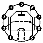
To reduce parasitic series inductances all three electrodes had multiple pins allocated: two for cathode (3,7) and anode (1,9) and even three for the grid (2,6,8).
|
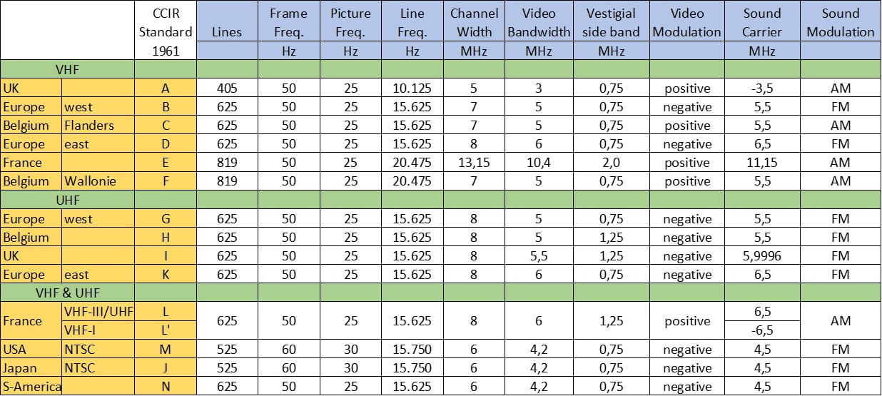
Overview of both the older VHF and new UHF television broadcast standards. Clearly the alignment to similar standards has succeeded much better in UHF than in the older VHF. All non-US standards have converged on 625 lines, with minor differences mainly around the sound-to-video carrier distance.
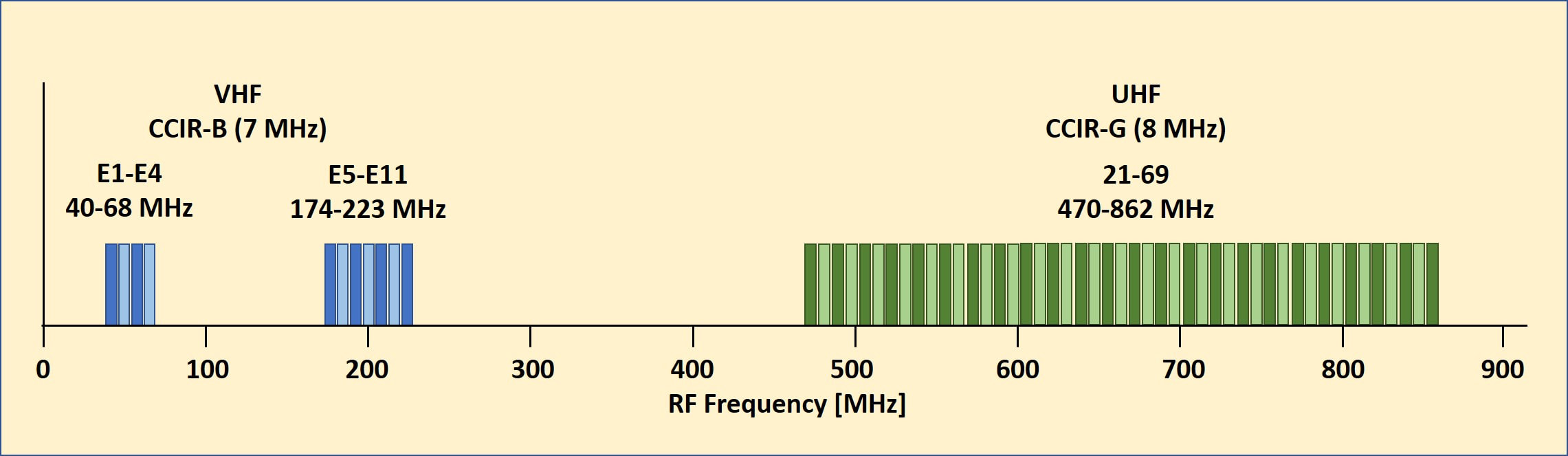
The final frequency spectrum allocation for television broadcast, here shown for the (Western) European standards CCIR-B (for VHF) and CCIR-G (for UHF). Theoretically 60 channels were available across all three bands.
AT6321, the first UHF tuner, 1959
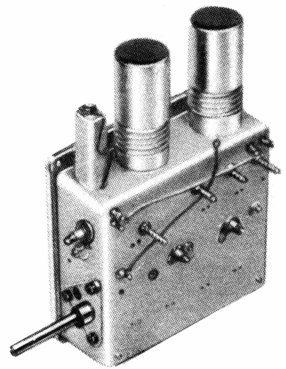
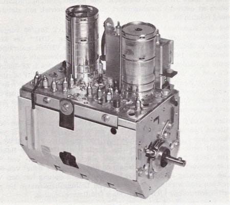
Making good UHF tuners by the end of the 1950-ies was a challenge. Mediocre performance of the tuner could destroy the complete UHF application, as the early US experience had shown. Main parameters to focus on were sensitivity (input Noise Figure), sufficient amplification and radiation, especially of the oscillator frequency. Because UHF signals close to 1GHz easily leak and radiate through any opening or ungrounded conductive surface, the basic construction of the UHF tuner had to be different from the VHF tuner used up to then. The latter was a metal frame with screwed-on cover plates, but this was totally insufficient for UHF. The solution was a single cast box (most probably cast iron, sink-plated) with five isolated chambers separated by fully closed walls. Because of the form it was often referred to as the "bath tub". It was tightly closed by a single aluminium lid. The two PC86 triodes were mounted on top, where the valve sockets were the only signal bridge between chambers 1 and 2 (the preamplifier valve) and 3 and 4 (the mixer-oscillator valve). Holes through the walls were kept to a minimum and only for the main signal (two between chamber 2 and 3, one between 3, 4 and 5 each) and the heater wires. For heaters, AGC and supply voltage ceramic feed-through capacitors were used.
|
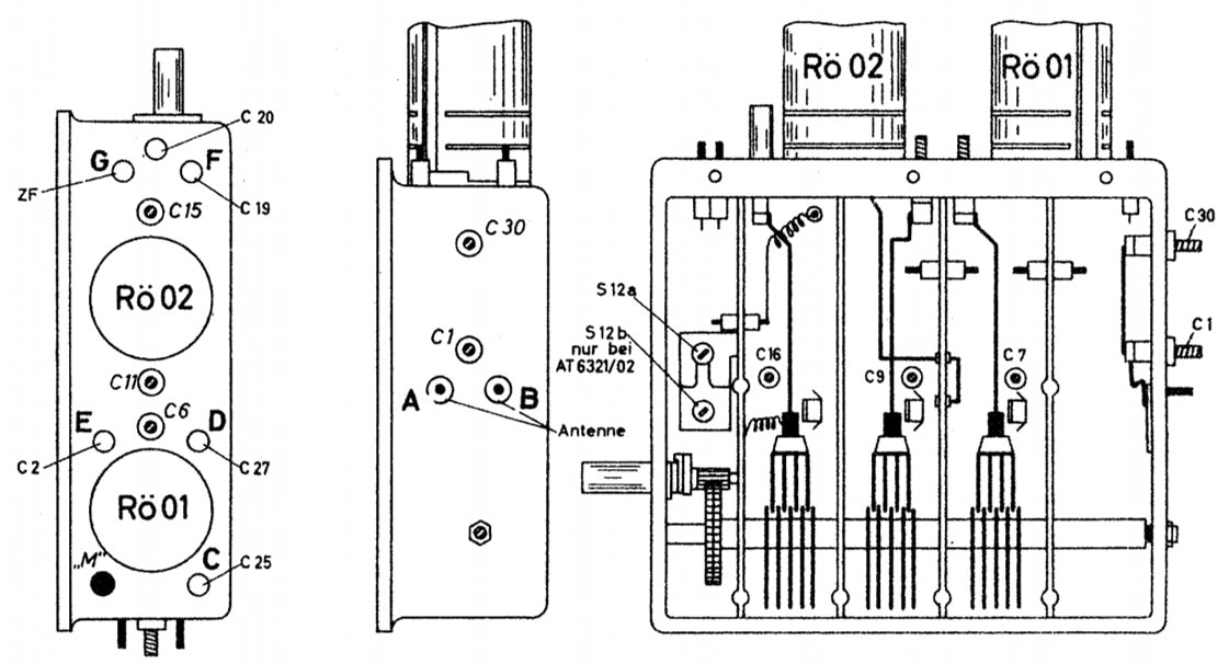
The tuned circuits were all based on pi-filers (C-L-C), where the inductors were formed from thin metal strips of roughly a quarter wavelength at the centre frequency 650MHz (12,5cm) which was shortened with a series capacitor to around 6,5cm (1/8th the wavelength). In contrast to the VHF tuner the input matching filter was not tuned, leaving only three tuned filters: the primary and secondary of the inter-stage bandpass filter and the oscillator tank circuit. These three filters were capacitively tuned, with three variable air blade capacitors. With a non-constant blade radius this provided a more or less constant frequency tuning behaviour. To provide tuning accuracy there was an internal 1:5,4 gear construction, while on the external control knob a further 1:8 reduction was required, providing an overall 1:40 fine tuning reduction factor. Finally on the first tuner the alignment screws for the filter were all accessible from the outside, mostly from the backside (C4, C12 and 13, C20 and 21, C25) while the bottom capacitor of the tank circuit C27 could be accessed through a hole in the right (output) side. This first UHF tuner was introduced in 1959 as the AT6321 module family, with the factory code of the first implementation KR 361 60, indicating it was produced in the Krefeld television factory. Note that these first generation UHF tuners did not cover the full 860MHz range, but only up to 790MHz.
|
The first Philips UHF tuner KR 361 60.
|
AT Modules naming
The Eindhoven UHF tuners were coded in the AT-series of modules, with A= Electronic module and T= for Television. However, there does not seem to have been more structure applied then that, and modules were simply numbered chronologically. So
AT6320 = TV wired remote control AT6321 = UHF tuner AT6325 = 3rd-party tuner AT6327-20 = UHF retrofit tuners Etc. |
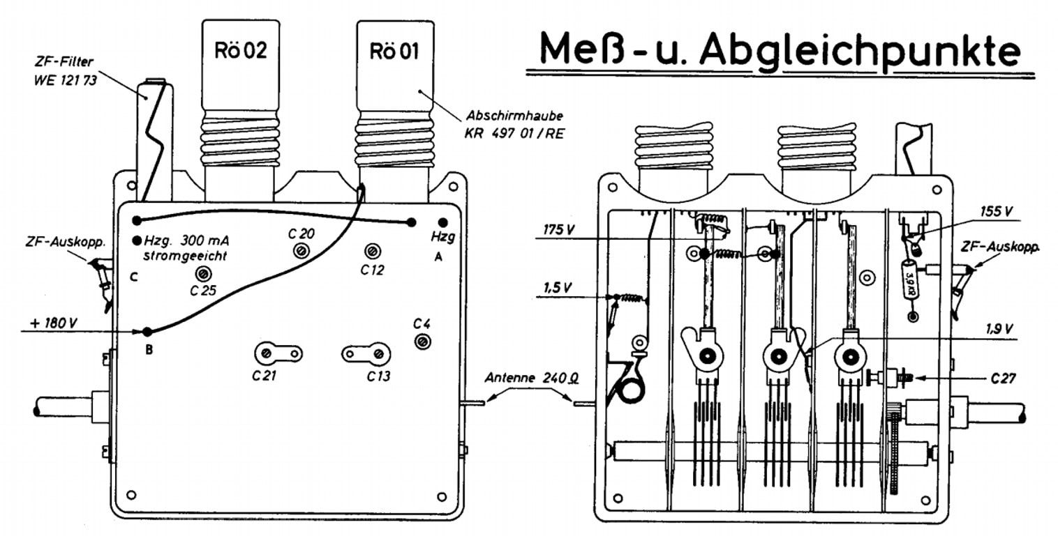
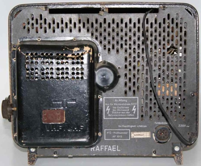
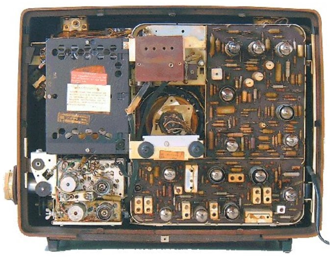
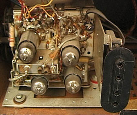
The external view and internal mechanics of the Philips KR 361 60 UHF tuner from 1959. [Philips KR 361 60 Service Documentation]
|
|
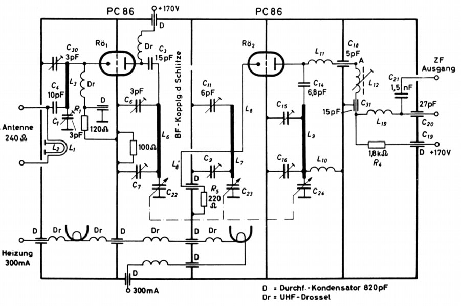
Because parasitics needed be kept under control the design of the UHF tuner is at least schematically simpler than its VHF counterpart. No fancy cascode input stage, nor the luxury of separate mixer and oscillator, but instead a single grounded grid triode pre-amp and a similar grounded-grid self oscillating MO triode.
The input has been kept very basic: first a half-wave balun for symmetrical-to-asymmetrical conversion, followed by a broad non-tuned pi-filter, where the bottom capacitor C4 is aligned for maximum input matching to the PC86 cathode input in combination with a good antenna matching VSWR. |
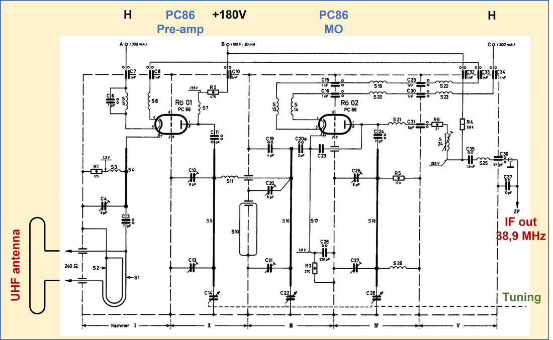
Circuit diagram of the Philips KR 361 60 UHF tuner. [Philips KR 361 60 Service Documentation]
|
Hard grounding of the PC86 grid has the advantage of eliminating the influence of Cag feedback, but reduced the gain of the stage to the input and output impedance ratios. However, the impedance of the primary load filter was higher, providing for both gain as well as a narrow bandwidth for selectivity. In fact the bandwidth of the integral bandpass filter was kept fairly constant at 8-12MHz across the tuning range, which I consider quite an achievement for a commercial volume product like a TV tuner. Because the filter is so narrow it also means that the attenuation of the image frequency (fLO+IF or Fc+2IF) was 180x (45dB), while the reverse attenuation of the IF towards the input was 1000x (60dB). The coupling between the primary and secondary sides of the filters, which were located in separate chambers 2 and 3, was obtained through a simple metal wire loop S10 through the side wall. All filters had double alignment at the top and bottom, with the tuning capacitor at the "cold" bottom end of the wire inductor.
The 2nd PC86 acts as a self-oscillating mixer, where the tank circuit is connected between the anode and ground. Feedback is provided by C23 directly from anode to cathode. However, at the anode is also the IF filter, which is effectively parallel to the tank circuit. To avoid de-tuning of the IF filter tuning oscillator tuning (due to the changing parallel complex impedance of the tank circuit), the tank is loosely coupled to the anode through C24. Furthermore, at the bottom of the tank inductor S26 short-circuits the tank to ground for low frequencies.
The 2nd PC86 acts as a self-oscillating mixer, where the tank circuit is connected between the anode and ground. Feedback is provided by C23 directly from anode to cathode. However, at the anode is also the IF filter, which is effectively parallel to the tank circuit. To avoid de-tuning of the IF filter tuning oscillator tuning (due to the changing parallel complex impedance of the tank circuit), the tank is loosely coupled to the anode through C24. Furthermore, at the bottom of the tank inductor S26 short-circuits the tank to ground for low frequencies.
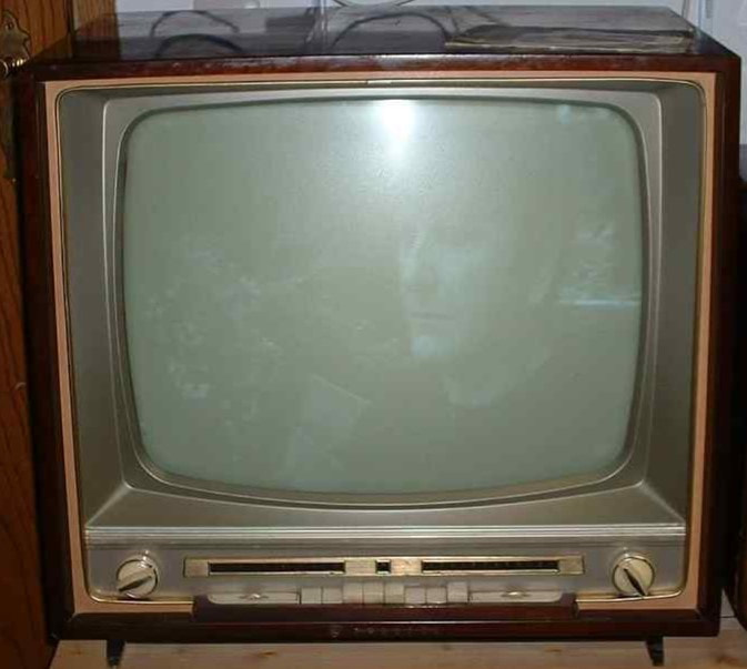
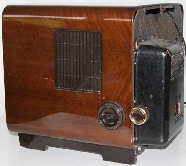
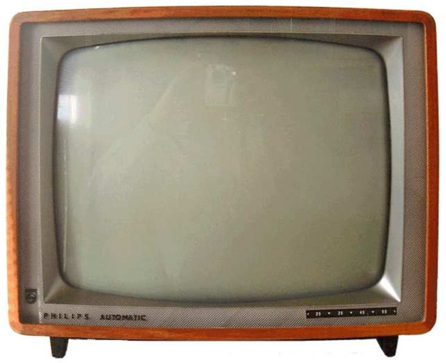
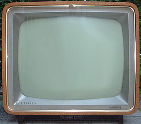
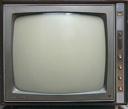
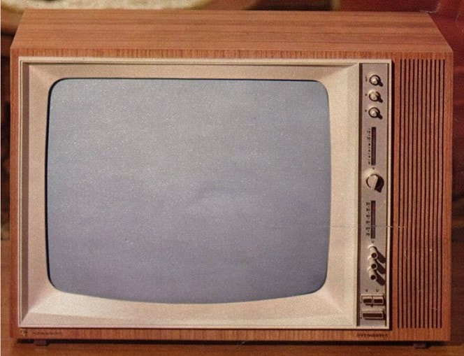
The Philips 23TD293 from 1959, the first set designed for the new UHF tuner. [RadioMuseum.org]
|
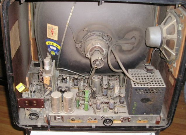
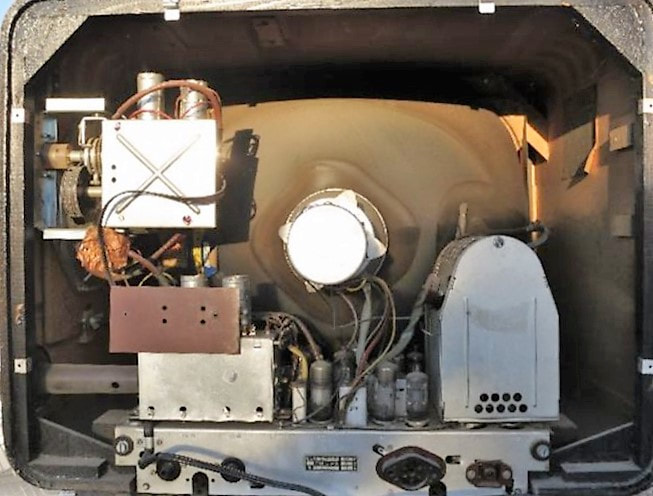
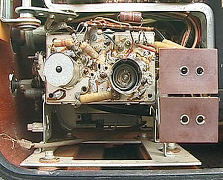
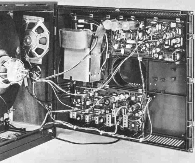
Interior view of the Philips 21TD293, with on the left the UHF tuner mounted on the edge of the chassis. [RadioMuseum.org]
|
|
The KR 361 60 UHF tuner module was launched in 1959, although mainly as after-sales service upgrade to older or new TV's. From 1959 almost all mid to high end sets were "UHF ready" which meant that a VHF-UHF switch was installed and the power supply and IF connections for the UHF tuner foreseen. When purchasing a new television the UHF tuner was e.g. offered as a feature at an excess price of 98 DM in Germany. Only the most high end sets like the console 21CD293A Leonardo Vollautomatik were equipped with the KR 361 60. This situation didn't change dramatically until 1963, from which date most Philips TV's received a UHF tuner as standard block. In the meantime TV set owners had an alternative in the form of external UHF-to-VHF converter boxes, a Set Top Box avant la lettre. Philips launched the NT1152, in 1961, although the product coding suggests there were an NT1150 and/or 51 before. This box used a modified UHF tuner but with two important modifications:
|
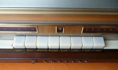
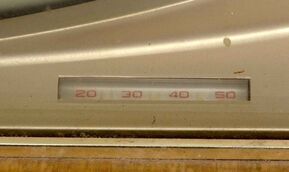
The control section of the 23TD293A. On the right the two band switches for VHF and UHF, above them on the right the VHF channel indicator, on the left the UHF tuning indicator. [RadioMuseum.org]
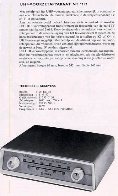
1962 Advertisement for the Philips NT1152 UHF-VHF converter. [1962-63 Philips Television Product Overview via Oudio.nl]
|

Front view of a unique surviving NT1152 UHF-VHF converter. [via TacoVonk]
|

Backside of the NT1152 with on the left the antenna input and loop-through output, on the right the power supply switched loop-through output. [via Taco Vonk]
|
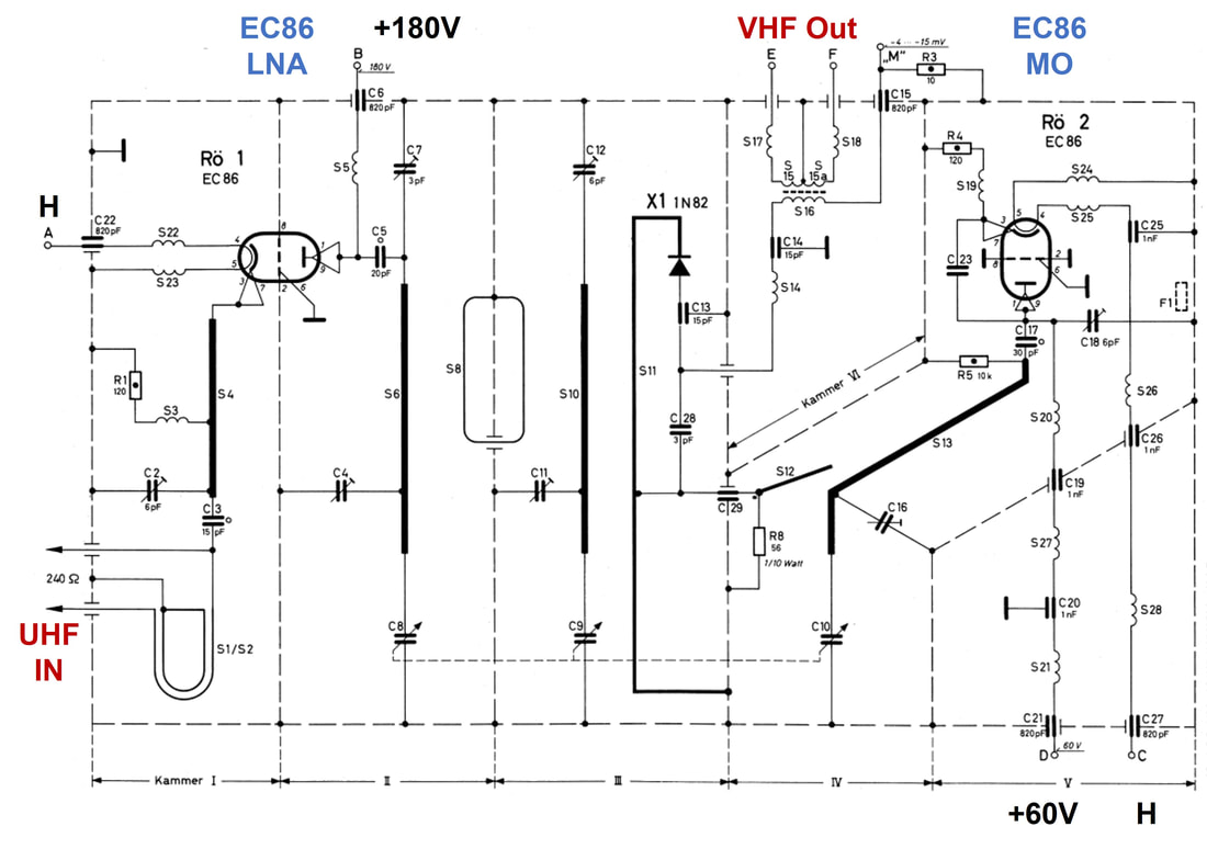
Circuit diagram of the Philips KR 361 87 UHF-VHF channel converter. S11 is the coupling loop between the BPF (S6-S10) and the IN82 mixer. S12 is the coupling inductor between the oscillator and the mixer. [Philips NT1152 Service Manual]
|
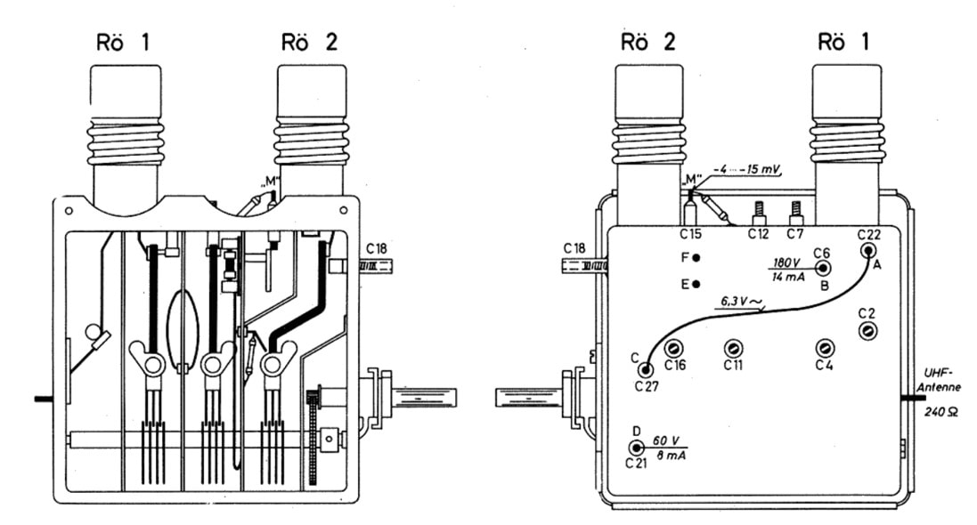
Mechanics view of the Philips KR 361 87 channel converter. Note that, like in the KR 361 60 first UHF tuner, the RF input is on the left side of the opened tuner. [Philips NT1152 Service Manual]
|
UHF retrofit and service solutions
|
As already mentioned, one of the issues with which set makers struggled after the introduction of UHF was the by now large installed base of television receivers with only VHF tuners. Many of these set owners also wanted to watch the new channels on UHF and demanded upgrades of their sets, which were at the time still pretty costly and definitely not today's throw-away electronics. So, from the moment UHF was introduced there was the need for retrofit upgrades of existing sets by adding a UHF tuner. This could only be done on sets starting from the TX250 family, the first that was "UHF-ready". This meant they had the power supply lines available, and the VHF-UHF switch available on the front panel. Adding a UHF tuner then meant following changes:
|
This was a chassis before the TX250, and thus formally not supposed to be upgradeable to UHF. But nothing is impossible, and also this 21TD210A received a creative UHF retrofit high above the chassis. [RadioMuseum.org]
Starting from the TX250 many TVs received already a UHF channel indicator for possible future use.
|
One of the very first UHF retrofits: a first generation AT6321 tuner mounted on the 17TD259A. Note the separate UHF tuning knob. [RadioMuseum.org]
|
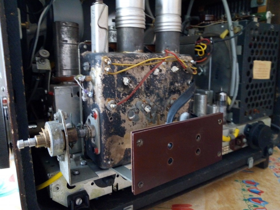
The tuner is mounted next to the VHF tuner using a bracket. It seems no tuning indicator wires are attached. [ibid]
|
The cover of the UHF, which stuck outside the regular backplane, was made of cardboard and not very solid. [ibid]
|
|
After these first almost opportunistic retrofit solutions, a much more structural set-upgrade effort was launched, with retrofit UHF solutions all TV sets from 1958 and later (so starting with the TX250 family up to and including the TX310 family). Such a retrofit set received a similar family name as a tuner (effectively AT6327 to AT6350), but contained considerably more than just the tuner module: mounting brackets, antenna connectors, an additional tuning knob, a channel indicator and all electronic interconnect components. Although I haven't been able to confirm it, I assume that the tuner module that formed the basis of the upgrade sets was the A3 263 77, the standard tuner by then. Installation required a complete de-mantling of the TV set and must have been a time consuming affair. But then, to be fair, when properly executed the upgraded sets looked professionally, as if the UHF was built-in from the factory. E.g. the UHF tuning was often implemented as a third knob on the same axis as the VHF drum tuner and fine control, while the tuning indicators were inserted in the TV front panel. To give an impression of the complexity of these upgrades I have included two examples below, but also because I love these style of drawings.
|
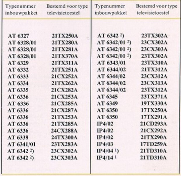
Overview of the many different UHF retrofit service packages for the different Philips TV sets. [Philips Television Product Catalogue 1962-63, via Oudio.nl]
|
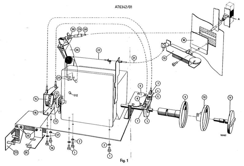
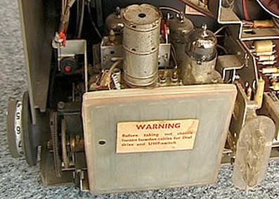
The installation drawing for the AT6342 UHF retrofit package for the 21TX300 tuner family. Knob 9 is the third knob on the VHF tuner control axis (11 is the VHF drum rotator, 10 the VHF fine tuning). Wheel 3 is driven by knob 9, operating two string-tightened wires from construction 4-8 to wheel 14 in construction 12-15, which rotates the UHF tuner axis. From this axis a second set of string-tightened wires 21-22 operate the front panel tuning indicator 19. The front panel VHF-UHF switch A operates the Bowden cable 28 towards the new VHF-UHF switch 26 that was mounted on top of the VHF tuner. [Philips AT6342 installation instruction]
|
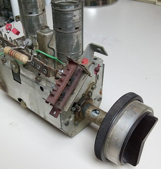
Example of a retrofitted VHF-UHF switch on an old AT7634/80 (A3 792 98) tuner. These are the elements 26-30 in the drawing left.
|
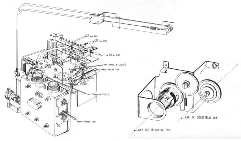
Installation instruction for the French FD 35 078 UHF tuner in the CF2318 luxury TV set. The concept is very similar to the AT6324 above, although the UHF tuning axis rotation is now accomplished through wheels instead of wires, see the right drawing. What is interesting here, assuming the beautiful drawing is correct, is that the UHF tuner is of the very first generation, with left-sided RF input and all alignment points on the back. In which case it can not have been the FD 35 078, since that was a different tuner. So I suspect the factory code of this module is incorrect. [Philips CF2318 upgrade instructions via TSF-Radio Forum]
Example of a UHF-prepared but not yet equipped TV. This is the 23TX315A from 1962. Below the AT7635 VHF tuner an empty slot is ready for mounting a UHF tuner, the wires for the electrical connections are also ready, as is the antenna connector. Note that the VHF tuner is not yet equipped with a VHF-UHF switch!
|
Example of a TV with UHF retrofitted, here the 23TX350A. We can see the three channel selection knobs on the same axis, with the dark UHF outer knob added. The wires and wheel of the VHF-UHF switch are also nicely visible. [Marcels TV Museum]
|
Tuner basics 8 - Image rejection
With the RF channels moving into the UHF band in combination with a much higher number of channels, another fundamental RF reception phenomenon became important: image rejection. During the down-conversion process the wanted signal and local oscillator signal are mixed, resulting in the difference frequency at the Intermediate Frequency (IF). However, the IF is the absolute value of the frequency difference because in real life we can not distinguish between positive and negative frequencies. A consequence of this is that a signal at the same frequency distance from the LO opposite the wanted signal will result in the same IF. This is the "image signal". For the TV channels in VHF-I and III bands the image channels were outside the TV band and proper frequency planning avoided finding strong signals there that could interfere with the TV reception. See the figure below.
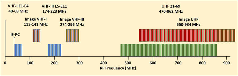
The location along the frequency axis of the image channels of the different TV bands. It clearly shows that for VHF-I and III the image channels are outside the TV transmission band, whereas for UHF the majority of the channels acts as the image for another TV channel.
For TV specifically the image channel issue is a serious challenge, because there is a real chance that the unwanted image signal is (much) stronger than the wanted signal. Without further measures the unwanted image signal would in such a case appear at the wanted IF much stronger than the wanted signal, giving severe interference or worst case loss of reception. In fact one of the reasons that UHF failed initially in the US was due to the bad image rejection of the early receivers, which necessitated keeping (image) channels unused, thus destroying the UHF business case that was based on the availability of many channels.
The solution to the image channel problem is filtering. The tunable Band Pass Filter (BPF) of the tuner needs to be of sufficiently narrow bandwidth to provide good suppression 75-80MHz away where the image channel is located. As we've seen above, the bandwidth of the AT632o UHF tuner was indeed kept at 8-12MHz, only slightly larger than the signal bandwidth. In practice this gave an image rejection of 45dB, given the bandwidth and the state of technology a very decent result. In all this it should be kept in mind that realising a tunable BPF such that its bandwidth and centre frequency are constant over the full (400MHz!) tuning range is one of the main challenges of tuner design.
The solution to the image channel problem is filtering. The tunable Band Pass Filter (BPF) of the tuner needs to be of sufficiently narrow bandwidth to provide good suppression 75-80MHz away where the image channel is located. As we've seen above, the bandwidth of the AT632o UHF tuner was indeed kept at 8-12MHz, only slightly larger than the signal bandwidth. In practice this gave an image rejection of 45dB, given the bandwidth and the state of technology a very decent result. In all this it should be kept in mind that realising a tunable BPF such that its bandwidth and centre frequency are constant over the full (400MHz!) tuning range is one of the main challenges of tuner design.
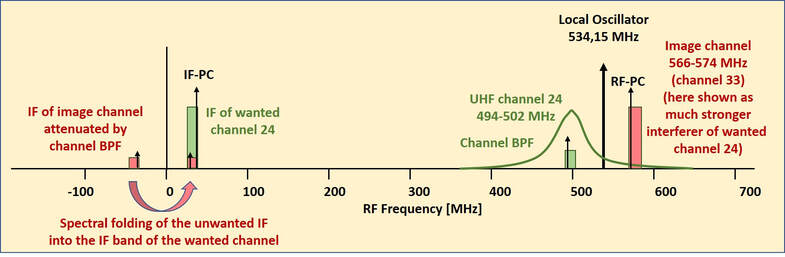
Illustration of the mechanism of image channel interference. Green is the (weak) wanted channel 24, red is the much stronger interferer image channel 33. Both will fold to the IF band between 32 and 40MHz, where especially the image picture carrier will lead to sound distortion. The only means to reduce the interfering image channel is the tunable tuner BPF. It should reduce the image channel to a level of more than 56dB below the wanted picture carrier. Given a fixed IF distance, the only way to achieve this is higher order BPF to guarantee sufficient attenuation at twice the IF distance.
AT6321, the first volume UHF tuner, 1960
|
The first model KR 361 60 did not live long, and was clearly the first product requiring further optimization. So the next year, 1960, the AT6321/01 was released, with optimizations that seem to have been mainly targeted at manufacturability. Firstly, probably driven by practical reasons related to mounting the UHF tuner inside TV sets, the frame was mirrored: looking into the opened tuner the RF input was now on the right side and the axis for the variable capacitors on the left. But more importantly, alignment capacitors were as much as possible moved from the back side to the top, in between the two valves. Only the three alignment capacitors at the bottom of the filter strips still required acces from the backside. This tuner, with factory codes KR 361 77 and 97, was the first to be used structurally in the high end sets like the 21TX290, 21TX300 and 21TX310 from the Eindhoven Apparaten Lab, as well as the 21TD310, 21TD320 and 21TD330 from the new Krefeld factory. This tuner was also sold to third parties under the Valvo brand, which required that like in the VHF tuners also an Automatic Frequency Control version was offered, similar to the KR 361 54. However, in contrast to the latter the new AFC used for the first time a reverse biased BA102 varicap diode, using the (much larger) capacitance variation of the depletion region and providing a larger fine-tuning range.
Finally multiple sub-versions were available, e.g. with full internal dual-tuned IF filter (where normally the second half of the IF filter was external) and versions with a damping resistor over the IF filter, probably to provide wider IF bandwidth e.g. for French 819-line reception. |
Mechanics (top) and circuit diagram (bottom) of the Philips AT6321 UHF tuner. Main difference with the first KR 361 60 is the mirrored housing and alignment moved from the back to the top. The circuit has remained largely identical. [Philips Valvo AT6321 tuner documentation]
|
One of the first platforms that was prepared for and/or equipped with UHF tuners was the TX300 from 1961. Here the Eindhoven-built 23TX330A Automatic. Lower right the UHF tuning dial is visible. [RadioMuseum.org]
|
The Plips TX/TD300 platform introduced a new PCB concept for the small signal functionality, which could swing out sideways for easy access. Lower left in this 23TX330 the VHF and UHF tuners. [RadioMuseum.org]
|
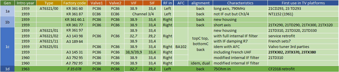
Overview of the first generation Philips UHF tuners AT6321. Factory coding seems to have been fairly messy, because e.g. the KR 361 60 only obtained a .1 suffix despite a complete mechanical change, while the A3 792 95 code was used for two different tuners (the 2nd version had dual trimmer capacitors at the bottom of the tuned filters). Similarly, the entry on the French F 35 078 is based on a drawing, where I suspect the code is wrong since the real F 35 078 was different (see the next generation). The last column shows that use in TV platforms of this generation was still very limited.
Tuner basics 9 - Cross modulation
With the increasing number of received TV channels the linear performance of the receiver became a more important characteristic. Or more specifically, the amount of non-linear behaviour, so the deviation from the ideal linear characteristic of an amplifier. Because the main function of the successive RF and IF bandpass filters is to eliminate the unwanted channels, the non-linear behaviour is most critical at the stage before the first bandpass filtering takes place: the RF input pre-amplifier. In the ideal case this pre-amp will linearly amplify all signals (so multiple channels at multiple carrier frequencies) at is grid. In practice the triode characteristic is not purely linear, showing additional 2nd, 3rd and higher order characteristics too. When multiple channels with different frequencies are applied at the input of a non-linear device (e.g. an amplifier) this will give rise to inter-modulation. This is of course the same mechanism on which frequency mixers are based, only there it is the desired characteristic in order to achieve frequency up- or down-conversion. In amplifiers it is in contrast an unwanted characteristic. But the mechanisms are completely identical: multiplication in the time domain is equivalent (through the Fourrier transform) to subtraction or addition in the frequency domain. In practice it is especially the third order behaviour that causes problems. Second order mixing of two input signals with frequencies f1 and f2 usually results in out-of band signals (either f1+f2 which is much higher or f1-f2 which is close to zero). But the third order mixing of two signals with frequencies f1 and f2 will result in output signals at 2f1-f2 and 2f2-f1 (next to many out-of-band products like 3f1 or 3f2) that can fold back into the wanted signal band.
Broadcast reception (both radio and TV!) with typically many channels at regularly spaced frequencies, is thus sensitive to this phenomena. Because there are many different carriers at the input that will mix there are consequently different inter-modulation mechanisms. a first example is adjacent channel sound demodulation, where third-order mixing results in an inter-modulation signal in the midst of the video signal of the wanted signal, see the picture below. Although the IM-signal will be weak, even a small signal will result in picture Moiré, to which the human eye is very sensitive. It looks as if another image is slowly "walking" through the wanted picture. To avoid any visibility the IM carrier should be 66dB (or a factor 2000 in voltage) below the level of the wanted picture carrier.
Broadcast reception (both radio and TV!) with typically many channels at regularly spaced frequencies, is thus sensitive to this phenomena. Because there are many different carriers at the input that will mix there are consequently different inter-modulation mechanisms. a first example is adjacent channel sound demodulation, where third-order mixing results in an inter-modulation signal in the midst of the video signal of the wanted signal, see the picture below. Although the IM-signal will be weak, even a small signal will result in picture Moiré, to which the human eye is very sensitive. It looks as if another image is slowly "walking" through the wanted picture. To avoid any visibility the IM carrier should be 66dB (or a factor 2000 in voltage) below the level of the wanted picture carrier.
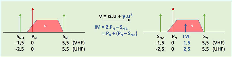
The principle of adjacent channel sound inter-demodulation.
A second mechanism is picture-sound cross-modulation from the adjacent channel, as illustrated below. Although the concepts are illustrated with equally strong signals of both channels, the interference becomes evidently stronger in case the wanted channel is weak and the adjacent interferer (N-1) strong. This is one of the reasons that where possible in the frequency planning of TV transmitters nearby N-1 transmissions are avoided as much as possible. At the same time it should not be forgotten that any two frequencies f1 and f2 where the mixing frequency 2f1-f2 or 2f2-f1 falls within the wanted video band will result in the same Moiré picture distortion.
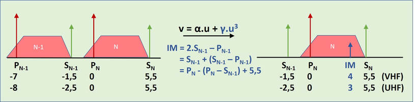
The principle of adjacent channel (N-1) picture-sound cross-modulation.
A third, and more complex manifestation of inter-modulation is cross-modulation. Although there are again multiple mechanisms, we'll focus here on the classical single-carrier cross-modulation. This assumes, within the pass band of the amplifier, another carrier A with a certain amplitude modulation (AM) and modulating frequency fm. In case of a third order non-linear transfer characteristic we now obtain the mixing of fA, fB and fm, resulting in the AM being transferred to the wanted carrier B. The resulting modulation index of the unwanted AM on carrier B is proportional to the non-linear behaviour of the amplifier (gamma/alpha) but also to the power of the unwanted carrier A. A practical specification for cross modulation is that the unwanted modulation is <1% of the original modulation, or at least 46dB down from the picture carrier B. As the formula shows, the only way to limit cross modulation is the reduction of the third order transfer parameter gamma, since all other parameters can not be influenced. Improving the cross modulation performance of the pre-amplifier triodes was thus an important driver for valve development.

The principle of AM cross-modulation.
New VHF frame grid valves, PCC89, PCC189 and PCF86
|
In the previous two generations VHF tuners the PCC88 frame grid dual triode was used since 1956, serving consistently till the end of the decade. By 1959/60 several new frame grid valves for TV receivers were introduced:
The combined introduction of the PCC89/PCC189 in the tuner and the EF183/EF184 in the IF provided a serious overall improvement. On the one hand the much higher transconductance of the valves around 13mA/V provided much more gain per valve, allowing a a reduction of especially the number of IF stages to 2 or 3. Under AGC, with all control valves now variable-mu, cross-modulation was much better, improving multi-channel reception. The only consequence was that the control voltage of the EF183 IF valves had to increase to 12V. The PCC189 AGC was still delayed and limited to -5V, giving a maximum reduction of the PCC189 transconductance to 1mA/V, see the valve characteristics. 
Delayed AGC voltages for TV receivers using the new PCC189 in the tuner and EF183 in the IF. Horizontally the output voltage of the AGC detector, vertically the control voltages for the IF (Ur ZF) and tuner (Ur KW). Note that the tuner AGC still does not increase beyond -5V. [Valvo Kanalwähler, 1961]
The PCF86 was the frame grid successor of the PCF80, another valve that had served for almost eight years, since 1953. Like for the triodes, the frame grid provided an almost doubled gm for the pentode, from 7 to 12mA/V. This in turn yielded better IF-to-RF backward isolation and higher mixer conversion gain (of 4.5mA/V). For all clarity, the triode was essentially still identical to the PCF80 triode, without frame grid! Because the frame grid construction was so much smaller the pentode and triode section of the valve could be placed relatively far apart, for good oscillator isolation. One difference with the PCF80 was the common cathode for the pentode and triode, where the pin freed up was used for a second connection for better grounding.
|

The Vg-Ia and Vg-S characteristics of the PCC189 frame grid valve. Note the logarithmic vertical scale. It shows a graceful degradation of S and thus of the amplification mu=S-Rl. The bottom graph shows the maximum input signal for 1% cross-modulation as a function of S and thus - through the upper graph - Vg. [Philips/Valvo valve information PCC189 through Radiomuseum.org]

Schematic interior view of the PCC89 and PCC189. Note that the "floor plan" is indentical to the PCC88 predecessor, the differences between the valves are in the grid winding. [Mullard Outlook, Vol.12, December 1962 via The Valve Museum]
|


AT7639, the last cascode VHF tuner, 1961
In 1961 yet another family was launched, the AT7639, which would turn out to be the last generation using the cascode input stage. It introduced a number of innovations in several domains:
- PCC89 of PCC189 variable-mu control triodes for the input stage
- Frame grid high transconductance pentode PCF86 for improved mixer performance
- An input for the UHF IF coming from the UHF tuner, with a built-in switch for VHF-UHF band selection
- Re-use of the PCF86 pentode section as IF amplifier for the UHF, including AGC
- New Memomatic, allowing front side step and fine tuning
|
The benefits for point 1. and 2. have been discussed in the previous section. The next electrical innovation was then the introduction of the UHF input. Because of the small parasitics of the PCF86 pentode it could be used as IF amplifier of the UHF IF, which was thus directly connected to the pentode control grid. This in turn required that the VHF input was disconnected, requiring a switch selecting between the two. A second dual-pole switch was used to disconnect the VHF RF supply voltage and instead connect the UHF tuner power supply. The two switches were built into a sheet metal square cover that fitted on top of the tuner module. The switch was operated mechanically, with a Bowden cable coming from the push-button VHF-UHF switch on the TV front panel.
|
The Philips AT7641 VHF tuner, the version without Memomatic. The square box with the VHF-UHF band switch can be seen on the right behind the PCF86 valve schield. [Valvo Kanalwähler, 1961]
|
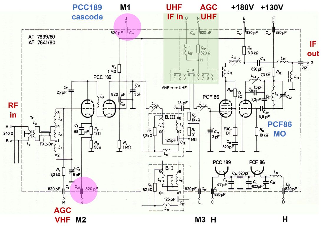
Circuit diagram E1 of the Philips AT7639 and 7641 VHF tuners, introduced 1961. Compared to the previous D4 circuit diagram of the AT7630 changes are minimal and highlighted: two new DC test points M1 and M2 (purple) and the connection for the UHF IF signal (green). [Valvo Kanalwähler, 1961]
|
Although the interior of the tuner essentially didn't change - the switch module was built on top of the tuner module - a number of circuit issues related to the link between the UHF and VHF tuners made things more complex. When switching from VHF to UHF mode a number of settings were changed:
|
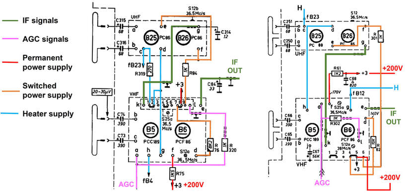
The interconnect between the VHF and UHF tuners. On the left the 23TX371, on the right the TX351A. In the left configuration three switches were used, later model as shown on the right use only two switches. [Philips 23TX351 and 23TX371 service Manuals]
The Philips 23TX371A multi-norm chassis from 1963 for Belgium-French-Swiss border areas was one of the first to use the AT7639 VHF tuner. [Marcels TV Museum]
|
The TX370 chassis still used the 1950s frame construction, with the two tuners mounted high above it on a pedestal. [Marcels TV Museum]
|
In other words, in the opposite situation during VHF operation , the UHF power supply was disconnected, as were the UHF IF output and AGC, while the filament heater currents were partly by-passed through the 270 Ohm resistor. All in all this required three dual-pole switches, one used internally and two externally. From the HA 361 57 model in 1963 this was simplified to only two dual-pole switches by omitting the UHF heater by-passing.
|
The introduction of UHF and the associated VHF-UHF switch increased the mechanical complexity of the TV sets further. Because this switch was deemed to be used regularly by the viewers, it had to be located on the front side, next to the other primary controls. However, the tuners were usually located in the rear of the ever densely filled TV cabinet, for short antenna-to-tuner connections. The VHF-UHF switch was consequently operated using a Bowden cable, in combination with wheels and brackets. They were a regular service nuisance, and form a prominent part of all service manuals. It was thus no surprise that efforts were made to automate this switch operation, eliminating the complex mechanics and wires.
The first solution to be used was a pragmatic one, implemented in the Krefeld TV 23TD362A "Leonardo Luxus AS". Here the Bowden-cable was replaced by a relay box that could be mounted on top of the tuner module and against the switch box. A bi-stable relay now operated the switch arm of the KR 362 78 tuner that contained the dual 2-pole switches. In 1964 the AT7639/90R version was introduced, with the R referring to "Relais", because the relay was integrated into the switch module on top of the tuner. The switch inside the tuner was now reduced to a single dual-pole switch, selecting which input was connected to the PCF86 pentode input. The VHF-UHF switch on the TV front panel, SKc in below picture, selected the power supply for either the VHF or UHF tuners. This further simplified the interconnect between the two tuner modules. |
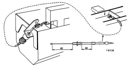
Although it was different for almost every individual TV set, this is a typical construction of the VHF-UHF switch. On the right the front panel push button switch, which is connected via a Bowden-cable and a wheel to the spring-backed switch on top of the tuner house. [Philips 23TX323 Service Manual]
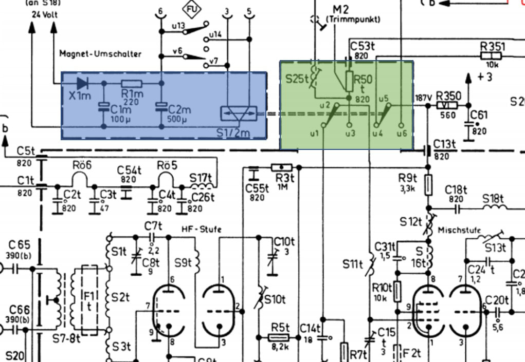
The add-on relay module (blue) that was added to the standard KR 362 78 tuner of the 23TD362 set, with the tuner switch arrangement (green) unchanged. [Philips 23TD362A Service Manual]
|
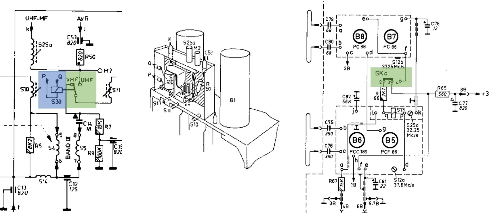
The AT7639R relay-operated VHF tuner. On the left the internal circuit diagram around the relay and band switch; centre the mechanical drawing of the assembly; right the external application. [Philips 23TX400 and A3 293 42 Service Manuals]
The 1963 Philips 23TX400A TV. It was one of the first to use a thin all-plastic cabinet, no longer the wooden frames used so far. [Marcels TV Museum]
|
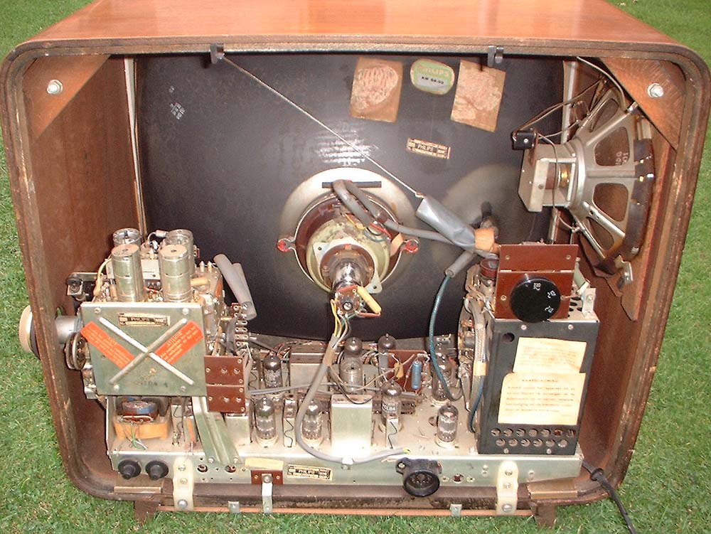
The tuner block of the 23TX400A, the AT7639R on top, with the rectangular relais box clearly visible. Below it the UHF AT6345, the new 860MHz extended range tuner. [Marcels TV Museum]
|
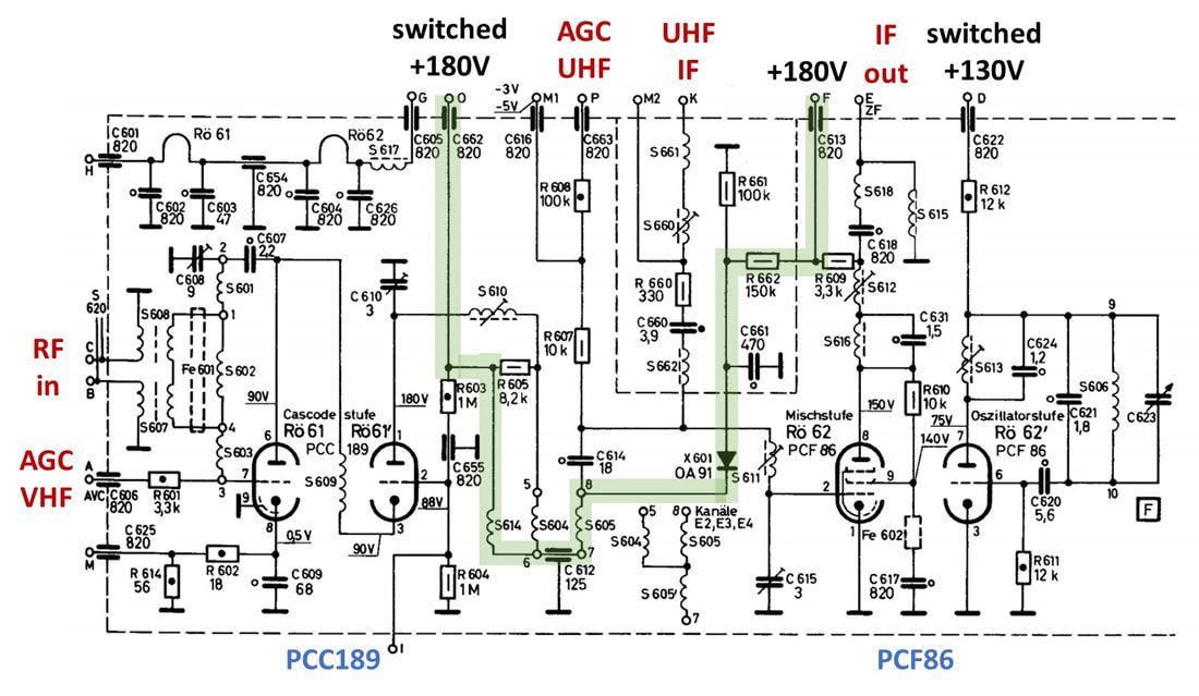
Circuit diagram of the NT1010, NT5701/12 and KR 363 57 electronically switched VHF tuner. [Philips KR 363 57 Service Manual]
|
The third and last improvement for more convenient VHF-UHF switching was the electronic solution. It was first announced in the booklet "Der Fernseh Kanalwähler" (The television channel selector, summarizing state-of-the-art German tuners) as the NT1010 (and NT1009 without Memomatic). It was used as NT5701/12 with factory code KR 363 57 in the 23TD341 Leonardo Luxus.
In this tuner an OA91 diode is the electronic switching element. In VHF mode the diode is in reverse and high-ohmic, with the cathode directly to 180V at point O and the anode due to voltage drop across R662 a few volt lower. In UHF point O is connected to ground, the diode in forward mode and thus a low-ohmic damping resistor of the BPF. |
|
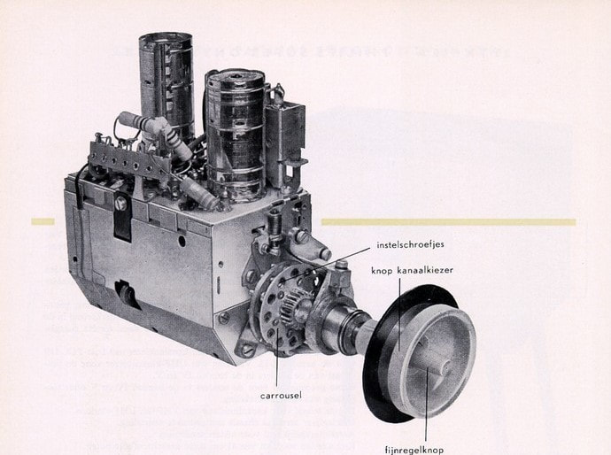
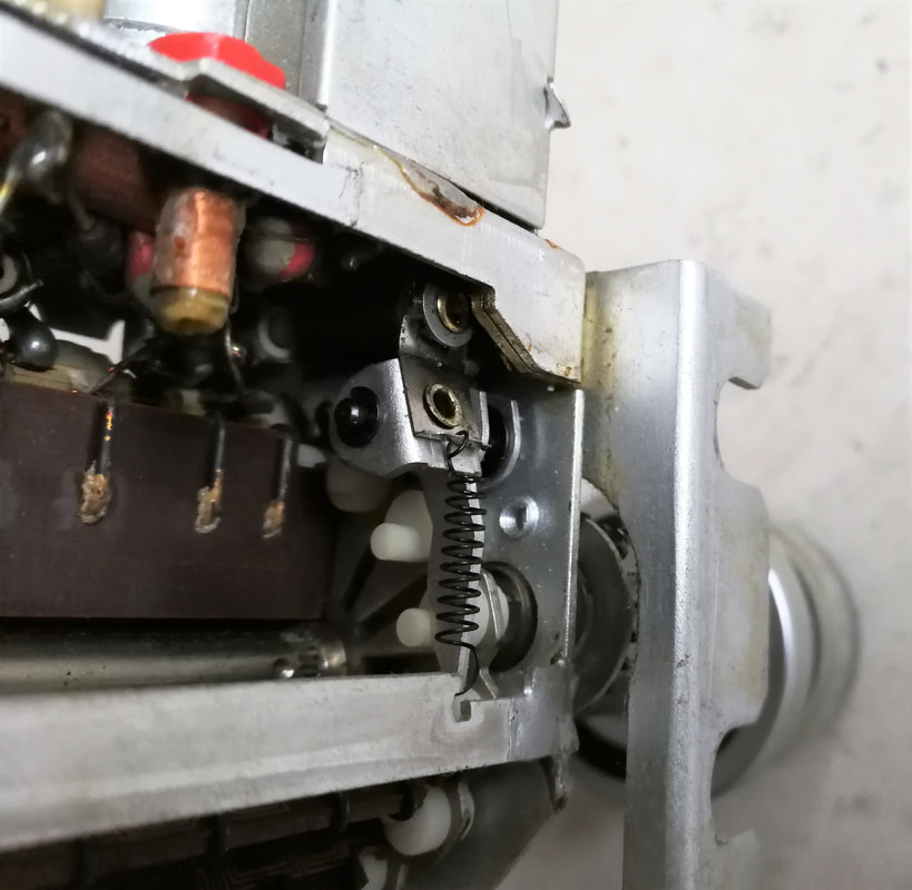
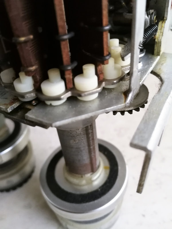
The last innovation in this very successful tuner family was the improved Memomatic. In the first generation Memomatic a complicated mechanical construction was used, essentially guiding the channel selection mechanism to the back of the tuner while the frontal section was used for the channel memory setting. The second generation Memomatic was kept entirely on the frontal side, essentially by displacing the controls off-axis. The carousel with the cantilever mechanism for the tuning capacitor were conceptually unchanged from the 1st generation. The main knob now rotated the drum through a gear construction, visible on the picture, while the fine tuning knob in its centre was aligned with the individual channel screws. The Memomatic had now become a very compact module which, introduced in 1961, would be used for the reminder of the decade on almost all Philips VHF tuners.
|
The AT7639/80 VHF tuner with the new 2nd generation Memomatic channel memory construction. [Philips Televisie 1962-1963 product overview via Oudio.nl]
|
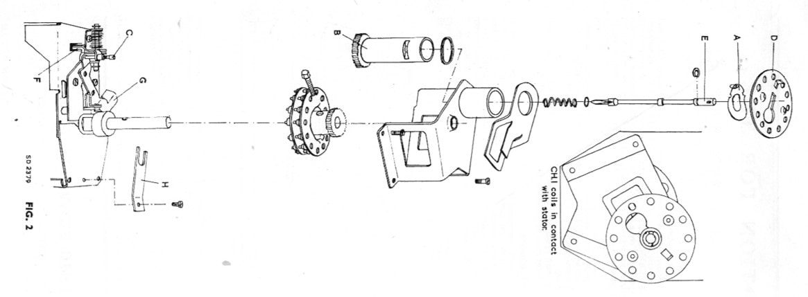
Detailed concept drawing of the new 2nd generation Memomatic (with apologies for the rotated display). The individual channel pre-setting screws in the central wheel will push down lever G, which in turn moves lever F that internally operates the tuning capacitor core. [Mullard HY 143 51 Service Manual through Peter Blackett]
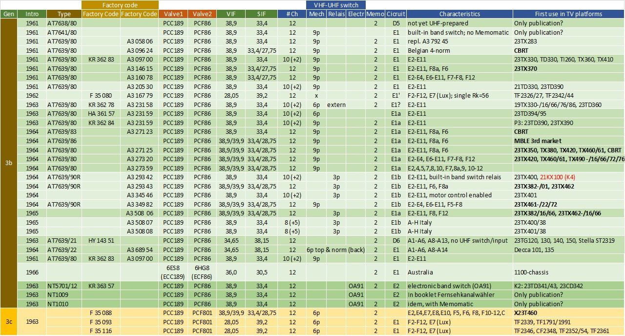
Overview of the Philips AT7639 VHF tuner family. The indication 6p/9p in the column "mechanical switch" refers to the number of contacts. The "2" in the column Memo to the Memomatic generation. Circuit types C4-E1 are explained in the text. TV platforms in bold refer to Belgian multi-norm chassis.
|
Although in publications the AT7638 and 7641 were presented, I haven't found any trace of their actual use, suggesting they were merely potential models. The basis for the majority of the family was clearly the AT7639, which included the successive improvements presented above. As always there are some non-standard models, especially around the switch-over period between valves. The first to introduce a frame grid valve was Mullard, using the remote cut-off variable-mu PCC89. And Australian tuners, both for Kriesler (a company later bought by Philips) and Philips sets, used the American-coded versions of the ECC189 (6ES7) and ECF80 (6BL8). Also French tuners from the Dreux factory only introduced the new PCC189 while keeping the PCF80, as was an NTSC tuner used in Argentinian sets. From 1961 all AT7639's switched to the two new valves PCC189 and PCF86, while Australian sets stayed with 6,3V parallel heater supply and thus the 6ES8 (ECC189) and 6HG8 (ECF86). Finally the French were the first to switch to the PCF801 that will be introduced in the next section.
One interesting development around this time was the active promotion by Philips of its tuners as complete modules for the third party market. An example is the Valvo booklet published in 1961, covering both the previous generation AT7631-37 as well as the latest AT7638-41 VHF tuners, and similarly for UHF. This was most probably driven by opportunity for larger sales, based on the best-in-class of the Philips tuners, as well as the opportunity to provide additional load for the factories and thus better economy-of-scale. Apparently this was successful, and in the coming decade we'll see an increasing use of the Philips tuners by non-Philips companies. Related to these increasing external commercial activities a second commercial family name was introduced: NT1000, NT3000 and NT5000. The latter group name is used most consistently, NT1000 was used for tuners in the booklet "Der Fernseh Kanalwähler" (and it is thus questionable whether these were product codes of real products), while NT3000 was used for Australian tuners. Similarly confusing and still unexplained is the new factory code HA, sometimes but not yet completely replacing the KR Krefeld code. HA suggests a relation to Hamburg, but even Maarten Bakker has not been able to confirm that. With the last AT7639's from 1964/65 the last cascode tuners were produced, after its introduction in 1952 using the ECC81. Since then the PCC84, PCC88 and PCC89/189 had provided an ever improving RF noise and cross-modulation performance. Now, however, it would be replaced by a much improved triode. The last tuner valves; PC88, PC900, PCF801Around 1963 three new RF valves were introduced, that would turn out to be the last valves used in TV tuners. The PC88 was the first, targeted to replace the PC86 as UHF pre-amplifier. Although hardly visible from the outside, this was a quite revolutionary valve design, at least for high volume consumer applications like TV. Within the frame grid concept already used in the PC86, the construction was now made asymmetrical. So far in all triodes the cathode in the centre would radiate in both directions through the grid wound around it towards the anode on both sides of the cathode-grid assembly. See e.g. the PCC189 construction drawing in the earlier section. In the PC88 the cathode-grid-anode chain was limited to one side only, thus reducing the parasitics due to the smaller surfaces. Within the frame grid construction the cathode was moved to one side, with probably only electron emitting material on that side. Because of the reduced emitting surface, to obtain the same high 14mA/V transconductance, the cathode-grid distance was reduced to only 48um. This in turn required that the grid wire diameter was reduced to just 8um, in order to avoid "islands" forming on the cathode. And finally the anode, with the same 9mm2 small active area as the cathode, had to be positioned close to the grid for reduced electron transit times and thus low noise. All this required extreme control and industrial mastership to produce such valves in high volumes! But as a result the PC88 only had parasitic capacitances of 60% of those of the PC86: Cag reduced from 2.0 to 1.2pF (and with external screen from 3.1 to 1.7)! The noise figure at 850MHz was 9dB. Finally, to reduce parasitic inductances (for high resonance and cut-off frequencies) the pinning was changed dramatically. From 2k-3g-2a in the PC86 to k-5g-a , so five grid connections. The PC88 was the first of the last valves, introduced in 1960.

Construction drawings of the PC88 UHF triode. On the left a cross section of the total construction, in the centre a detail of the active region, on the right the pinning showing the five grid connections. [Philips Valvo and Telefunken PC88 valve data sheets through Radiomuseum.org]
A second triode that was developed was the PC900, specifically developed for the VHF pre-amplifier stage. In 1962 the predecessor PC97 was launched, but this valve didn't meet with much success, probably also because it was replaced already the next year by the PC900. Although the PC97 had already some very good parasitic characteristics (Cag of only 480fF) and high transconductance (13mA/V), the PC900 improved this further to 350fF and 14,5mA/V, with an input capacitance Cgk of only 80fF. These values made it possible to replace the cascode stage, which had been the backbone of all VHF tuners, by a single PC900 triode. In contrast to the PC88 the PC900 still had a symmetrical construction, albeit at a smaller scale, fitting in the 7-pin miniature Noval form factor. Additional screens isolated the anode from the frame grid construction.
The third new valve, and the last pentode-triode, was the PCF801, introducing variable-mu characteristics in the pentode for better (UHF) AGC behaviour, while maintaining high direct and mixer conversion gain. Simultaneously the triode also became of frame grid construction. |

In 1961 the German Philips subsidiary Valvo published a booklet promoting their newest AT7638 to 41 VHF tuners as well as the AT6322 and 26 UHF tuners. [Valvo Kanalwähler für Fernseh Empfänger (Valvo channel selectors for television reception), April 1961]

Another interesting booklet presenting the state-of-the-art of tuner development in Germany. Bender worked with Graetz in Altena. It includes the Philips NT1009 and 1010 with electronic VHF-UHF switching. Interestingly, around 1970 Bender joined Philips Elcoma to lead a new tuner development group in Eindhoven. [Der Fernseh Kanalwähler, Heinrich Bender, 1964]

The PC88 [The Valve Museum]

Internal construction of the PC900 VHF triode. The two screens left and right around the grid assembly for shielding it from the anode had a dedicated external pin for grounding. [Valvo Röhren via Radiomuseum.org]
|
Tuner basics 10 - Noise Figure
During the first years of television reception, the absolute performance of the receiver was never a major issue. Although the manufacturers did their best to make good RF receivers (read tuners), people accepted the performance as it was as long as the only/few local channels could be received. With the number of channels increasing and the introduction of UHF this changed. For one thing, it was expected that transmissions of VHF and UHF channels from the same station could both be received. This required that the UHF performance was at least as good as the VHF, a serious challenge at the much higher frequencies. And with the increasing number of transmitter stations, especially across the national borders, people wanted to receive those as well. All this required an increasingly better RF performance, expressed as the Noise Figure of the receiver.
|
In analogue reception, like TV standards covered so far, the picture quality depends upon the Signal-to-Noise ratio, SNR, usually expressed in dB's. If we ignore the influence of Automatic Gain Control (AGC), the noise of a receiver is constant, and determined by the circuits used. The signal strength is determined by the received signal, the distance from the transmitter (the signal strength reduces with the distance^2!), the size and position of the antenna, cable losses etcetera. But ultimately there is a signal at the input of the tuner (Sin) and at the same time noise, which is determined by antenna temperature (To in Kelvins, usually taken as 290K for TV antennas) and the signal bandwidth B as Nin=kToB, with k Boltzmann's constant 1,38 10^-23 J/K.
|
|
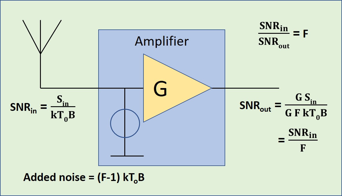
The Noise Factor (F) of an amplifier is now defined as F=SNRin/SNRout and indicates the degradation of the SNR at the output of that amplifier. In other words, in any electronic circuit the SNR can only degrade and never improve, simply because noise is always added. F thus indicates how many times the output is higher compared to the ideal case where no noise was added. In practice the Noise Figure (NF) is used, which is 10 log(F) in dB.
The equivalent input noise, i.e. the output noise divided by the gain of the amplifier, is the noise level at the input required to obtain the same SNR at the input as SNRout: Sin-eq=F kToB. But because the input noise Nin=kToB was already present on the antenna, it means that the amplifier has added a noise equal to (F-1).kToB. Often B is generalized, which means the NF is expressed per unit bandwidth.
When Philips started specifying the noise performance of its tuners it was given as e.g. 8 kTo, which we now know means that F=8 or NF = 9dB. It was only towards the end of the 1960s that NF became the standard noise parameter.
A last consideration regarding the overall NF of a tuner is related to the entire signal chain. Firstly it should be realized that any passive network won't add noise, but at the same time it will have a certain insertion loss L, which should be as low as possible yet won't be zero. A lossy passive network will thus negatively compensate the gain of the preceding stage, while it will degrade the equivalent NF when calculated to its input. In a tuner the the insertion loss of the input match and the inter-stage BPF are thus important. Secondly, using Friis formula, we know that the noise of second and third stages still contribute noise, depending upon the gain of the preceding stages:
F = F1 + (F2 - 1)/G1 + (F3 - 1)/G1G2 + ...
If we apply this to the tuner architecture we obtain the formula shown in the figure below, which expresses the total NF at the input of the tuner before the matching filter. In order to make the pre-amplifier the dominant noise source it requires a large voltage gain Ga, of course the lowest possible noise contribution Fa, while the insertion losses of matching filter and BPF must be as low as possible. In this case the contribution of the mixer, which will be high due to the non-linear frequency conversion and the associated signal reduction, will be reduced maximally.
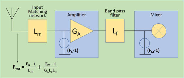
Calculation of the total Noise Factor Ftot of a tuner given the insertion losses Lm and Lf of the matching and band pass filters (both values <1), Ga the amplifier gain and Fa and Fm the Noise Factors of amplifier and mixer, respectively.
AT6322-6352, the last valve UHF tuners, 1960-63
|
The AT6322 UHF tuner with the new PC88 triode was introduced in 1960 in the 23TD320 platform from Krefeld. Changes compared to the previous PC86-equipped AT6321 were minimal, although the connections to the PC88 socket were of course different with its five grid grounding connections. All AT6322's and subsequent versions were of the same mechanical design as the previous family, with 5 chambers separated by screens, right-side RF input, triple tuning capacitors, top-connected filter alignment through capacitors protruding through the top of the aluminium case, while the tubular bottom capacitors of the filters could be aligned either through the back wall or from the front with removed lid. Most variation was in the IF output, which had to do with the type of VHF tuner they connected to. The oldest VHF tuners (before the AT7639) were not prepared for UHF, didn't have the internal VHF-UHF switch nor the second half of the output IF-filter to complement the "half" IF filter in the UHF tuner. In those cases the entire IF output filter was included in the UHF tuner, as can be seen on the circuit diagram (version AT6322/02). Other case required a certain amount of damping of the output, in which case an additional resistor R7 of 2200 Ohm was mounted across the IF output inductor S12a.
|
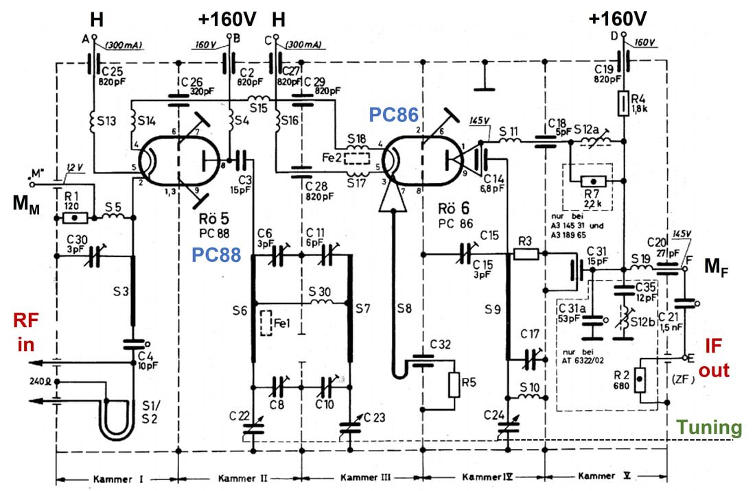
Circuit diagram of the Philips AT6322 UHF tuner and several of its sub-versions. In the A3 145 31 and A3 189 65 the R7 damping resistor was added, in the AT6322/02 the complete IF output filter. Mm and Mf are DC measurement points for checking the valve settings. [Philips 23 TD330 Service Manual]
|
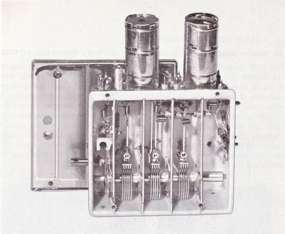
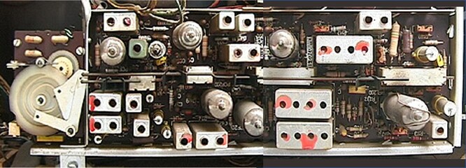
Picture of the Philips AT6322 UHF tuner with removed lid, clearly showing the five chambers and the three tuning variable plate capacitors. [Valvo Kanalwähler, 1961]
|
The Philips AT6326 UHF tuner with Automatic Frequency Control (AFC), using the same concept as the AT6325. I haven't found any trace of actual use of these UHF-AFC tuners. [Valvo Kanalwähler, 1961]
|
|
There was one more step to be made in UHF. So far all UHF tuners had only been capable of covering the 470-790 frequency range, so not the entire TV UHF band up to 860MHz. This became possible with the AT6345, which was launched in 1963. Not many changes were required, only the input matching balun. And almost certainly to provide some high frequency peaking at the high end of the band an additional inductor S21 was connected between the input and ground.
With these optimizations the maximum had been reached with valve-based UHF tuners. From 1963, starting with the Dutch 23TX330, the German 23RD330, the Belgian 23TX350 multi-norm set and the French TF2339, all Philips TV sets would have standard UHF reception implemented. For two years these would all be based on the AT6345 or 6352 tuners, which turned out to be the last valve-based modules. The transistor was around the corner! |
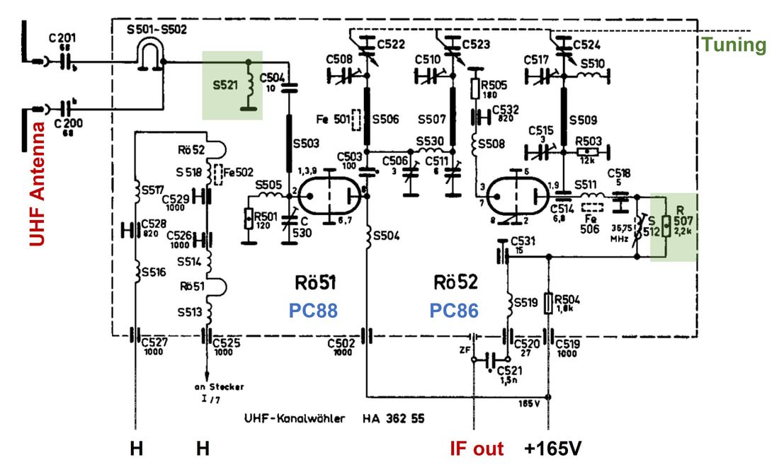
Philips AT6352 860MHz UHF tuner circuit diagram. This specific version has factory code HA362 55, a Krefeld-produced tuner. The additional input matching inductor S21 is highlighted, as is the IF damping resistor R7. [Philips HA 362 55 Service Manual]
|
|
|
|
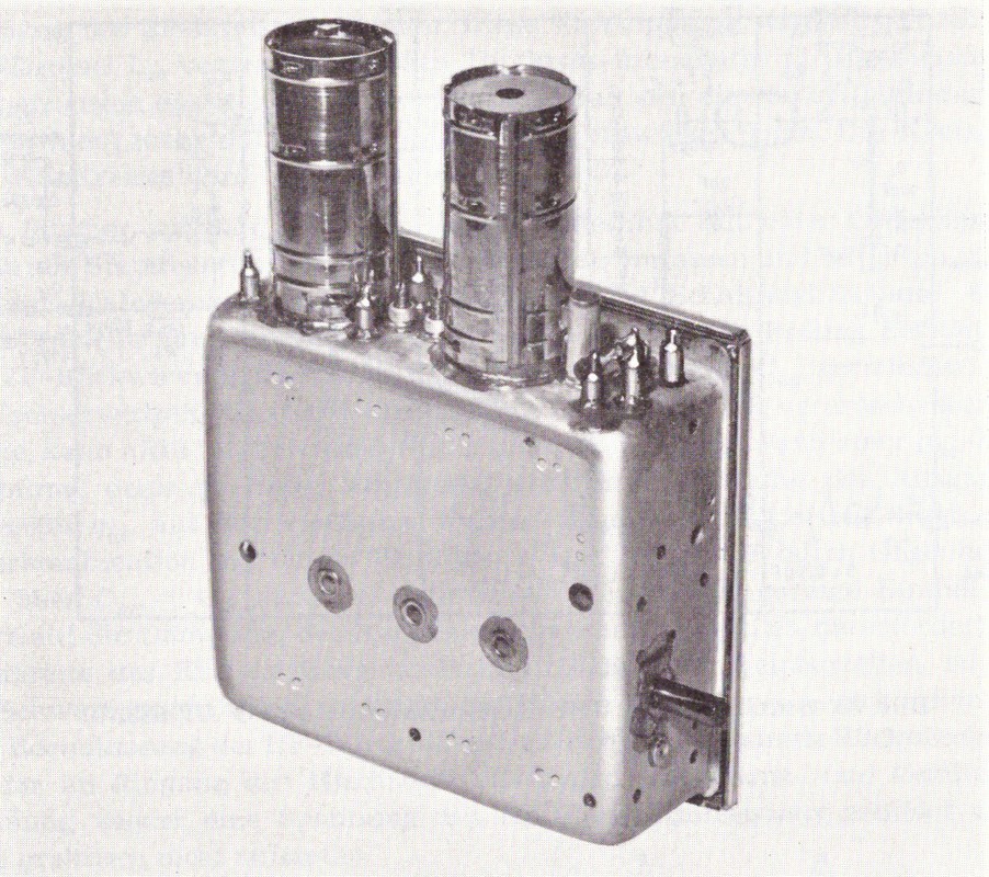
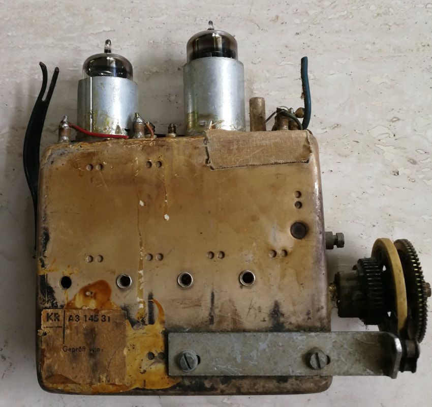
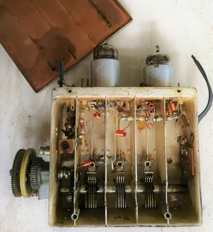
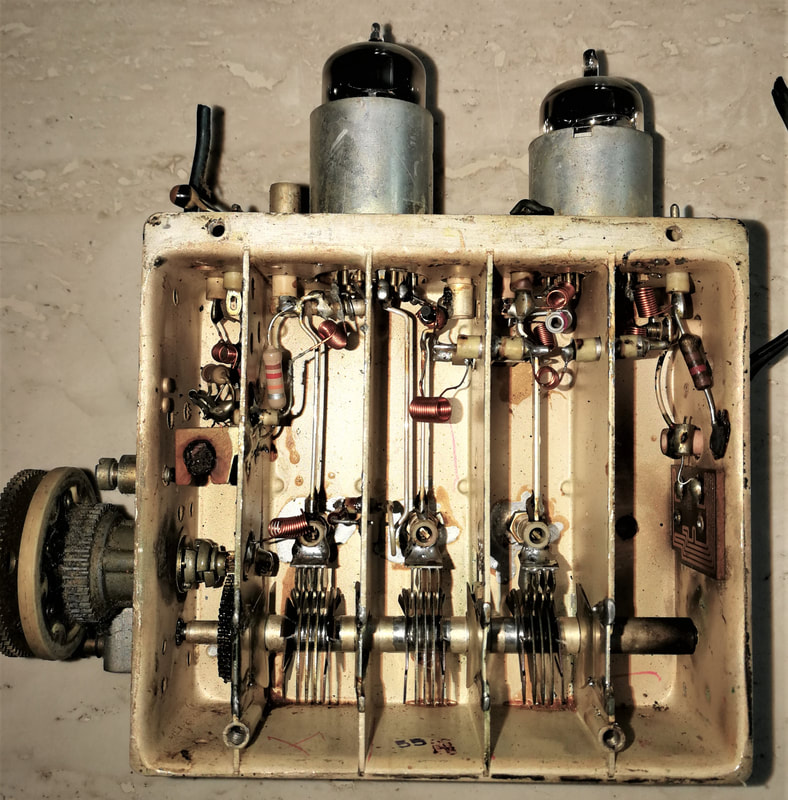
Three pictures of the Philips UHF tuner AT6322 version A3 145 31, produced in Krefeld. The tuning control knob had two gears: for course tuning the central axis only used the internal tuner gear, for fine tuning the external gear could be added. The internal view with removed cover, the inside metal foil of which is visible top left. This tuner still had all components internally. The detailed internal view on the right shows the three tuning blade capacitors, as well as the attached tuning capacitors of the Lecher lines. On the right at the RF input a small PCB with the 300 Ohm balun. [Ite Weide collection]
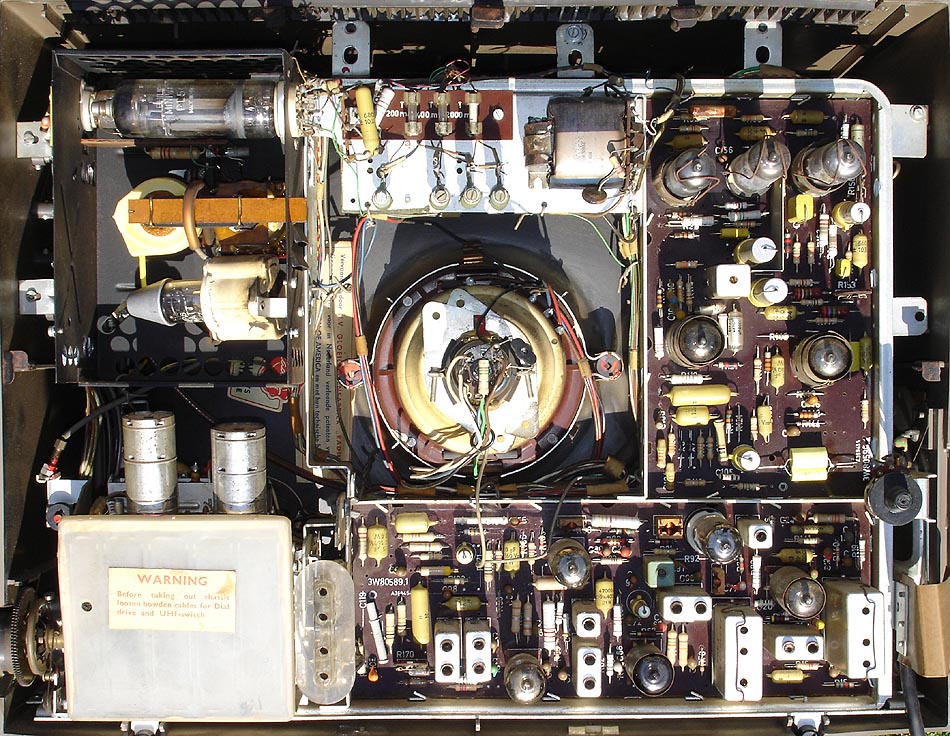
A typical application of the last generation valve UHF tuners, the Philips 19TX410A. Here the interior view. Note how cramped the construction is. [Marcels TV Museum]
|
Close-up of the tuner assembly inside the 19TX410, with in front the AT6345/03 UHF tuner. [Marcels TV Museum]
|
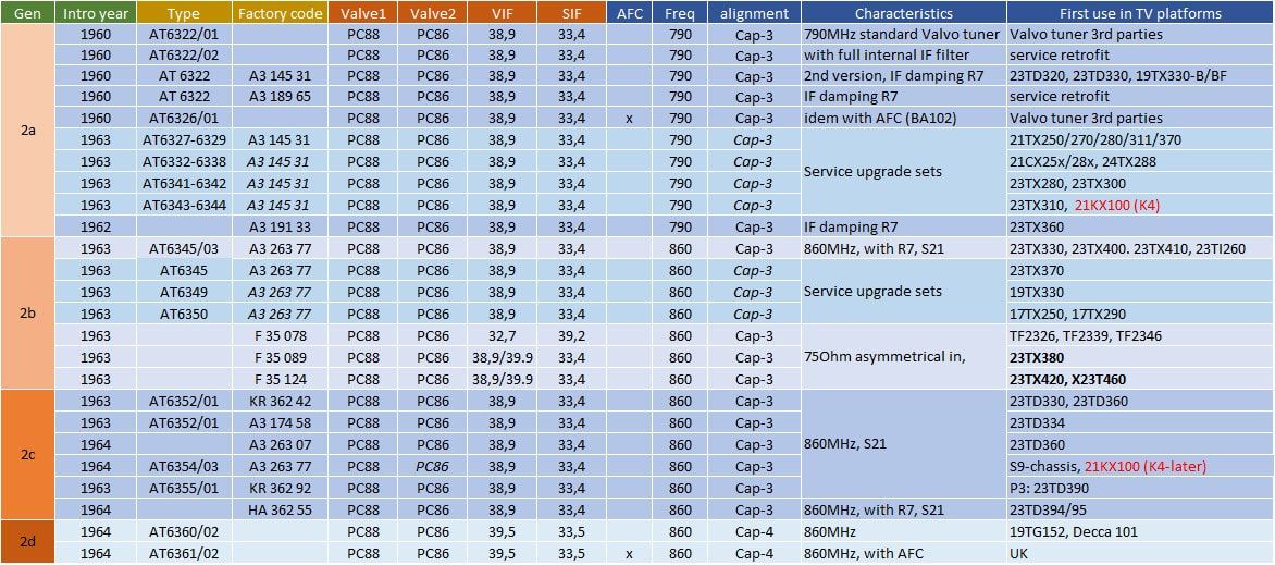
Overview of the Philips family of UHF tuners AT6322 to AT6352, the last valve-based UHF tuners. The light blue section (AT6327-6350) are the service upgrade sets to retrofit UHF tuners to sets missing one. These retrofit sets contained all necessary mechanics next to the tuner module. Speculative data is shown in italics.
Motor controlled tuning
One advantage of the UHF tuners, as compared to the step-wise rotating drum concept of the VHF tuners, was the continuous operation. This allowed for different control mechanisms, including motor controlled tuning. For high end television sets there was always the ambition to reduce the required manual controls and it is therefore no surprise that motor control was considered. The first model to use this was the Krefeld-built 23TD341A Leonardo Luxus (and the console version 23CD342A), since the German TV market for these type of advanced features was much bigger than e.g. the Dutch. It used two standard VHF and UHF tuners with the KR 363 59 motor controlled unit for three UHF pre-set channels. Below drawing will be used to explain the rather complex operation. For simplicity only one of the three channels is shown.
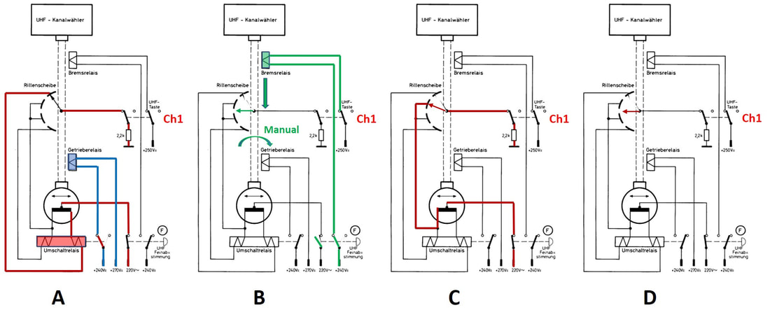
Principle of operation of the KR 363 59 motor controlled UHF tuner unit. Diagram A is during fast tuning, diagram B during channel pre-setting, diagram C during fine tuning and digram D after reaching the pre-set value. In practice the unit was equipped with three channel pre-sets. [Philips KR 363 59 Service Manual]
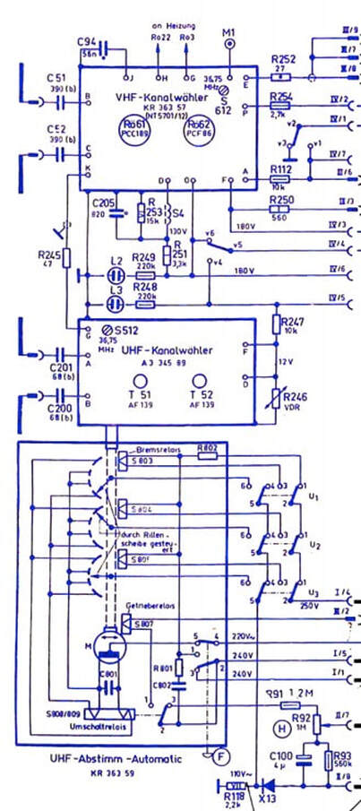
Complete circuit diagram of the Philips 23CD342 tuner assembly, including the motor control module at the bottom. [23CD342 Service Manual]
|
|
|
A similar solution was introduced in the Eindhoven-designed 23TX401A, although with two extensions: UHF had now 4 pre-set channels, while additionally a separate motor control allowed 2 VHF pre-set channels.
As the description and pictures show this was a complex, bulky and therefore without doubt an expensive solution. So apart from the two mentioned luxury sets I haven't been able to find further use of this concept. Interestingly, in parallel, there was another motor controlled application: norm switching in the Belgian multi-norm sets. This was easier, since only a complex rotary switch assembly required activation, and the unit was thus less complex. It was introduced in 1963 in the 23CD352 and 23TX353 and later used in the 23TX382A, 23TX481A and 23TX561A, so essentially one model per generation. Automatic tuning clearly required a cheaper and less complex concept, something essentially not possible with valve-based tuners. 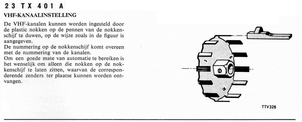
In contrast to the German KR 363 59 that only provided UHF motorized tuning, the Dutch 23TX401 also enabled VHF motorized channel selection. To this end a second motor was driving the VHF main selector axis. By putting two stopping clips on a receptacle wheel on the same axis (see the picture above) the motor would rotate the drum until one of the next stop clip was encountered.
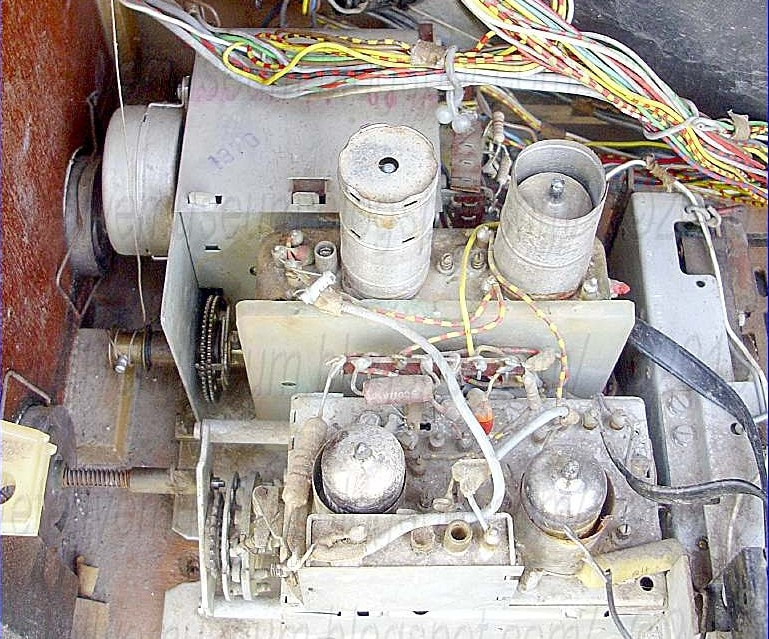
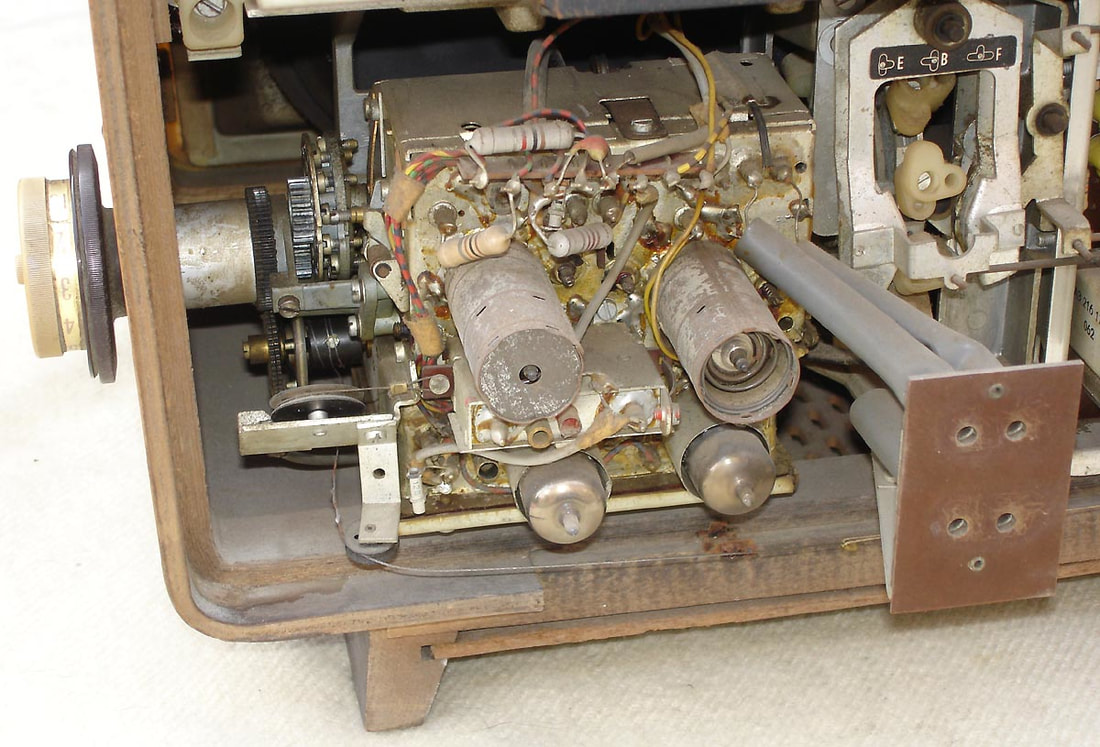
Picture of the entire motor-controlled tuner assembly in a badly aged Philips 23TX401A, with from the back the motor unit, the AT6345 (A3 273 77) UHF tuner and in front the AT7639/90R (A3 293 42) VHF tuner with relay-operated VHF-UHF switch. [Obsolete Telly blog]
|
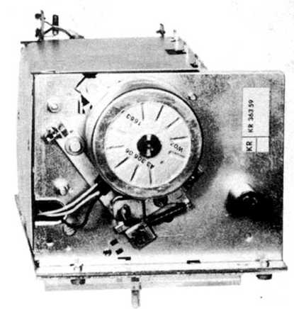
The Philips KR 363 59 motor control unit with three pre-sets for UHF channel selection. [Philips KR 363 59 Service Manual through Radiomuseum.org]
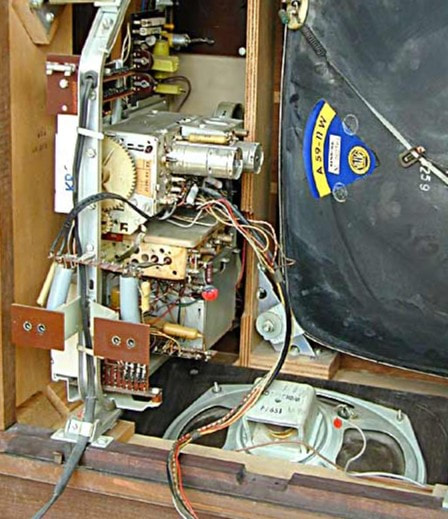
The integral tuner assembly in the Philips 23CD432 television with motor-controlled UHF tuning. Stacked above each other are the VHF, UHF and motor control modules. [RadioMuseum.org]
|
AT7650, the last valve VHF tuner, 1963
|
The PC900 RF triode that was introduced with the AT7650 VHF tuner family substantially simplified the tuner input design, no longer requiring a cascode circuit. Simultaneously the input circuit was modified to become much more asymmetrical as opposed to the pre-dominantly balanced input matching circuits in the previous generations. In fact the tuner housing became rather empty with not more than around twenty discrete components. This is best illustrated using the Krefeld-style circuit diagram of the tuner, with the coloured sections indicating sub-modules.
- the blue balancing transformer was a fairly big component, mounted on the outside of the tuner; - the green filter sub-module was a pre-assembled separate printed circuit board (its main function was blocking filter to prevent IF radiation out of the antenna input); - the yellow sub-module remained outside on top of the tuner main module, although it no longer contained the VHF-UHF switch; - the orange IF output module was in a similar square sub-module on top of the main tuner frame, allowing external alignment of the IF output filter. Compared to the previous generations, the number of alignment points had also reduced to just five capacitors and two inductors, linked to a much simpler BPF construction of just 2 coils. One of the most important alignment points was the neutralisation capacitor C14 (indicated in red) between the PC900 anode and gate. As said, the VHF-UHF switch was deleted from the tuner, since in most sets this was increasingly done with regular switches. Also, because in UHF mode the power supply of the PC900 and the oscillator section were completely switched off. |
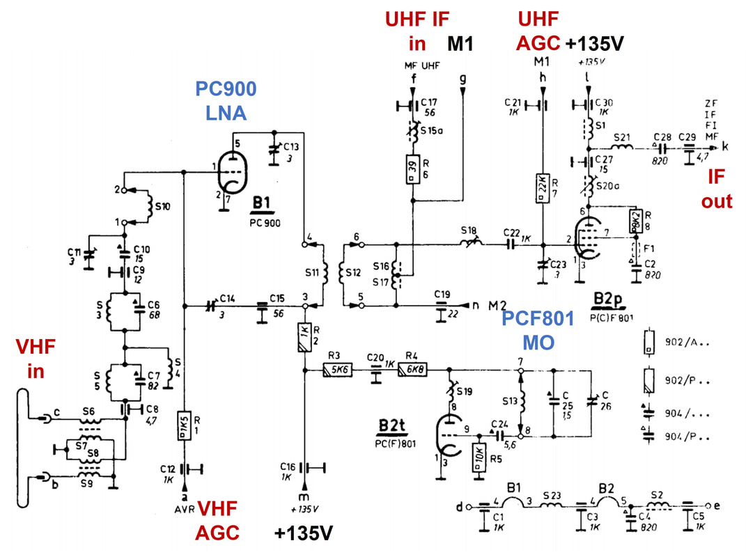
Dutch/Eindhoven style circuit diagram of the Philips AT7650 VHF tuner, factory model A3 668 40. [Philips 3122 108 5005 Service Manual]
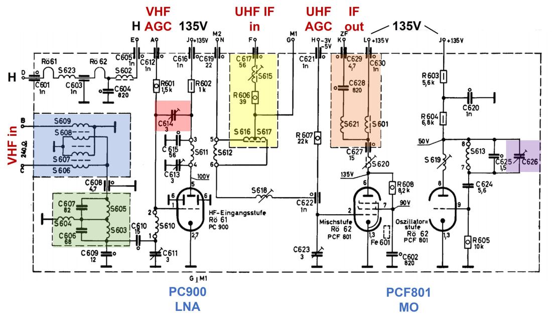
German/Krefeld style circuit diagram of the same Philips AT7650 VHF tuner, with colored sections indicating the different sub-modules. [Philips A3 668 40 Service Manual]
|
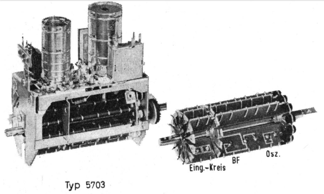
Picture of the AT7650 and NT5703 VHF tuner. On the top side of the tuner we see from left to right the input balun assembly, the PC900 in its metal shield, in the back the IF output sub-module, the PCF801 in its shield and in front right the UHF IF input sub-module. On the drum, which seems to be a 13-position version, we see the printed coils for one channel; from left the input match (Eing.-Kreis), the band filter (BF) and the oscillator (Osz.). [Philips NT5703 Service Documentation, via Radiomuseum.org]
|
The basic tuner of the AT7650 family was known under many names:
- AT7650 followed by a suffix /xx, indicating some sub-version within the family. There were at least 11 sub-versions, mostly related to the different standards and IF's. - NT5703; where it is still not clear when and where NT was used as opposed to AT, but most plausible is the use by third parties. - Product codes dependent upon the fab where it was designed: A3 668 40 from Eindhoven HA 361 59 from Krefeld F 35 139 and 145 from Dreux - V5B; this seems to have been a new style of naming. V referring to VHF, 5 to the generation and B to "Buizen" (valves) - 12nc 3112 xxx factory codes - 12nc 4822 xx service codes The latter two will be introduced a bit lower down. |

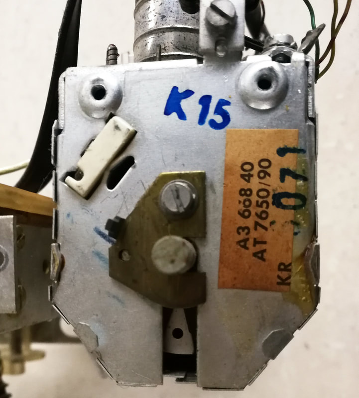


Some close-up pictures of the Philips A3 668 40 VHF tuner in a combined package with the UHF A3 687 70 on the left. -2- Close up of the name shield and marking on the A3 668 40. The lower code KR 6071 refers to some batch identification, KR of course to Krefeld. K15 on the frame refers to week 15, probably in 1964. -3 & 4- The Memomatic tank capacitor fine tuning lever and its small spring to push it against the rotating eccentric cams. -5- Close up of the eccentric cams that are rotated by the fine tuning knob when pushed inwards. Note the relatively small excursion they provide, not more than 3-4mm. -6- The remaining external part of the Memomatic unit; just the outer axis used for the fine tuning and the two 1:1 gear wheels. This total assembly needs to be pushed down (up on the picture) to operate the eccentric cams on the previous pictures. [Pieter Hooijmans collection]
To my surprise I found out that also the mechanics of the AT7650 had changed! The issue is that it is hardly visible from the outside, but only when opening the A3 668 40 in my private collection I discovered it. There are essentially two innovations:
- The number of channel biscuits increased from 12 to 13. This was undoubtedly driven by the multi-norm requirements, where the mix of Belgian, Dutch, Luxembourg and French channels that could be received accumulated to more than 12. The 23TX480/16 and /66 versions of the multi-norm receiver are a nice example, covering channels E2-E12 plus F7 and F8. The impact on the tuner construction was not too big, mainly requiring a drum with 13 regularly spaced slots.
- The Memomatic went internal, and was no longer visible on the outside. It also became much smaller in what I consider a pretty brilliant innovation. In the old Memomatic, see earlier drawings and pictures, there was a multi-step conversion from the adjustment mechanism to the final tank capacitor core movement: the channel fine tuning screw in the Memomatic disk would move a large lever on the outside that transferred the lateral movement to the interior where it was attached to the capacitor core. In the AT7650 this was replaced by a small eccentric cam (the white objects on the pictures), with the eccentric pin moving a small lever up or down. Pressing the fine tuning knob on the exterior of the TV operated the cam rotation through a 1:1 gear. A last interesting aspect is that, like the 2nd generation external Memomatic, the fine tuning cams are not located near the biscuits for which they provide the tuning memory, but in this case 5-slots away. All in all a very neatly engineered construction!
The first platform to use the new AT7650 VHF tuner was the D5, covering the TD400 sets from Krefeld, launched 1965. Note the channel selection and indication: from the bottom 3 UHF preset and selection buttons, the UHF channel indicator, the (small) VHF rotary selector and the VHF channel indicator. This is the 23TD401A. [RadioMuseum.org]
|
The D5 chassis also introduced a new construction concept, with the PCB and other sub-assemblies mounted directly against the swiveling back cover. Not the tuners, they were mounted inside the cabinet to allow the channel indicator displays. [RadioMuseum.org]
|
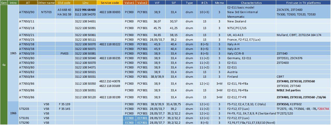
Overview of the Philips AT7650 VHF tuner family. With this generation the new 12nc factory and service codes were introduced. The 12nc in bold indicates an early 12nc style, with the the original A3 code preceded by 3122 99. Quickly afterwards all products complied with the official 12nc coding scheme. The 1966 Australian tuner is included in this list because of its 13-step drum mechanics as well as the timing. However, the valves used are almost two generations older: the 6ES8 is equivalent to the ECC189, the 6HG8 to the ECF86.
As can be seen from the table, the tuner families kept on expanding, covering all regional versions as used by the different Philips factories. However, part of the list are third party models, offered to and increasingly used by the smaller set makers. The majority of the models listed are designed in either Eindhoven (3122) or Krefeld (3112), but we also see the first Mitcham-designed model (3113). Several of these were produced in the Compagnie Belge de Radio et Télévision (CBRT) in Brugge, Belgium, which produced 4- and 5-norm sets for Philips and the sub-brands Siera and Novak, as well as for ACEC in Charleroi . The AT7650 was actively advertised by Philips to other television set manufacturers, where fewer and fewer smaller players could afford and sustain their own tuner development and manufacturing. Apart from the Belgian set makers mentioned above, these were e.g. STC, GEC, Sobell, Rediffusion and Thorn in the UK.
IF and multi-standard in combination with UHF
With the introduction of UHF new IF frequencies appear in the tuner overview tables. As we've seen in the section on the UHF standards there was a clear trend towards more alignment on 625 lines, but the picture-to-sound carrier distance remained much more diversified between 5,5 (most of Western Europe), 6 (UK) and 6,5 (MHz (France and Eastern Europe). In combination with the legacy VHF standards this made multi-norm ever more complex. Below table summarizes the European-centric situation for the standards including the solutions for the IF as applied in the different Philips sets. Most complex was the situation around France. Like in the UK, the VHF and UHF standards in France were fundamentally different, and even a set for only receiving French TV was thus already a multi-standard receiver. In these situations Philips designers always chose to keep the narrow band sound IF frequency constant for both VHF and UHF (at 39,2MHz) with the video picture carrier ending up at 33,7MHz for UHF system L and at 28,05MHz for the VHF system F. When a French set required modification for B/G reception along the French border, the 39,2MHz reference was given up for a separate set of IF frequencies (with like in all B/G receivers picture IF the highest) at 37,7 and 32,2MHz. For Eindhoven-designed sets for the Belgian market, however, a different approach was followed. These were modifications of the standard B/G-sets with IFs of 38,9 and 33,4MHz In the first generations VHF-only 4-norm sets the 38,9MHz video IF was used as reference, resulting in sound IF at 33,4MHz (B/C/F) or 27,75MHz (E). For the new VHF-UHF chassis in contrast the sound IF was used as the reference. This required for the French UHF picture carrier an additional IF of 39,9MHz. While re-using the 39,9 picture carrier for French system-E VHF this then yielded a second sound IF of 28,75MHz. A final multi-standard solution was required for Finland and Austria, both countries next to the border with the Eastern European countries, where there was the desire to receive those system D/K transmissions. These sets were essentially a simplification of the Belgian multi-norm receivers, with a single sound IF (33,4MHz) and 38,9 and 39,9 picture IF.
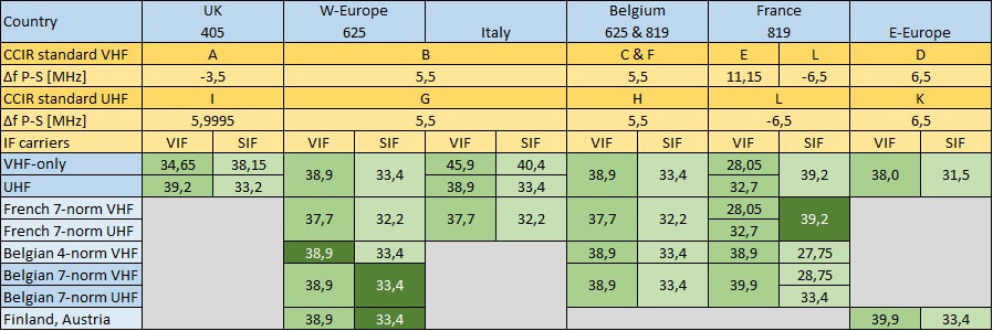
The evolution of the IF frequencies (VIF= Vision IF, SIF= Sound IF) used in Philips TV sets for the different single- and multi-standard televisions. The dark green fields indicate the "design reference" in multi-standard sets.
|
The practical solution for switching between three norms in a multi-norm set became pretty complex, and can be considered to be the ultimate electro-mechanical system solution. It was introduced in the 23TX480, 550 and 560 multi-standard sets from 1963, using as basic tuners the AT7650/86 with 13-channel VHF Memomatic and AT6381 with 4-channel UHF pre-setting. Electrically it built on the solution from the previous 4-norm (VHF-only) generation TX300 from 1961, which had used a first crude form of motor-controlled norm switching. In that chassis the norm-setting per channel was still done with a separate module, connected to the VHF tuner through a Bowden cable. On the AT7650 the suffix /86 meant that a system norm pre-set switch was now mounted on the extended axis at the backside of the VHF tuner. Like the standard Memomatic for the channel pre-setting it provided a similar per-channel system setting, using eccentric notches. These notches could be rotated in three positions: E(urope 625 lines B/G/H), B(elgium 625/819 lines C/F) or F(rance 819/625 lines E/L). Essentially position B selected AM sound, while position F selected AM sound and extended IF bandwidth. When selecting a channel with the rotary drum tuner, on the front side using the Memomatic system the RF fine tuning would be selected, on the backside of the tuner the associated standard setting would be selected. Selection between 625 and 819 lines was done electrically with a BPF tuned to 15.625kHz, followed by a detector that would trigger a relay to switch. The electrical contacts of the E-B-F switch were connected to an electrical motor that rotated a switch assembly to one of the three system positions. Via a gear system a second rotatable disk was activated, which allowed two arms to move in- or outwards, operating thin beams operating the system switches on the PCB. From what I can see a complex mechanical construction of a challenging reliability.
|
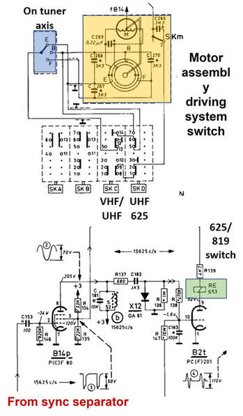
The complex standard selection and system setting mechanisms for multi-norm sets. The upper motor-controlled switching is for the different video bandwidth and sound IF settings, the lower circuit for the line rate switching, This is the circuit in the 23TX561A from 1964.
|
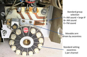
The norm setting assembly on the back axis of the AT7650 tuner. Depending on the excentre setting the arm is moved to either of positions E-B-F. [Oswald Moonen collection]
|
Composite picture of the motor-controlled standard switching mechanism in the 23TX561A. On the left the motor and its attached arms. Attached to these are the thin beams that operate the 4 (rectangular white blocks) switches on the IF panel. [Marcels TV Museum]
|
Fortunately there were also some steps to simplify things further:
- The French System L (625 lines, 6,5MHz picture-sound) was not only used in UHF, but also replaced system E (819 lines, 11,15MHz) in VHF-I while VHF-III system E was gradually discontinued and finally stopped transmissions in 1984.
- The Belgium-Wallonie system C was discontinued in 1977 and replaced by System B.
- The Belgium-Flanders system F was discontinued in 1969 and replaced by system B.
- The UK steadily moved to UHF-only transmission, switching off VHF system A in 1982, Ireland followed in 1985.
AT7660 V3A, a first non-drum VHF tuner, 1965
|
Just before the last valve VHF tuner was produced a final special type appeared, the AT7660, in 1965. This was the first non-drum type VHF tuner since 1953, featuring continuous tuning. This development was undoubtedly driven by the desire to have a VHF tuner with similar tuning behaviour as its UHF counterpart. Over the last years efforts to simplify, automate or store VHF tuning settings had been frustrated by the 2-step VHF tuning procedure: first discrete steps for the drum rotation, followed by continuous fine-tuning with the tank circuit capacitor. The AT7660 solved this through the concept of continuous inductive tuning, as opposed to the continuous capacitive tuning of the very first tuners in 1951. For the first time a VHF tuner was now also much more compact, approaching the form and shape of the UHF versions. In terms of valves this tuner belongs between the AT7639 generation (PCC189 & PCF86) and the AT7650 (PC900 & PCF801), using the same valve combination as the French Dreux tuners F35 093 and 116 from this period, i.e. PCC189 and PCF801.
|
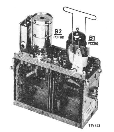
The Philips AT7660 or V3A VHF tuner with continuous inductive tuning. Note the much more compact form factor, as compared to the drum VHF tuners. [Philips A3 640 50 Service Manual via Jac Janssen]
|
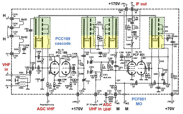
Schematic diagram of the Philips AT7660 VHF tuner with continuous tuning in band III. Green are the band I discrete contacts for channels E2-E4 (note that channel E1 is not populated), the yellow zone indicates the VHF-III variable inductance. [Philips 23TD514A Service Manual via Radiomuseum.org]
The schematic diagram of the V3A shows that it was essentially still a standard cascode input tuner, with the same input match, bandpass filter and tank circuit architecture. Only this time (for VHF-III only!) the channel specific inductors on their respective biscuits were replaced by a continuously variable inductor. These are the yellow sections in the circuit diagram, where a mechanically operated slider modifies the effective length of the inductors S605, S610 (twice) and S620. This allowed continuous tuning from channel 5 to 12. These inductors were executed as printed circuit board tracks on four vertical boards along the orthogonal walls of the tuner module. The channels 2-4 (the green sections), in contrast, were still discrete settings, with discrete inductors for each channel. Channel 1 was not populated (the top contact in the drawing). For proper alignment of the oscillators at each channel the tuner no longer capacitive trimmers, but coils S622-625 needed be opened up or bended for optimal setting, a method that would become standard in tuners later. A final remark as to the circuit is the fact that the UHF IF input signal is galvanically de-coupled from the signal path, and inserted via the transformer S614-15.
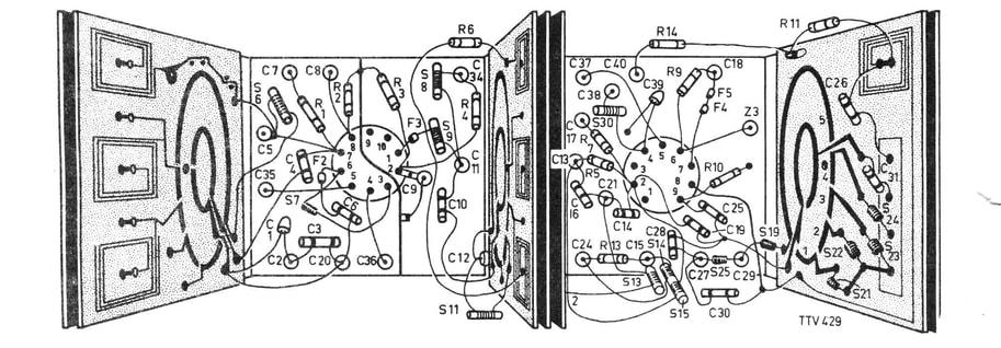
Schematic interior view of the V3a/AT7660 VHF tuner, showing the continuous tuning inductors on the vertical side walls. The chanel 2-4 inductors are partly printed coils (on the left-most wall) and partly discrete (on the right-most wall). [Philips A3 640 50 Service Manual via Jac Janssen]
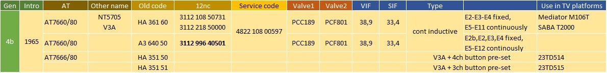
Overview of the Philips AT7660 tuner family, although its difficult to speak of a family given that - as far as known - only a single product was produced. Note the preliminary style 12nc of the A3 640 50.
|
The main purpose of the AT7660 was, however, to facilitate single button channel memory and pre-set. With the old-style two-step approach (first drum stepping, followed by capacitive fine tuning) now replaced by a single continuous rotational/lateral movement. (I still don't have an image of the interior of the AT7660, so it is impossible to say how the continuous inductive tuning was mechanically operated. However, the drawings suggest a linear movement, which means that there must have been some worm wheel-based internal rotation-to-lateral translation). Two sets of push button mechanics were foreseen for the V3A: the HA 351 50 4-button and the HA 351 51 3-button; so far I've found use of the first version.
The mechanical construction was complex, but the main concept was a follows: when a channel button was pressed it would release the others, and allow it to be rotated, performing the tuning action. A slider would move forward or backwards across the threaded screw operated by the button rotation. This slider in turn pushed two rods in conjunction (marked 7, with arrows in the drawing); one forward and one backward. These in turn rotated a first gear (5) that rotated the tuner axis (4). The final fixed position of the slider on the threaded axis thus functioned as the channel setting memory. The diagonal rod on top of the mechanics would move with the active slider and could be used as channel indicator. The V3A plus its pre-set unit were still expensive, intended for high end sets, and effectively only used in two sets from the Krefeld 1965/66 D5F chassis: the 23TD514 and 23TD515. Using the same chassis, the Swiss Philips factory in La Chaux de Fonds produced the M106T and S under the local sub-brand Mediator. But in slightly modified form this concept would emerge as the standard solution in combination with transistor tuners. |
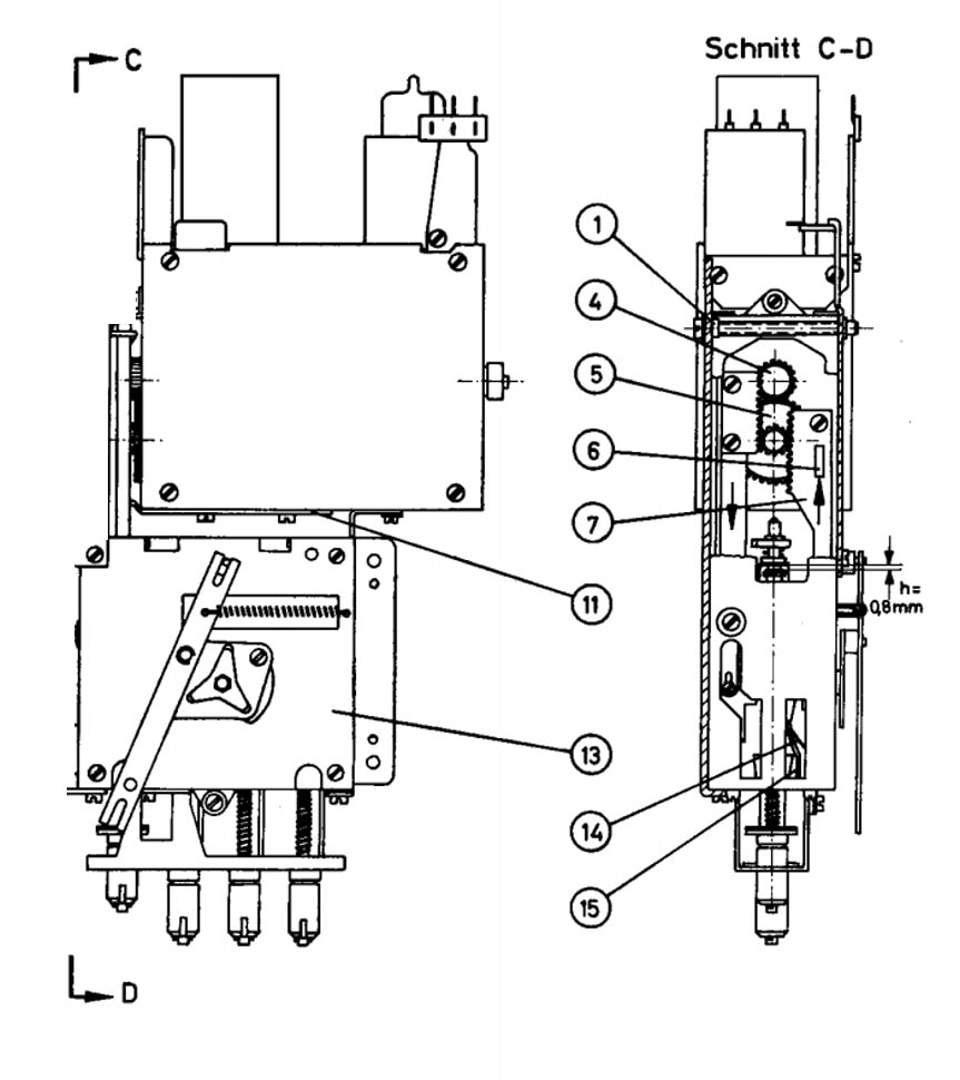
Mechanical drawing of the AT7660 tuner on top (also known as V3A, factory code HA 361 60) and the AT7666 (HA 351 50) 4-button channel memory and pre-set module. [HA 351 50/51 Service Manual via Radiomuseum.org]
|
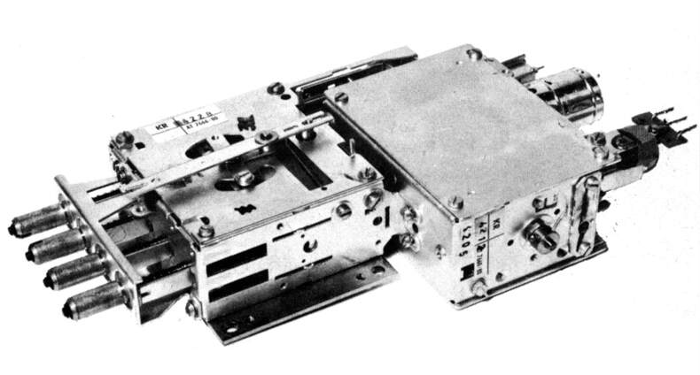
The Philips AT7660-80 (V3A or HA 361 60) VHF tuner on the right, attached to its 4-button mechanical channel setting and memory unit AT7666-80 (HA 351 50). The product codes of both the tuner and the pre-set unit can be read on the labels. [HA 351 50 Service Manual via Radiomuseum.org]
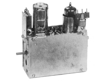
The V3A tuner. In its service manual it has seven different type names or numbers: V3A (the family name), HA 361 60 (German factory code), A3 640 50 (Eindhoven factory code), 3122 996 40501 (provisional 12nc), 3122 108 50731 (final 12nc), 4822 108 00597 (service 12nc), AT 7660 (type name). [Philips HA 361 60 Service Manual]
|
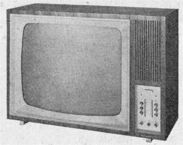
The V3A tuner was - as far as known - used in only two sets: the 23TD514 and the 23TD515. This is the best picture I could find of them. Note the two vertical rows of push button channel pre-set buttons with in between the two channel indicators. [23TD515A Service Manual]
|
Philips 12nc codes
Throughout the 1950s and the early 1960s Philips had been using a system of factory codes, linking every component, however small, to a code number for ordering and traceability. The original basis for this was a central Eindhoven-based system, where most electrical components for TV's and tuners used the A3 category, of the form A3 xxx yy. Codes were assigned in ascending order, where it should be noted that they were used not just for complete tuners, but also for sub-assemblies (e.g. a Memomatic unit) and complete retrofit packages of tuners plus many mechanical components, as we've seen for the AT6340. When more factories started producing tuners we've seen more factory codes appearing:
Probably around 1962 the company had defined a new global coding system, not only covering factory codes but also service components. It used twelve numbers, and is thus known as the 12nc code, a system that was used well into the 1990s. The build-up was a follows (best illustrated using an example):
3112 108 50031 or
aabb ccd efffg
The 12nc turned out to be an extremely valuable and solid system, and is still in use as we speak. The coding system remained consistent from the beginning, the only changes being (sub)-coding centre changes associated with organization changes. For tuners we will thus see the following 12nc structures:
Eindhoven:
The service organizations also used 12-digit codes, which looked similar but bore no relation with the 12nc codes. Any product or component thus received a 12nc (from the production organization) and a service code. The first two numbers of the code (aa) indicated the service organization: aa=48 for consumer service, 53 for professional service, 73 for components service, etcetera. In the service group all products are coded 4822, suggesting central Dutch coding. The tuner category is indicated by the same 108 as above, followed by 118 and 210 later. Tuners were first numbered sequentially in between other service parts in categories 4822 108 and 118. Later on, tuners obtained their own category 4822 210 with sub categories such as 4=VHF and 5=UHF. In service codes 'h' was not a dot-number but part of the regular code. For tuners we see the following codes:
4822 108 00xxx and 4822 118 00xxx
4822 210 4xxxx and 4822 210 5xxxx
The 12nc system roll out was started in 1963, but until 1965 most tuners still received both A3 and 12nc production codes. It is thus fair to say that it took at least 4-5 years to get the 12nc system fully implemented across the entire Philips organisation.
As always the description of this system heavily relies on the inputs from Maarten Bakker, expert on Philips coding systems.
- KR xxx yy and HA xxx yy for Krefeld, Germany where xxx was 361 and later 362 and 363. Although HA suggests Hamburg, the most likely solution was that this was the code of the (new) central coding centre, because production remained in Krefeld.
- MK xxx yy for Mitcham, UK, with xxx = 892 initially. Interestingly unfinished tuners without the valves received codes HY. This is possibly linked to the Whiteleaf factory, close to Croydon, which reportedly manufactured tuner modules but then apparently one assembled the modules, leaving the alignment and testing to Mitcham.
- FK xx yyy for the first tuners produced in Suresnes, France, later FD for Dreux. xx was initially 90, from 1956 onwards the code becomes F 35 yyy, which suggests - like in Germany - the emergence of some central coding authority, with F the generic French indicator. Since around this time (1956) the French Rambouillet factory was opened and dedicated to component manufacturing including tuners, I wouldn't be surprised if the introduction of F 35 yyy coding was linked to production start in Rambouillet.
- PK xxx yy for Monza, Italy.
- ZB A3 xxx yy for Barcelona, Spain. Note that this factory used the different approach by simply putting ZB in front of the A3 code.
Probably around 1962 the company had defined a new global coding system, not only covering factory codes but also service components. It used twelve numbers, and is thus known as the 12nc code, a system that was used well into the 1990s. The build-up was a follows (best illustrated using an example):
3112 108 50031 or
aabb ccd efffg
- aa = HIG code. 31 stands for HIG RGT (radio record player, television), 32 for HIG Licht (Lighting), 33 for HIG Electronenbuizen (Electron Valves), etcetera. Non-released designs could use the sketch code 82; these were not supposed to appear in official documentation and were only for temporary use. Note that the explanation below is only for 31 codes, service codes used a different code build-up. Furthermore, the 12nc referred to the design, and as long as that did not change the 12nc would remain unchanged. So tuners with an Dutch 3122 code (i.e. designed in Eindhoven) could be produced in other factories too. Only when the design was modified locally would the module receive a new localized 12nc.
- bb = coding centre, equivalent to country. The countries were coded alphabetically: 01 Argentina, 02 Australia, 03 Austria, 04 Belgium, 06 Brazil, 08 Denmark, 11 France, 12 Germany, 13 England, 19 Italy, 22 Netherlands, 23 New Zealand, 24 Norway, 28 Portugal, 29 South Africa, 30 Spain, 31 Sweden. Later, with production moving east, e.g. 38 Taiwan and 39 Singapore were added.
- cc = sub-coding centre. In order to harmonize the coding, issuing codes was now done in coding centres. The main coding centre in each country was coded 10, e.g. Hamburg in Germany as in the example, Eindhoven in the Netherlands. Big factories could later become a separate sub-coding centre, like 21 for Krefeld.
- d = category. This ran from simple components to complex modules like a tuner (8).
- e = sub-category. It seems that within category 8 the RF modules were coded as 5. So the combination 'de' for tuners was always 85
- fff = individual product code, type number, in general assigned in ascending order, although some familiy-style clustering might have been used occasionally.
- g = dot number. Usually small modifications not requiring a full new type number release.
The 12nc turned out to be an extremely valuable and solid system, and is still in use as we speak. The coding system remained consistent from the beginning, the only changes being (sub)-coding centre changes associated with organization changes. For tuners we will thus see the following 12nc structures:
Eindhoven:
- 3122 108 yxxxx with y moving from 5 to 6 to 8
- 3122 127 yxxxx
- 3122 128 yxxxx but running in parallel with the previous code
- 3122 237 yxxxx when BU Tuners from 1985
- 3112 108 5xxxx coding centre Hamburg until
- 3112 218 5xxxx coding centre Krefeld TV
- 3112 297 yxxxx Krefeld after becoming BU Tuners
- 3103 128 5xxxx VCR modulators
- 3111 107 yxxxx
- 3111 108 yxxxx
- 3111 237 yxxxx after integration BU Tuners
- 3113 108 yxxxx
- 3139 147 yxxxx Singapore tuners
The service organizations also used 12-digit codes, which looked similar but bore no relation with the 12nc codes. Any product or component thus received a 12nc (from the production organization) and a service code. The first two numbers of the code (aa) indicated the service organization: aa=48 for consumer service, 53 for professional service, 73 for components service, etcetera. In the service group all products are coded 4822, suggesting central Dutch coding. The tuner category is indicated by the same 108 as above, followed by 118 and 210 later. Tuners were first numbered sequentially in between other service parts in categories 4822 108 and 118. Later on, tuners obtained their own category 4822 210 with sub categories such as 4=VHF and 5=UHF. In service codes 'h' was not a dot-number but part of the regular code. For tuners we see the following codes:
4822 108 00xxx and 4822 118 00xxx
4822 210 4xxxx and 4822 210 5xxxx
The 12nc system roll out was started in 1963, but until 1965 most tuners still received both A3 and 12nc production codes. It is thus fair to say that it took at least 4-5 years to get the 12nc system fully implemented across the entire Philips organisation.
As always the description of this system heavily relies on the inputs from Maarten Bakker, expert on Philips coding systems.
Tuner manufacturing
By the early 1960s TV had grown big, both in Europe in general as well as for Philips. And so did the tuner business. Philips had obtained leading positions in almost every (then Western) European country; not necessarily always number 1, but almost always amongst the top3. Because of the bulky nature of TV's transport was very expensive, and TV set manufacturing took place in many countries. In the biggest markets (Germany, France, UK and because of its dominant position also the Netherlands) Philips had big TV factories with nearby picture tube and glass factories: Eindhoven, Krefeld (TV sets) and Aachen (picture tubes) in Germany, Dreux in France, Monza in Italy and Mitcham in the UK. In almost all other countries Philips had local TV assembly based on imported components: Norway, Sweden, Denmark, Finland, Belgium, Austria, Switzerland, Spain and Portugal. And the same happened for tuner modules. So each of the countries with bigger TV factories had its own tuner production department, with various levels of local engineering and development. Although the fundamental concepts seem to have come from Eindhoven throughout the entire period covered so far, we can see varying degrees of local development.
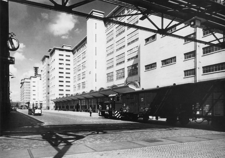
The main road through the Eindhoven Strijp-S complex, with on the right building SL (containing TV and Tuner development), then SK (with Tuner production on the ground floor and TV production above), followed by SAN, SBP and in the far distance the logistics centre ("Veemgebouw") SDM. [Eindhoven in Beeld]
|
In Eindhoven TV and tuner development as well as production were located on the Strijp S complex, in buildings SL and SK. These were very robust multi-story concrete buildings, that survived RAF bombing during the war. Surprisingly, tuner production was on the ground floor of building SK (SKp) while TV production was on the higher floors of SK. Tuner development was on the third floor of SL (SL3) and TV development on SL2.
Krefeld had its own tuner engineering and later development, almost certainly driven by the need for advanced features in the (at least for Philips) mostly mid to high end German TV market. French tuner development is more uncertain, but the most probable scenario is that it started in Suresnes where end 1940s all La Radiotechnique (the French Philips subsidiary) consumer electronics development and production took place. In 1953 TV and almost certainly also tuner production moved from Suresnes to Rambouillet. TV production moved from there to the big new factory in Dreux, near the picture tube fab, in 1957. But radio and tuner production remained in Rambouillet. Tuner development, however, seems to have stayed in Suresnes. |
In the UK we see a similar situation. Initially TV and tuner development and production were in the Mullard Lab and factory in Mitcham, South of London. However, due to the same TV sales growth as seen in France, Mitcham became to small and a major new TV factory was erected at Croydon, Surrey, leaving tuner production in Mitcham. Only later Tuner production would move to dedicated production locations. The first was probably Whyteleafe, which was closer to Croydon, where early 1960s the turret tuners were produced.
All other known tuner manufacturing locations, Monza and Brugge, later also Barcelona, were invariably located in or near a TV factory.
All other known tuner manufacturing locations, Monza and Brugge, later also Barcelona, were invariably located in or near a TV factory.
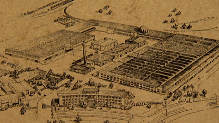
Impression of the large Philips television factory in Krefeld, Germany. The large buildings on the right are the original TV production facilities, Halle 1 to 3. Only towards 1970 Halle 4 and 5 on the left were built, where tuner development and production would be located.
|
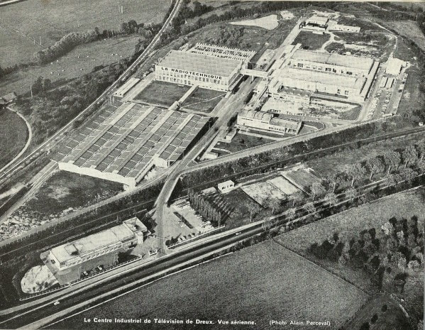
The Philips television factory in Dreux, France, around 1960. Tuners were briefly produced in Suresenes, moving to Rambouillet around 1956, an from there to Nogent-le-Rotrou.
|
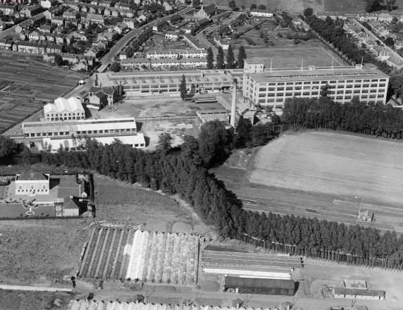
The Philips/Mullard labs in Mitcham, south London, home of television development and tuner manufacturing. [Mullard blog]
|
The full series of 30 pictures has been reduced to below samples. The full series can be found in the book.
|
|
Pictures 21 and 22 show the mounting of the channel biscuits into the drum slots. At this stage the tuner modules received their factory code sticker because they became specific tuners, depending upon the biscuits inserted. We can see this is an A3 271 23. Note the temporary knob for rotating the drum during placement.
In picture 23 we can see the biscuit with its printed coils in the hand of the operator. Picture 24 shows visual inspection of a fully populated tuner module. |
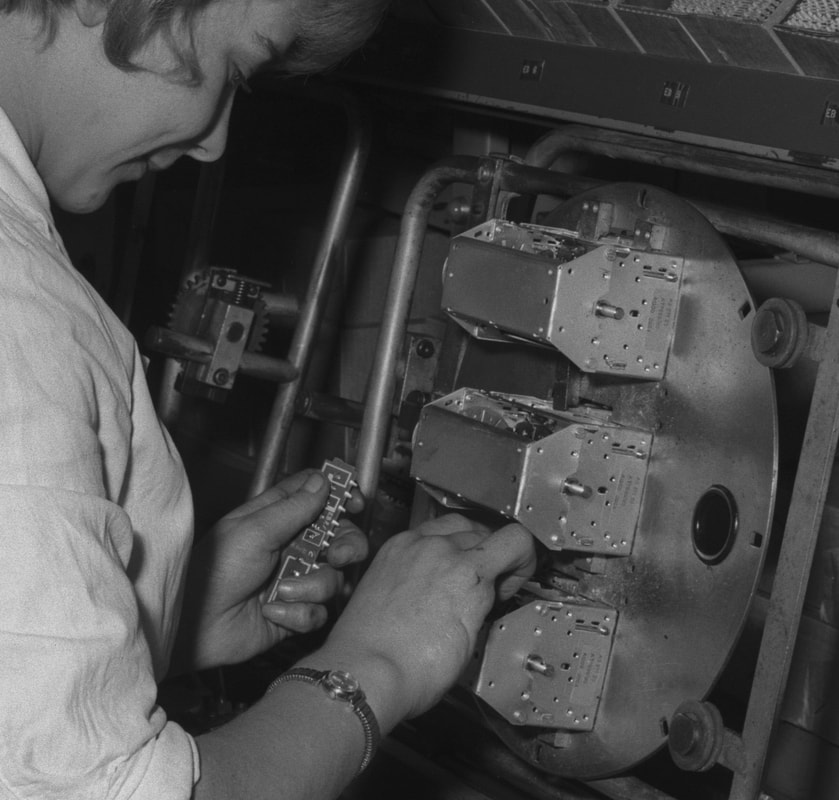
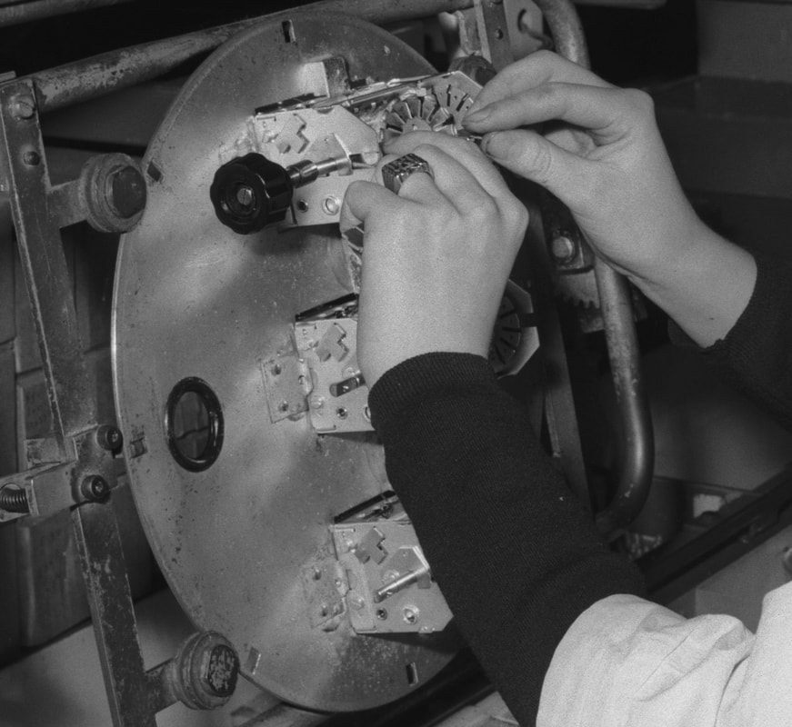
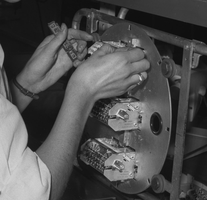
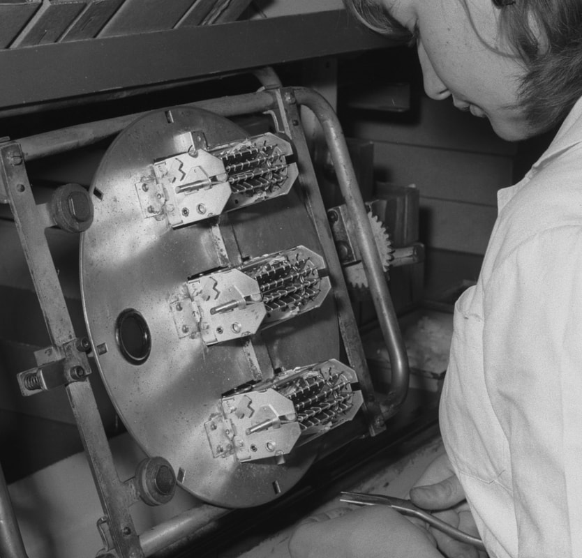
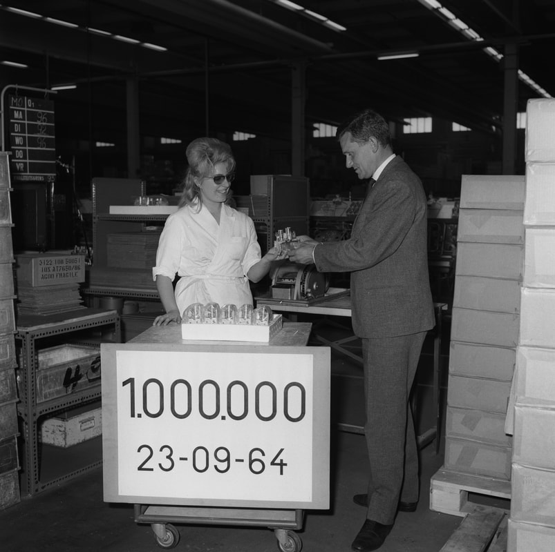
The official hand-over of the 1 millionth tuner produced in Brugge, September 23, 1964, to plant manager F. DeClerck.
|
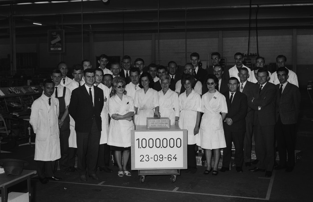
Part of the employees of tuner production at CBRT in Brugge, behind the 1 millionth tuner. The box on which it is displayed says "3122 108 50051 - 10x AT7650/86".
|
Summary
We have reached 1963, and covered some 16 years in pt1 and 2 of the tuner history. The Philips valve VHF tuner had become a fully out-engineered module, with a performance level close to the maximum that could be reached with valves. This was achieved with the quite advanced asymmetric UHF frame grid triode PC900 as RF pre-amplifier, replacing the cascode input stage that had been used for almost ten years. Similar triodes, the PC86 and PC88, provided very acceptable UHF performance across the entire 470-860 MHz band, where it should not be forgotten that 860MHz was at the time a very high frequency for mass-produced consumer applications! In the 15 years of the valve tuner development there had been regular steps in VHF performance through the introduction of new valves, both for the RF pre-amplifier and the mixer-oscillator:
The actual succession of the tuner generation is summarized in below picture, showing the main European markets Germany/ Netherlands/Belgium, France and the UK. Since same colours indicate the same generation, it's clear that especially the older VHF tuner generations lived as long as seven years, a remarkably long time in consumer applications, even in the 1950s. In contrast the first UHF tuner generations had a much shorter life, on average two years. Also visible is the much later introduction of UHF in France and the UK. It seems that in both Germany and the Netherlands older generations continued to be used in e.g. cheaper sets or in sets destined for other, non-European countries. In France, in contrast, the available data suggests that the switch from one generation to the next was more abrupt and across the entire set spectrum. Nevertheless, apart from transition periods, in most countries the normal situation was that all TV's used one standard VHF tuner and one standard UHF tuner. As we will see in the next chapter, that relative application tranquillity changed with the introduction of the transistor.
- RF: EF50 - UF42 - EF80 - ECC81 - PCC84 - PCC88 - PCC189 - PC900
- MO: ECH35 - UF41 - EF80 - ECC81 - PCC84 - PCF80 - PCF86 - PCF801
The actual succession of the tuner generation is summarized in below picture, showing the main European markets Germany/ Netherlands/Belgium, France and the UK. Since same colours indicate the same generation, it's clear that especially the older VHF tuner generations lived as long as seven years, a remarkably long time in consumer applications, even in the 1950s. In contrast the first UHF tuner generations had a much shorter life, on average two years. Also visible is the much later introduction of UHF in France and the UK. It seems that in both Germany and the Netherlands older generations continued to be used in e.g. cheaper sets or in sets destined for other, non-European countries. In France, in contrast, the available data suggests that the switch from one generation to the next was more abrupt and across the entire set spectrum. Nevertheless, apart from transition periods, in most countries the normal situation was that all TV's used one standard VHF tuner and one standard UHF tuner. As we will see in the next chapter, that relative application tranquillity changed with the introduction of the transistor.
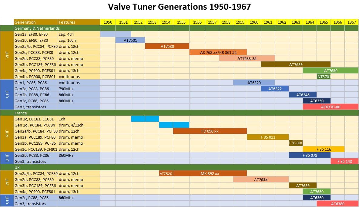
Graphical overview of the different Philips tuner generations between 1950 and 1965, when the last valve VHF tuner was introduced. Identical colours refer to the same platform. The names refer to the ones used in the different chapters in pt1 and pt2 of the Tuner History.
In terms of business the tuners continued to grow in importance for Philips. On the one hand Philips continued to grow as one of the leading players world-wide in television and consumer electronics, with factories being established in an increasing number of countries. Tuner production took place in at least five major factories, with sub-assembly or outsourcing at multiple others, often serving local markets. And finally the tuner modules were increasingly sold to third parties, often the smaller localised set makers that were unable to follow the required economy of scale, and companies that would eventually be taken over by Philips. All in all tuners were becoming a sizeable business.
References pt1 and 2
As long as products are based on valves, like the tuners described so far, finding information is not too difficult. There is a large group of valve afficionados out there, many forums where questions can be asked, and extensive collections of service manuals on line. Below an overview of the main sources used:
- On tuners specifically there are not many books; this is the only one I found:
Der Fernseh Kanalwähler, Heinrich Bender, 1964; contains both a few chapters on RF reception and tuner performance theory, as well as descriptions of contemporary German tuners, including Philips/Valvo. - Valvo Kanalwähler für Fernseh Empfänger (Valvo channel selectors for television reception), April 1961, published by Philips/Valvo Hamburg. Contains a brief introduction on RF and tuner measurements, followed by detailed specifications of the AT7634-38 and AT7638-41 tuner families.
- Philips Electron Tube Division Electronic Application Bulletin volumes 10-16, 1949-1955.
- Philips Electron Tube Division Television Receiving Tubes EF80 ECL80 PL81 PL83 PY80, 1950
- Philips series Electron Valves, volumes I-VIII, published 1940-1953. (I have part I and IV, the others from the web)
- Philips Service Manuals. For these there are multiple sources, so often the same TV documentation can be obtained from multiple sources. Many of them contain documentation on both TV's and tuners. Below a non-exhaustive overview:
- Manuals of the 1756U, 1757U, 2157U, 1458U, 1758U and 1772U UK sets through Jaq Jansen
- Philips Service Documentation Radio-Television-Tape Recorders 1963, 1964, 1965, 1966 and 1967
- www.Radiomuseum.org, especially useful for German sets
- Nederlandse Vereniging voor de Historie van de Radio NVHR
- Frank's Electron Tube Data pocnet, with a very extensive list of sets up to 1965
- DocTSF, especially for French Philips and Radiola sets
- Philips Televisie Service, jaargangen 1-3 (November 1955-October 1958)
- T.V. conversion for I.T.A., C.E. Lotcho, George Newnes Limited, 1957.
- Nederlands Forum over Oude Radios
- UK Vintage Radio Forum , Repair and Restoration
- UK Vintage Electronics Repair site; also contains some Service Manuals
- The Valve Page, no longer active but with a very useful overview of British TV sets by Philips and Mullard.
- Obsolete Technology Telly Museum; contains information of quite some (Italian) Philips sets. Owner can not be contacted but copies from my site without referencing, though.
- Rétro forum, le forum des Radiofil; quite some discussions about Philips sets.
Update history
- November 19, 2017.
pt1 Tuner History page uploaded - December 18, 2017.
pt2 Tuner History page uploaded
Most tables in pt1 extended with new types or new data - February 10, 2018 Update.
Most tuner family tables, and especially those of the AT7650 (VHF) and AT6380 (UHF) substantially extended. The latter based on a Mullard leaflet from 1965 with detailed product specifications (via Synchroton on the UK Vintage Radio Repair Forum), as well as the specifications in the Philips Databook CM-3 1969.
Inserted a dedicated section on the IF values post UHF introduction and completed the cross-modulation Tuner Basics 9 section
Updated the AT7660 section with the HA 351 50 mechanics.
Added table with generation overview.
Added Tuner Basics 10 section on Noise Figure - July 6, 2018 Update
From Ite Weide I obtained the following additional information
- 1958 and 1959 Philips Service sheets on A3 768 xx and AT7632 tuners
- 1960 price list of Philips components including tuners AT7632 and 35;
- 1971 MBLE data leaflet on Philips TV tuners as sold in Belgium: AT7639, 50 and 52T and AT6382, all in /86-versions;
- sample of the AT6322 A3 145 31, pictures added. - September 2018 update
Have added a section on the Radiobuizen-Lab or Dammers-Lab in pt1.
Based on the book by Lotcho which Jac Jansen borrowed me, I extended the analysis on UK IF conversion during the mid 1950s, including more details on the AT7520 tuner.
Furthermore some data sheets received from Jac Jansen, complementing earlier data. - November 2019 update
No major issues. Have changed French production to Rambouillet, based on available information. Similarly have linked UK production code HY to Whiteleafe site. - March 2021 update
I was alerted by a visitor that there was an error in the diagram illustrating the image rejection. The entire diagram has been corrected and updated. - September 2021
Have added illustrative TV set pictures to most sections in Chapters 1 and 2, to better illustrate the applications of the different tuner generations.
Have added a section on the Philips TV organisation and factories.
Have added a section specifically on the Belgian 4-norm sets.
Have extended sections on motor controlled tuning and the AT7650 with more illustrations. All tables updated. - October 2022
Small corrections on the first UHF tuners, which I had labelled - due to lack of formal documentation - as AT6320, given that the first production model was the AT6321/01. However, the AT6320 was the wired remote control unit, so the first tuner model was almost certainly - per the regular Philips naming convention - the AT6321 or when more sub-versions emerged AT 6321/00. - October 2023
Due to the launch of the Philips Television Tuner history volume1, this page has been reduced to the core tuner history.